F9C26-0288BLT 3 LAN Transceiver
Schlumberger Sema
Click to zoom
Application Details
- Equipment Class
- DSS - Part 15 Spread Spectrum Transmitter
- Date of Grant
- Aug 27, 2002
- Application Purpose
- Original Equipment
- Date of Application
- Apr 10, 2002
- Equipment Note
- BLT 3 LAN Transceiver
- Frequency Range
- 911.58000000 - 917.58000000
- Company
- Schlumberger Sema
- Country
- United States
Documents & Files
Document Text
Text extracted from the exhibit documents filed with the FCC. Open a document above to read the original.
Users Manual
Installation Manual, BLT Transceiver 04/11/02 Page 1 of 3 INSTALLATION OF THE BLT TRANSCEIVER MODEL NUMBER: 26-0288 & 26-0166 This device complies with part 15 of the FCC Rules. Operation is subject to the following two conditions: (1) This device may not cause harmful interference, and (2) this device must accept any interference received, including interference that may cause undesired operation. WARNING In order to comply with FCC RF Exposure requirements, this device must be installed in such a way as to ensure that a minimum separation distance of 20 cm is always maintained between the antenna and all persons. Installers and end-users must follow the installation instructions provided in this guide. The module is not modified The module is only used or configured with antennas provided. Do not use other antennas that have not been approved or tested. Doing so will violate the grant of authorization approval and could result in a system exceeding the RF Exposure Requirements or the FCC radiation limits. The module is properly label and if being installed inside a product, were the Module’s FCC ID is not visible, then an external label must be place on the outside of the device, stating the following: “Contains Transmitter Module FCC ID: F9C26-0288” The FCC warning statements and compliance statements found in this installation manual for the module must be replicated in the manual for the host equipment, specifically those related to RF exposure. The module is approved only as a mobile device. The final configuration, where the module will be installed, must meet the 20-cm requirement for it to be classified as mobile. The final configuration must, also, be in compliance with the RF exposure requirements. The module is not approved for portable applications. If portable application is desired, then a separate FCC equipment authorization is required. Installation Manual, BLT Transceiver 04/11/02 Page 2 of 3 The module is installed inside an enclosure that cannot be easily open or accessible to the user, so that the antenna(s) provided cannot be easily change by the user. Typical locations of the system(s) the BLT transceiver is installed in require a “pole-mounting” location. This is usually accomplished by mounting on a street light pole or a utility pole (telephone/electric pole) at 20 to 30 feet above the ground. This type of installation is required for proper RF performance in the network. The BLT LAN Transceiver is built to be mounted in any location, and any orientation providing it is within the ambient temperature range of –40 to +85 degrees C and less than 95% humidity. Connect the RJ45 serial I/O to the host controller using any length cable between 0.5 and 3 meters. The LAN can be powered by any dc power source from 10.5 to 15.5 volts capable of supplying 1 amp with less than 150 millivolts p-p of ripple into the 4-pin Molex input power connector. WARNING: The unit is protected against reverse connection for up to 2 amps for 5 seconds or forward direction up to 3kV for not more than 50 uSec. Exceeding the proceeding may result in damage to the unit. The 12-volt return (ground) connects to pin 4 (top pin closest to RJ45 connector) and the Plus 12 volts connect to pin 3 (top pin closest to the two-pin Molex connector). According to the conditions of the FCC certification, the power cable must have a clamp-on ferrite filter with two turns through it – mounted within 0.1 meter of the LAN power connector. The filter must provide a minimum loss equivalent to Steward ferrite part number 28A2025-0A0. This is a type 28 material clamp-on core having 200 – 300 ohms-per-turn at 100 MHz. The LAN is designed to receive or transmit by switching between two external whip antennae having omnidirectional gains of not more than 3 dBi. Care must be exercised when connecting or disconnecting the OSX right- angle antenna connectors: do not pull on cable; move connectors directly in or out by holding the connector body. Installation Manual, BLT Transceiver 04/11/02 Page 3 of 3 It is recommended that the coaxial connection between the BLT LAN and its antennae be kept as short as practical for the mounting configuration: 0.2 to 0.5 meters. Before application of DC power, check to assure that the cover is secured by the ten screws, that the antennae, SIO, and power connectors are completely engaged, and that the DC source is in the range between 10.5 and 15.5 volts dc. A test program called CELLGRAB.EXE, nicknamed GRABBER, for the host controller is available; versions 3.0-46 or later are applicable. Upon application of DC power, the POWER light should illuminate, followed in 2 to 5 seconds by the CPU OK light. Normal power supply current is 0.2 amps in the receive mode and 0.7 amps in transmit. If, at any time, the CPU OK light goes out, or fails to stay on, the LAN requires either the host controller to issue a BREAK command over the SIO line, or the DC power to be re-initialed. If either of the two indicators remains off, check to assure that DC power is adequate. If the power is o.k., but either of the indicators remains off, then replace, or, return the unit to a repair facility. Warning: Any modifications to the unit, unless expressly approved by Schlumberger, may void the users authority to operate the equipment.
Attestation Statements
Page 1 of 3 Re: FCC ID F9C26-0288 Applicant: Schlumberger Sema Inc Correspondence Reference Number: 23044 731 Confirmation Number: EA727109 RF safety issues 1. OET65: In some cases, the time averaging aspects of the exposure limits may be used by placing appropriate restrictions on occupancy in high field areas. However, such restrictions are often not possible where continuous exposure of the public may occur. In general, time averaging of exposures is usually more practical in controlled situations where occupational exposure is the only issue. If a maximum operating duty factor is clearly defined and specified for the operation of a device, and specific instructions have been given to users allowing them to comply with the exposure limits, this maximum duty factor may be included in the time averaging for demonstrating compliance with respect to MPE or SAR limits for controlled exposure environment. The maximum operating duty factor should ensure that it is unlikely for users to exceed RF exposure limits for normal operation of the device. Users should be instructed and/or warned to avoid operating conditions that may have the potential of exceeding MPE or SAR limits. The maximum operating duty factor does not apply to compliance with respect to MPE or SAR limits for General Population/Uncontrolled exposures where nearby persons typically do not have knowledge or control of their RF exposure conditions. Except for source based time averaging, devices operating in uncontrolled exposure environment should be evaluated for continuous exposure for mobile and portable transmitters. Time averaging does not apply in MPE estimation. Response: Duty cycle removed from formula. MPE now reflects worst-case RF exposure levels. 2. MPE exhibit 2nd column refers to average power. Part 15 uses peak power. Please revise. Response: MPE revised to reflect Peak Power. Page 2 of 3 EMC issues 1) Per the Public Notice on modules, Professional installation cannot be used to satisfy 15.203 for modules. Either use unique connectors (state the type), on all connections or make each permanent with industrial strength epoxy or permanent loctite. Response: Please refer to the uploaded document label “Unique Antenna Statement”. This will explain the mounting mechanism. 2) The device was tested at 5 pulses/second. What is the pulse width? Verify the pulse repetition factor. Response: This sentence is not accurate. It should read "The device was tested at 5 packets/second. Pulse Width= 22.5 mS with OOK modulation, 11 mS with CCSK modulation. PRF = 0.2 (22.5 ms on time + 177.5 ms off time = 200 ms) OOK at 5 packets/second PRF = 0.2 (11 ms on time + 189 ms off time = 200 ms) CCSK at 5 packets/second 3) Processing gain must be shown for each modulation type. For each modulation, provide the data and show the calculations. The BER or Bit error rate of 2.7 X 10^3 seems to high for a data system. Response: this should be a minus 3 (-3), not a ^3, please see below) Please provide a confirmation from the manufacturer that this is the true design specification. Response: The following is taken from our BLT 3 functional specification document: 2.1.3 Sensitivity Receive a CCSK signal level of -114 dBm measured at the antenna port with a symbol error rate of 2.7x10E-3. Receive an OOK signal level of -108 dBm measured at the antenna port with a bit error rate of 10E-3. 4) For each modulation type, provide the theoretical processing gain. Indicate the spread rate/data rate. Indicate the chip/bit rate. Response : The theoretical calculation for the processing gain is as follows: data symbol rate = 19.266 kbaud Spreading code clock rate = 1.22 MHz Processing gain = 10 * log(1.22E6 / 19.266E3) = 18.01dB This calculation is absolutely the same for both OOK and CCSK. Page 3 of 3 Hopefully this answers all of your questions. Please contact me via [email protected] if you require more information. Regards, Juan Martinez Sr. EMC Engineer
Attestation Statements
Compliance of Public Notice 15.203 of BLT 3 LAN Transceiver Editor: David Di Salvo This document is a letter to be part of a FCC compliance documentation to describe compliance with Public Notice 15.203 concerning unique or permanent antenna connections of transmit modules July 3rd, 2002 CDP Deliverable 4.30d ECN Revision History: ECN# Rev. Date Author Page Description ______ 01 Jul 03, 02 D. Di Salvo all 1st Draft Compliance of Public Notice 15.203 CDP Deliverable 4.30d This document is confidential and proprietary to SchlumbergerSema, Inc. 2 Description of Compliance The SchlumberSema BLT 3 transceiver is a sub-component used in two systems. The systems are: Micro Cell Controller (MCC) and Selective Repeater. The antenna used for both systems is an ASPG918 whip antenna, from Antenna Solutions. The antenna is permanently mounted to the MCC or SR enclosure via the antenna’s 7/8 - 15/16 inch hole mount connector with integral N female connection. Inside the MCC and SR, a custom made nominally 12” coaxial cable is used to connect the antenna(s) to the BLT 3 antenna port(s). A type N male connects to the mounted antenna and a type OSX/MCX male connects to the BLT 3 antenna port. Figure 1: Block Diagram of BLT 3 Antenna Connection BLT 3 Transceiver OSX to N Cable Assembly Permanent Antenna Bulkhead Mount X2 with MCC X1 with SR Enclosure
Attestation Statements
Page 1 of 1 Re: FCC ID F9C26-0288 Applicant: Schlumberger Sema, Inc Correspondence Reference Number: 23407 731 Confirmation Number: EA727109 1) Confirm that the only enclosures used will be the MCC and SR enclosures. <-------We confirm that this is the case. In addition the antenna will be permanently attached to these enclosures. How is the antenna made permanent? <-----The antenna is mounted to the MCC or SR enclosure via its integrated threaded bulkhead mount connector which is secured inside the enclosure with a lock washer and nut, tightened with a wrench. The MCC and SR enclosures are pad-locked shut and/or are mounted 20 feet up from ground on a pole. 2) For your information, the device is considered a mobile device not a fixed device with regard to RF safety purposes. Fixed devices are reserved for Cellular base stations or transmitter that are tower mounted or roof mounted. Response: Thanks for the information. Hopefully this answers all of your questions. Please contact me via [email protected] if you require more information. Regards, Juan Martinez Sr. EMC Engineer
Cover Letter(s)
File: R46402 February 28, 2002 Chief, Equipment Authorization Branch, Authorization and Evaluation Division, Office of Engineering and Technology FEDERAL COMMUNICATIONS COMMISSION P.O. Box 358315 Pittsburgh, PA 15251-5315 Gentlemen: The enclosed documents constitute a formal submittal and application for a Grant of Equipment Authorization pursuant to Subpart C of Part 15 of FCC Rules (CFR 47) regarding intentional radiators. Data within this report demonstrates that the equipment tested complies with the FCC limits for intentional radiators. Elliott Laboratories, as duly authorized agent prepared this submittal. A copy of the letter of our appointment as agent is enclosed. If there are any questions or if further information is needed, please contact Elliott Laboratories for assistance. Sincerely, Juan Martinez Sr. EMC Engineer JMM/dmg
Cover Letter(s)
Request for Modular Approval of BLT 3 LAN Transceiver Editor: David Di Salvo This document is a cover letter to be part of a FCC compliance documentation package of the SchlumberSema BLT 3 LAN Transceiver, requesting approval of BLT 3 to be Certified as having met requirements for PART 15 UNLICENSED MODULAR TRANSMITTER APPROVAL (DA 00-1407, Released: June 26, 2000). March 29th, 2002 Part Number 97-xxxx Rev. 01 CDP Deliverable 4.30a ECN Revision History: ECN# Rev. Date Author Page Description ______ 01 Mar 29, 02 D. Di Salvo all 1st Draft 02 Apr 04, 02 all 2 nd Draft FCC Modular Approval Request Doc. P/N: 97-xxx REV: 02 This document is confidential and proprietary to SchlumbergerSema, Inc. 2 Request SchlumberSema requests Modular Transmitter Approval of the BLT 3 Transceiver product line (SLB part numbers: 26-0288 & 26-0166) having addressed the numbered requirements as listed in the FCC document: PART 15 UNLICENCED MODULAR TRANSMITTER APPROVAL (DA 00-1407, Released: June 26, 2000) pages 2 and 3. Numbered Requirements 1. The modular transmitter must have its own RF shielding. The BLT 3 transceiver’s transmitter section is enclosed with its own RF shield and the BLT 3 unit has passed all emissions testing from a FCC authorized test facility. 2. The modular transmitter must have buffered modulation/data inputs. The modulation/data inputs (of the transmit section) are pre-set in firmware. The BLT 3 has been tested at a FCC authorized test facility to verify compliance of the Part 15 requirements. 3. The modular transmitter must have its own power supply regulation. The transmitter section of BLT 3 is power regulated from a DC to DC converter that is integral to the Printed Circuit Board Assembly. 4. The modular transmitter must comply with the antenna requirements of Section 15.203 and 15.204(c). The BLT 3 employs OSX type connectors at its antenna ports. Installations have a cable, OSX to Type ‘N’, with the antenna connected to the Type ‘N’ connector. A whip-type of di-pole antenna is used. The Device will required professional installation. 5. The modular transmitter must be tested in a stand-alone configuration. The BLT 3 was tested as a stand-alone unit at a FCC authorized test facility to verify compliance of the Part 15 requirements. The BLT 3 unit meets the AC line conducted requirements as listed in Section 15.207. Connections to the BLT 3 include DC power and serial input/output lines that are each greater than 10 centimeters in length. FCC Modular Approval Request Doc. P/N: 97-xxx REV: 02 This document is confidential and proprietary to SchlumbergerSema, Inc. 3 6. The modular transmitter must be labeled with its own FCC ID number, and, if the FCC ID is not visible when the module is installed inside another device, then the outside of the device into which the module is installed must also display a label referring to the enclosed module. The BLT 3 unit displays a FCC label attached to the top cover. The installation manual instructs the integrator to place an the following wording on the exterior FCC label of the final product: Contains Transmitter Module FCC ID: F9C26-0288. 7. The modular transmitter must comply with any specific rule or operating requirements applicable to the transmitter and the manufacturer must provide adequate instructions along with the module to explain any such requirements. A copy of these instructions must be included in the application for equipment authorization. The BLT 3 should be installed and operated as per the installation manual. 8. The modular transmitter must comply with any applicable RF exposure requirements. To ensure compliance with FCC RF exposure requirements, the antenna used for this device must be installed to provide a separation distance of at least 20 cm from all persons and must not be co-located or operating in conjunction with any other antenna or radio transmitter. Installers and end-users must follow the installation instructions provided in this user guide.
Cover Letter(s)
April 17, 2002 Federal Communications Commission 7435 Oakland Mills Road Columbia, MD 21046 Subject: AMMEND SCHLUMBERGER FCC ID #F9C260288, EA727109 Gentlemen, The FCC ID # for Schlumberger EA727109 was mistakenly entered as F9C260288. Please amend the ID # to F9C26-0288 as shown in the label diagram. Sincerely, David Guidotti SR. Documentation Specialist
RF Exposure Info
CellNet Data Systems Confidential Last Saved: 05/10/99 5:55 PM Title: Evaluation of ER Exposure from CellNet Transmitters for General Population / Uncontrolled Exposure Methodology: Using Table 1 in Appendix A of FCC OET Bullentin 65 (Edition 97-01), the Maximum Permissible Exposure limit for general population / uncontrolled exposure is specific as a power density: MPE = ƒ / 1500 milliwatts per square centimeter, where ƒ is in MHz (between 300 to 1500 MHz) Averaged over 30 minutes. Based on spherical surface around the source, the minimum distance D can be computed as: D = SQRT (EIRP / 4∏ * MPE) Hardware Average transmit power (dBm) Antenna gain (dBi) Duty cycle (average d over 30 minutes) Avg EIRP (dBm) Avg EIPR (mW) Frequency (MHz) MPE (mW per sq. cm) Minimum distance (cm) Minimum distance (inches) Repeater (Repeat All) 27 5 25% 25.98 396 918 0.6120 7 3 Note 1: The BLT III will be used with an external antenna with a 5dBi gain (Please refer to Antenna Specification (M/N: ASPG918). Note 2: The RF safety exposure statements are mention in the installation guide page 1 of 3. Reference: [1] FCC OET Bulletin 65 (97-01 Edition), “Evaluation Compliance with FCC Guidelines for Human Exposure to Radio Frequency Electromagnetic Fields”, August 1997. RF Hazard Statement The instant device, a Part 15 spread spectrum transmitter, is a fixed device professionally installed inside an enclosed utility meter. Accordingly, the device is not designed to be used by any persion. The antenna associated with the device is not external but is rather also contained within the same utility meter enclosure. The device communicates with a fixed local area network. This transmitter does not fit within the definition of a “mobile device” set forth in section 2.1091(b) of the Commission’s rules, 47 C.F.R. Section 2.1091(b), because it is designed to be used in fixed locations. In addition, the transmitter does not meet the definition of a “portable device” contained in section 2.1093(b), because it is not designed to be used by any person. Furthermore, section 1.1307(b)(1), which is reference by section 15.247(b)(4), categorically excludes this Part 15 device from the requirement to conduct a routine environmental evaluation for RF exposure since the device is neither a millimeter wave device, nor an unlicensed personal communications service device. In any event, based on the maximum output power (+30 dBm) and antenna gain information contained in the underlying equipment authorization application for this device, the emissions for the device are well below the maximum exposure limits set forth in section 1.1310 and 2.1093(d). Furthermore, the device only emits approximately six very brief transmissions in any given one-half hour period, each with a duration approximately 0.0027 seconds. Accordingly, the RF emissions for the device are well within the limits set by the Commission.
RF Exposure Info
CellNet Data Systems Confidential Last Saved: 05/10/99 5:55 PM Title: Evaluation of ER Exposure from CellNet Transmitters for General Population / Uncontrolled Exposure Methodology: Using Table 1 in Appendix A of FCC OET Bullentin 65 (Edition 97-01), the Maximum Permissible Exposure limit for general population / uncontrolled exposure is specific as a power density: MPE = ƒ / 1500 milliwatts per square centimeter, where ƒ is in MHz (between 300 to 1500 MHz) Averaged over 30 minutes. Based on spherical surface around the source, the minimum distance D can be computed as: D = SQRT (EIRP / 4 ∏ * MPE) Hardware Peak transmit power (dBm) Antenna gain (dBi) Duty cycle (average d over 30 minutes) Peak EIRP (dBm) Peak EIPR (mW) Frequen cy (MHz) MPE (mW per sq. cm) Minimum distance (cm) Repeater (Repeat All) 26.7 5 0% 31.7 1479.1 918 0.29426 10.84 Note 1: The BLT III will be used with an external antenna with a 5dBi gain (Please refer to Antenna Specification (M/N: ASPG918). Note 2: The RF safety exposure statements are mention in the installation guide page 1 of 3. Reference: [1] FCC OET Bulletin 65 (97-01 Edition), “Evaluation Compliance with FCC Guidelines for Human Exposure to Radio Frequency Electromagnetic Fields”, August 1997. RF Hazard Statement The instant device, a Part 15 spread spectrum transmitter, is a fixed device professionally installed inside an enclosed utility meter. Accordingly, the device is not designed to be used by any persion. The antenna associated with the device is not external but is rather also contained within the same utility meter enclosure. The device communicates with a fixed local area network. This transmitter does not fit within the definition of a “mobile device” set forth in section 2.1091(b) of the Commission’s rules, 47 C.F.R. Section 2.1091(b), because it is designed to be used in fixed locations. In addition, the transmitter does not meet the definition of a “portable device” contained in section 2.1093(b), because it is not designed to be used by any person. Furthermore, section 1.1307(b)(1), which is reference by section 15.247(b)(4), categorically excludes this Part 15 device from the requirement to conduct a routine environmental evaluation for RF exposure since the device is neither a millimeter wave device, nor an unlicensed personal communications service device. In any event, based on the maximum output power (+30 dBm) and antenna gain information contained in the underlying equipment authorization application for this device, the emissions for the device are well below the maximum exposure limits set forth in section 1.1310 and 2.1093(d). Furthermore, the device only emits approximately six very brief transmissions in any given one-half hour period, each with a duration approximately 0.0027 seconds. Accordingly, the RF emissions for the device are well within the limits set by the Commission.
Test Report
File: R46402 Page 1 of 17 Electromagnetic Emissions Test Report and Application for Grant of Equipment Authorization pursuant to FCC Part 15, Subpart C Specifications for an Intentional Radiator on the Schlumberger - RMS Div. Model: BLT III FCC ID: F9C26-0288 GRANTEE: Schlumberger - RMS Div. 75 Shoreway Rd. San Carlos, CA. 94070 TEST SITE: Elliott Laboratories, Inc. 684 W. Maude Avenue Sunnyvale, CA 94086 REPORT DATE: February 28, 2002 FINAL TEST DATE: February 25, 2002 AUTHORIZED SIGNATORY: ______________________________ Juan Martinez Sr. EMC Engineer This report shall not be reproduced, except in its entirety, without the written approval of Elliott Laboratories, Inc. Elliott Laboratories, Inc. -- EMC Department Test Report Report Date: February 28, 2002 File: R46402 Page 2 of 17 pages TABLE OF CONTENTS COVER PAGE..................................................................................................................................................................................1 TABLE OF CONTENTS...............................................................................................................................................................2 SCOPE.............................................................................................................................................................................................4 OBJECTIVE...................................................................................................................................................................................4 STATEMENT OF COMPLIANCE..............................................................................................................................................4 EMISSION TEST RESULTS.......................................................................................................................................................5 LIMITS OF CONDUCTED INTERFERENCE VOLTAGE....................................................................................................5 LIMITS OF ANTENNA CONDUCTED POWER.................................................................................................................5 LIMITS OF RADIATED INTERFERENCE FIELD STRENGTH.........................................................................................5 LIMITS OF POWER AND BANDWIDTH............................................................................................................................6 PROCESSING GAIN.................................................................................................................................................................6 MEASUREMENT UNCERTAINTIES....................................................................................................................................7 EQUIPMENT UNDER TEST (EUT) DETAILS..........................................................................................................................8 GENERAL...................................................................................................................................................................................8 OTHER EUT DETAILS............................................................................................................................................................8 ENCLOSURE..............................................................................................................................................................................8 MODIFICATIONS....................................................................................................................................................................8 SUPPORT EQUIPMENT..........................................................................................................................................................8 EUT INTERFACE PORTS........................................................................................................................................................9 EUT OPERATION.....................................................................................................................................................................9 TEST SITE....................................................................................................................................................................................10 GENERAL INFORMATION..................................................................................................................................................10 CONDUCTED EMISSIONS CONSIDERATIONS..............................................................................................................10 RADIATED EMISSIONS CONSIDERATIONS..................................................................................................................10 MEASUREMENT INSTRUMENTATION................................................................................................................................11 INSTRUMENT CONTROL COMPUTER............................................................................................................................11 LINE IMPEDANCE STABILIZATION NETWORK (LISN).............................................................................................11 POWER METER......................................................................................................................................................................12 FILTERS/ATTENUATORS...................................................................................................................................................12 ANTENNAS............................................................................................................................................................................12 ANTENNA MAST AND EQUIPMENT TURNTABLE..................................................................................…
Text truncated - open the document above for the full version.
Test Report
Engineer: jmartinezManufacture r Description Model # Assett # Cal interval Last Calibrated Cal Due Hewlett Packard Spectrum Analyzer, 9KHz - 22GHz 8593EM 1319 12 5/31/2001 5/31/2002 Engineer: jmartinezManufacture r Description Model # Assett # Cal interval Last Calibrated Cal Due EMCO Horn Antenna, D. Ridge 1-18GHz 3115 487 12 3/31/2001 3/31/2002 EMCO Log Periodic Antenna, 0.2-2 GHz 3148 1321 12 4/10/2001 4/10/2002 Hewlett Packard EMC Spectrum Analyzer, Opt. 026 9 KHz -26.5GHz 8593EM 1141 12 2/16/2001 2/28/2002 Hewlett Packard Microwave Preamplifier, 1-26.5GHz 8449B 263 12 8/21/2001 8/21/2002 Narda West High Pass Filter 1.9 GHz HPF-161 248 12 3/16/2001 3/16/2002 Rohde & Schwarz Test Receiver, 20-1300MHz ESVP 273 12 2/6/2002 2/6/2003 Engineer: jmartinezManufacture r Description Model # Assett # Cal interval Last Calibrated Cal Due Hewlett Packard Spectrum Analyzer, 9KHz - 22GHz 8593EM 1319 12 5/31/2001 5/31/2002 Antenna Conducted Emissions, 01-Feb-02Radiated Emissions, 30 - 10,000 MHz, 25-Feb-02Antenna Conducted Emissions, 25-Feb-02 File: T45928 Test Equipment (Emissions) 1 of 1
Test Report
EMC Test Data Emissions Spec: Immunity Spec: Contact: Client: Model: Schlumberger Schlumberger BLT III Transciever Jeff Webster J45791 T45928 David Bare Job Number: T-Log Number: Proj Eng: Model BLT…
Text truncated - open the document above for the full version.
Contact Information
Applicant
Lee Littlejohn(Compliance Engineer)
Technical Contact
Elliott LaboratoriesJuan M Martinez
[email protected]408-245-7800
684 West Maude Ave · Sunnyvale, California · United States
Non-Technical Contact
Elliott LaboratoriesDavid M Guidotti
[email protected]503-364-6401
Test Firm
Elliott Laboratories LLCDavid Bare
Technical Specifications
| # | Rule Parts | Frequency Range | Power Output |
|---|---|---|---|
| 1 | 15C | 911.58 MHz - 917.58 MHz | 465.00 mW |
Other Applications from Schlumberger Sema

F9CC1A-1
May 12, 2004ELECTRICITY METER WITH DUAL RF TRANSMITTERS
Equipment Class
DXX - Part 15 Low Power Communication Device Transmitter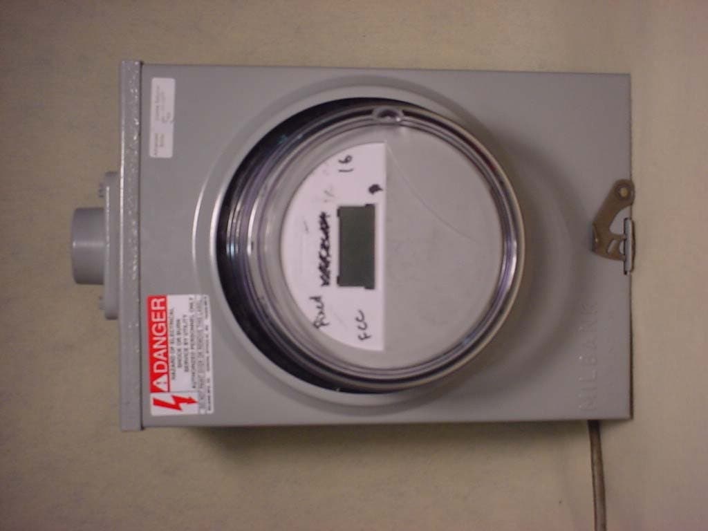
F9CC1SA
Apr 14, 2004Electricity Meter with Dual RF Transmitters
Equipment Class
DSS - Part 15 Spread Spectrum Transmitter
F9CSMFMM-1
Nov 14, 2002Wireless LAN Radio
Equipment Class
DSS - Part 15 Spread Spectrum Transmitter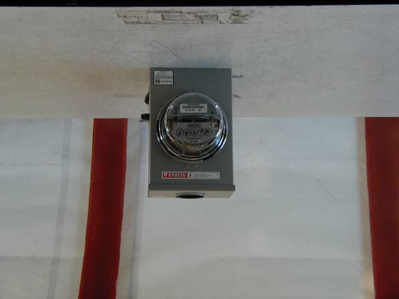
F9C-CBAMM
May 03, 2002Utility Meter Transmitter
Equipment Class
DSS - Part 15 Spread Spectrum Transmitter
F9CC1C-3
Apr 30, 2002Wireless Power Meter
Equipment Class
DSS - Part 15 Spread Spectrum Transmitter