F9CC1R-1Utility Meter Reading Transmitter
Schlumberger Sema
Click to zoom
Application Details
- Equipment Class
- DXX - Part 15 Low Power Communication Device Transmitter
- Date of Grant
- Oct 14, 1998
- Application Purpose
- Original Equipment
- Date of Application
- Aug 06, 1998
- Equipment Note
- Utility Meter Reading Transmitter
- Frequency Range
- 910.00000000 - 920.00000000
- Company
- Schlumberger Sema
- Country
- United States
Documents & Files
Document Text
Text extracted from the exhibit documents filed with the FCC. Open a document above to read the original.
Users Manual
Centron Electricity Meter FCC ID: F9CC1R-1 Exhibit 10: Test Setup Photographs Page 50 Exhibit 10 : User's Manual Background The production version of the Centron Electricity Meter will not be made available to Schlumberger customers until February of 1999. The only units that will be made available to Schlumberger customers between now and February, 1999, are Beta test units. Consequently, the Users Manual does not yet exist, and Schlumberger does not expect to create the Users Manual for the Centron Electricity Meter until later this year. However, the FCC compliance statement that Schlumberger expects to include in the Centron Electricity Meter Users Manual is given on the next page. Should you require more information concerning the Centron Electricity Meter Users Manual, please contact Monty Simmons at (864) 843 - 5158. Centron Electricity Meter FCC ID: F9CC1R-1 Exhibit 10: Test Setup Photographs Page 51 FCC Compliance Statement
Cover Letter(s)
47 CFR Part 15 Subpart C Certification Report Schlumberger Electricity Meter (Centron solid state single-phase electricity meter) FCC ID: F9CC1R-1 Report Number: 980528SC1 Test Start Date: May 21, 1998 Test Engineer: Monty Simmons Testing Laboratory Signature Approvals ___________________________________________________________________________________________________ Report Prepared By: Monty Simmons, Certification SpecialistDate ___________________________________________________________________________________________________ Report Approved By: Pryor McGinnis, PresidentDate The test results presented in this report relate only to the items tested as identified within the body of this report. This report does not constitute any endorsement of the product by the US Government or NIST. This report may be reproduced in full only. Partial reproduction may only be done with the written consent of Compliance Test Laboratories, Inc. NVLAP LAB CODE 200237- 0 TABLE OF CONTENTS Exhibit 1: Cover Letters 2 Section 1.00: Cover Letter 2 Section 1.01: Confidentiality Request 3 (A) Schlumberger - General Request 3 (B) CTL - Specific Request 4 Section 1.02: Agent Authorization / Anti-Drug Abuse Statement 5 Exhibit 2: FCC ID Label Information 7 Section 2.00: FCC ID Label Location Photographs 7 (A) Front View of Centron RMR Meter 7 (B) Centron RMR Meter Cover with FCC ID Number 8 (C) Centron RMR Meter - Glass and Plastic Cover 9 (D) Close-Up View of RMR Board and LCD Display10 (E) RMR Board - Front View - FCC Compliance Statement / FCC ID Number11 Section 2.01: FCC Information 12 (A) RMR Board with FCC ID Number / FCC Art Work12 Exhibit 3: External Photographs 14 Section 3.00: EUT External Photographs14 (A) Centron RMR Meter - Front View14 (B) Centron RMR Meter - Back View15 Exhibit 4: Functional Block Diagram 17 Section 4.00: Centron Electricity Meter Functional Block Diagram17 Exhibit 5: Centron AMR Schematics 19 (A) Power Supply Schematic19 (B) RF Schematic20 (C) Digital Schematic21 Exhibit 6: Report of Measurements 23 Section 6:00: Introduction23 (A) Test Facility Qualifications23 (B) Standards Referenced24 (C) Electromagnetic Emissions Test Results Summary24 (i)Conducted Emissions - Passed: 9.6dB margin24 (ii)Unintentional Electric-Field Radiated Emissions - Passed: 12.4dB margin24 (iii) Intentional Microwave Radiated Emissions - Passed24 Section 6.01: Equipment Under Test25 (A) EUT Description 25 (B) Support Equipment / Cables25 (i)RF Transparent Test Fixture25 (ii) I/O Cables25 (C) Mode of Operation25 (D) EMC Design Modifications25 Section 6.02: Test Procedure26 (A) In General26 (B) Conducted Electromagnetic Emissions26 (i)Calculations27 (ii) Test Equipment Description & Calibration Information27 (iii) Conducted Emissions Measured Data28 (iv) Conducted Emissions - Graphical Representation 29 (C) Unintentional Electric-Field Radiated Emissions30 (i)Calculations30 (ii) Ambient Noise Level 31 (iii) Test Equipment Description & Calibration Information31 (iv) Radiated Emissions Data32 (v)Unintentional Radiated Electric-Field: Graphical Representation33 (D) Microwave Radiated Emissions34 (i)Test Site Used34 (ii) Special Test Equipment Used34 (iii) Test Procedure35 (iv) Calculations35 ♦ Conversion Factor V dB μV to P dB m 35 ♦ Duty Cycle Correction35 ♦ Conversion Factor V dB μV to P dB m : Considering Duty Cycle35 ♦ FCC Limit Correction via 47 CFR 15.24935 (v) Microwave Radiated Emissions Data37 Exhibit 7: Test Setup Photographs 38 (A) Conducted Emissions Test Setup38 (B) Radiated Emissions Test Setup - Back View39 (C) Radiated Emissions Test Setup - Front View40 Exhibit 8: Internal Photographs 42 (A) Centron RMR Meter - Glass and Plastic Cover Removed42 (B) Close-Up View of RMR Board and LCD Display43 (C) RMR Board - Front View - FCC Compliance Statement / FCC ID Number44 (D) RMR Board - Back View45 (E) Metrology Board - Front View46 (F) Metrology Board - Back View47 (G) Meter Base - Front Side48 Exhibit 9: Operational Description 49 Exhibit 10: Users Manual 50 Centron Electricty Meter - Exhibit One: FCC ID Label FCC ID: F9CC1R-1 Page 3 Exhibit 1 : Cover Letters Section 1.00 : Cover Letter August 10, 1998 Federal Communicatio n Co mmission Equipment Approval Services 7435 Oakland Mills Road Columbia, Maryland 21046 (301) 725-1585 Fax : (301) 344 2050 Subject: Form 731 Confirmation Number: EA91296; FCC ID: F9CC1R-1 To whom it may concern: Transmitted herewith, on behalf of Schlumberger Industries, Inc., is an application on FCC Form 731 for Certification of a Part 15 Subpart C (47 CFR §15.249) RF electricity meter. The application was transmitted to the FCC via the Internet remittance process. The Form 731 Confirmation Number is EA91296. A Form 159, along with one check in the amount of $1,025.00 covering the applicable certification fees and a request for confidentially fee of $130.00 has also be submitted. In accordance with Section 2.1033 (b)(9), please be advised that this application is being submitted pursuant to the Commission's new Part 15, as adopted in Gen. Docket No. 87-389. Sho uld yo u require any further infor matio n co ncerni ng this application, please contact me a nyti me via any of the following methods: • Phone: (864) 843 – 5158 or 0303 • Fax: (864) 843 – 1812 • Email: [email protected] Best Regards, William Monty Simmons Certification Specialist Compliance Test Laboratories, Inc. Centron Electricty Meter - Exhibit One: FCC ID Label FCC ID: F9CC1R-1 Page 4 Section 1.01 : Confidentiality Request (a) Schlumberger - General Description Centron Electricty Meter - Exhibit One: FCC ID Label FCC ID: F9CC1R-1 Page 5 (b) CTL - Specific Description August 10, 1998 Federal Communication Commission Equipment Approval Services P.O. Box 358315 Pittsburg, PA 15251-5312 (301) 725 - 1585 Fax : (301) 344 - 2050 Subject: More Specific Request for Confidentiality; FCC ID: F9CC1R-1 To whom it may concern: Listed below is a list of Exhibits for which the request for confidentiality is applica…
Text truncated - open the document above for the full version.
External Photos
Centron Electricity Meter - FCC ID: F9CC1R-1 Exhibit 2: External Photos Page 13 Table of Contacts Exhibit Three EXHIBIT 3 : EXTERNAL PHOTOGRAPHS 14 S ECTION 3.00 : EUT E XTERNAL P HOTOGRAPHS 14 ( A )C ENTRON RMR M ETER - B ACK V IEW 14 ( B )C ENTRON RMR M ETER - B ACK V IEW 15 Centron Electricity Meter - FCC ID: F9CC1R-1 Exhibit 2: External Photos Page 14 Exhibit 3 : External Photographs Section 3.00 : EUT External Photographs (a) Centron RMR Meter - Back View Centron Electricity Meter - FCC ID: F9CC1R-1 Exhibit 2: External Photos Page 15 (b) Centron RMR Meter - Back View
ID Label/Location Info
Centron Electricty Meter - Exhibit Two: FCC ID Label FCC ID: F9CC1R-1 Page 6 Table of Contents Exhibit Two EXHIBIT 2 : FCC ID LABEL 7 S ECTION 2.00 : FCC ID L ABEL L OCATION P HOTOGRAPHS 7 ( A )F RONT V IEW OF C ENTRON RMR M ETER 7 ( B )C ENTRON RMR M ETER C OVER WITH FCC ID N UMBER 9 ( C )C ENTRON RMR M ETER - G LASS AND P LASTIC C OVER R EMOVED 10 ( D )C LOSE - UP V IEW OF RMR B OARD AND LC D D ISPLAY 11 ( E )RMR B OARD - F RONT V IEW - FCC C OMPLIANCE S TATEMENT / FCC ID NUMBER12 S ECTION 2.01 : FCC I NFORMATION AND ID L ABEL I NFORMATION 13 ( A )RMR B OARD WITH FCC ID N UMBER AND FCC C OMPLIANCE S TATEMENT A RT W ORK 13 Centron Electricty Meter - Exhibit Two: FCC ID Label FCC ID: F9CC1R-1 Page 7 Exhibit 2 : FCC ID Label Section 2.00 : FCC ID Label Location Photographs (a) Front View of Centron RMR Meter FCC ID LabelLocation on EUT Centron Electricty Meter - Exhibit Two: FCC ID Label FCC ID: F9CC1R-1 Page 8 Centron Electricty Meter - Exhibit Two: FCC ID Label FCC ID: F9CC1R-1 Page 9 (b) Centron RMR Meter Cover with FCC ID Number FCC ID Number visiblethrough Glass cover ofmeter Centron Electricty Meter - Exhibit Two: FCC ID Label FCC ID: F9CC1R-1 Page 10 (c) Centron RMR Meter - Glass and Plastic Cover Removed Notice FCC Statement.Close-up View of this statement on nextphoto. Centron Electricty Meter - Exhibit Two: FCC ID Label FCC ID: F9CC1R-1 Page 11 (d) Close-up View of RMR Board and LCD Display Notice FCC IDNumber Centron Electricty Meter - Exhibit Two: FCC ID Label FCC ID: F9CC1R-1 Page 12 (e) RMR Board - Front View - FCC Compliance Statement / FCC ID NUMBER Centron Electricty Meter - Exhibit Two: FCC ID Label FCC ID: F9CC1R-1 Page 13 Section 2.01 : FCC Information and ID Label Information (a) RMR Board with FCC ID Number and FCC Compliance Statement Art Work
Internal Photos
Centron Electricity Meter - FCC ID: F9CC1R-1 Exhibit 8: Internal Photographs Page 41 Table of Contents Exhibit Eight EXHIBIT 8 : INTERNAL PHOTOGRAPHS 42 ( A )C ENTRON RMR M ETER - G LASS AND P LASTIC C OVER R EMOVED 42 ( B )C LOSE - UP V IEW OF RMR B OARD AND LCD D ISPLAY 43 ( C )RMR B OARD - F RONT V IEW - FCC C OMPLIANCE S TATEMENT / FCC ID NUMBER44 ( D )RMR B OARD - B ACK V IEW 45 ( E )M ETROLOGY B OARD - F RONT V IEW 46 ( F )M ETROLOGY B OARD - B ACK V IEW 47 ( G )M ETER B ASE - F RONT S IDE 48 Centron Electricity Meter - FCC ID: F9CC1R-1 Exhibit 8: Internal Photographs Page 42 Exhibit 8 : Internal Photographs (a) Centron RMR Meter - Glass and Plastic Cover Removed Notice FCC Statement.Close-up View of this statement onnext photo. Centron Electricity Meter - FCC ID: F9CC1R-1 Exhibit 8: Internal Photographs Page 43 (b) Close-up View of RMR Board and LCD Display Notice FCC IDNumber Centron Electricity Meter - FCC ID: F9CC1R-1 Exhibit 8: Internal Photographs Page 44 (c) RMR Board - Front View - FCC Compliance Statement / FCC ID NUMBER Centron Electricity Meter - FCC ID: F9CC1R-1 Exhibit 8: Internal Photographs Page 45 (d) RMR Board - Back View Centron Electricity Meter - FCC ID: F9CC1R-1 Exhibit 8: Internal Photographs Page 46 (e) Metrology Board - Front View Centron Electricity Meter - FCC ID: F9CC1R-1 Exhibit 8: Internal Photographs Page 47 (f) Metrology Board - Back View Centron Electricity Meter - FCC ID: F9CC1R-1 Exhibit 8: Internal Photographs Page 48 (g) Meter Base - Front Side
Test Report
Centron RF Electricity Meter - FCC ID: F9CC1R-1 Exhibit 6 : Test Report Page 22 Table of Contents Exhibit Six EXHIBIT 6 : REPORT OF MEASUREMENTS 23 S ECTION 6.00 : I NTRODUCTION 23 ( A )T EST F ACILITY Q UALIFICATIONS 23 ( B )S TANDARDS R EFERENCED 24 ( C )E LECTROMAGNETIC E MISSIONS T EST R ESULTS S UMMARY 24 (i) Conducted Emissions - Passed with a 9.6dB Margin24 (ii) Unintentional Electric-Field Radiated Emissions - Passed with a 12.4dB Margin24 (iii) Intentional Microwave Radiated Emissions - Passed24 S ECTION 6.01 : E QUIPMENT -U NDER T EST 25 ( A )EUT D ESCRIPTION 25 ( B )S UPPORT E QUIPMENT / C ABLES 25 (i) RF Transparent Test Fixture25 (ii) I/O Cables25 ( C )M ODE OF O PERATION 25 ( D )EMC D ESIGN M ODIFICATIONS 25 S ECTION 6.02 : T EST P ROCEDURE 26 ( A )I N G ENERAL 26 ( B )C ONDUCTED E LECTROMAGNETIC E MISSIONS 26 (i) Calculations27 (ii) Test Equipment Description & Calibration Information27 (iii) Conducted Emission Measured Data28 (iv) Conducted Emissions - Graphical Representation of Test Data29 ( C )U NINTENTIONAL E LECTRIC -F IELD R ADIATED E MISSIONS 30 (i) Calculations30 (ii) Ambient Noise Level Within 6 dB of Measured EUT Emission31 (iii) Test Equipment Description & Calibration Information31 (iv) RADIATED EMISSIONS DATA32 (v) Unintentional Radiated Electric-Field Emissions - Graph33 ( D )M ICROWAVE R ADIATED E MISSIONS 34 (i) Test Site Used34 (ii) Special Test Equipment Used34 (iii) Test Procedure34 (iv) Calculations35 ♦ Conversion Factor V dBμV to P dBm 35 ♦ Duty Cycle Correction35 ♦ Conversion Factor V dBμV to P dBm After Compensating for Duty Cycle35 ♦ FCC Limit Correction via 47 CFR 15.24935 (v) Microwave Radiated Emissions Data37 Centron RF Electricity Meter - FCC ID: F9CC1R-1 Exhibit 6 : Test Report Page 23 Exhibit 6 : REPORT OF MEASUREMENTS Section 6.00 : Introduction (a) Test Facility Qualifications Compliance Test Laboratories, Inc. (CTL) has achieved the following listing/accreditations given below. Federal Communications Commissions (FCC) The CTL test facility is listed by the FCC, reference number 31040/PRV – 1300F2, as being a site from which the FCC will accept radiated and conducted emissions data for FCC Class B certification. National Institute of Standards and Technology (NAVLAP) The CTL test facility has achieved NAVLAP accreditation in the area of radiated and conducted emissions as specified below: • International Special Committee on Radio Interference (CISPR) 12/CIS22 : IEC/CISPR 22: 1993: Limits and methods of measurement of radio disturbance characteristics of information technology equipment. • FCC Methods (a) 12/F01: FCC Method – 47 CFR Part 15 – Digital Devices (b) 12/F01a : Conducted Emissions, Power Lines, 450 kHz to 30 MHz (c) 12/F01b : Radiated Emissions • Australian Standards referred to by clauses in AUSTEL Technical Standards (a) 12/T50: AS/NZS 3260: Safety of ITE including Electrical Business Equipment (b) 12/T51: AS/NZS 3548: Electromagnetic Interference Test Results Tractability CTL personnel performed all testing. All measurements are traceable to NIST as measurements were made using: • Calibrated test site w/procedures in accordance with ANSI 63.4 1992 • Calibrated measuring instruments traceable to NIST Centron RF Electricity Meter - FCC ID: F9CC1R-1 Exhibit 6 : Test Report Page 24 (b) Standards Referenced Standards Applicable to EUT • ANSI, Methods of Measurement of Radio-Noise Emissions form Low-Voltage Electrical and Electronic Equipment in the Range of 9kHz to 40GHz , C63.4 (1992). • Title 47 CFR Part 15 , Radio Frequency Devices - Subpart C : Intentional Radiators (October 1, 1997). Standards Applicable to Measurement Procedures • CISPR Specifications for Radio Interference Measuring Apparatus and Measurement Methods , CISPR Publication 16, 2 nd Edition (1996). (c) Electromagnetic Emissions Test Results Summary (i) Conducted Emissions - Passed with a 9.6dB Margin The conducted electromagnetic emissions amplitudes were measured from the EUT at the CTL, Inc. electromagnetic measurement laboratory on May 21, 1998. The test results confirm that the amplitudes of the conducted emissions from the EUT comply with FCC Part 15 Subpart C limits . The smallest margin measured was 9.6dB (0.98MHz) and complies with FCC Part 15 Subpart C limits when CTL's measurement of uncertainty of 2.9dB is taken into consideration. (ii) Unintentional Electric-Field Radiated Emissions - Passed with a 12.4dB Margin The conducted electromagnetic emissions amplitudes were measured from the EUT at the CTL, Inc. electromagnetic measurement laboratory on May 21, 1998. The test results confirm that the amplitudes of the unintentional electric-field emissions from the EUT comply with FCC Part 15 Subpart C limits. The smallest margin measured was 12.4 dB (951.76MHz) and complies with FCC Part 15 Subpart C limits when CTL's measurement of uncertainty of 2.56dB is taken into consideration. (iii) Intentional Microwave Radiated Emissions - Passed The microwave radiated electromagnetic emissions amplitudes were measured at the CTL, Inc. electromagnetic measurement laboratory on May 21, 1998. The test results confirm that the amplitudes of the intentional microwave radiated emissions from the EUT comply with FCC Part 15 Subpart C limits. Centron RF Electricity Meter - FCC ID: F9CC1R-1 Exhibit 6 : Test Report Page 25 Section 6.01 : Equipment-Under Test (a) EUT Description The Equipment Under Test (EUT) is the Schlumberger Centron Electricity Meter as described below: • Manufacturer: Schlumberger Electricity • Model Number : Centron with RMR. • Serial Number: 14915930 (b) Support Equipment / Cables (i) RF Transparent Test Fixture • Manufacturer: Schlumberger Electricity • Model Number : N/A. Unique Fixture designed specifically for EMI testing. • Serial Number: N/A (ii) I/O Cables None (c) Mode of Operation • The EUT was operating in its normal operating mode, as specified in §2.2 of this document, during conducted and unintentional radiated emissions testing. • Duri…
Text truncated - open the document above for the full version.
Test Report
Centron RF Electricity Meter : FCC ID: F9CC1R-1 Additional Information Page 1 of 9 September 30, 1998 Rich Fabina, Engineer Federal Communication Commission Equipment Approval Services 7435 Oakland Mills Road Columbia, Maryland 21046 (301) 725-1585 x 220Fax: (301) 344 2050 Subject: 731 Confirmation Number EA91296; Correspondence ID : 3549 Mr. Fabina: The additional information requested, (Correspondence ID: 3549), for the application requesting FCC ID: F9CC1R-1, and having Form Confirmation Number EA91296, should be contained within this document. Should you require any further information concerning this application, please contact me anytime via any the following methods: • Phone : (864) 843 – 5158 or 0303 • Fax: (864) 843 – 1812 • Email : [email protected] Best Regards, William Monty Simmons Certification Specialist Compliance Test Laboratories, Inc. Centron RF Electricity Meter : FCC ID: F9CC1R-1 Additional Information Page 2 of 9 ISSUE ONE : EMISSION TESTING THE REQUEST 1. In accordance with Section 15.31(m) of the FCC Rules, since this transmitter operates over a frequency range of 10 MHz, provide test data with it operating on two channels, a high channel and a low channel. You provided test data on one channel, but I don't know if it's acceptable (See item 2 below). 2. The hopping for this transmitter must be stopped during radiated emissions testing to simplify the measurements. Please confirm that the hopping was stopped for the radiated emission measurements submitted on 915 MHz. If the hopping was not stopped, please remeasure radiated emissions with the hopping stopped on two channels as requested in item 1. If the hopping cannot be stopped, you will have to describe the hopping sequence, the channel dwell time and the radiated emission test procedures is sufficient detail to enable me to determine that you have maximized the emissions from this transmitter for the two channels that must be measured. REPLY • The Hopping Transmitter was indeed configured to prevent hopping from frequency to frequency and forced to continually transmit at 915MHz. • Additional test data at 918 MHz is supplied in Attachment A of this reply. Centron RF Electricity Meter : FCC ID: F9CC1R-1 Additional Information Page 3 of 9 ISSUE TWO : TRANSMITTER SCHEMATICS THE REQUEST 3. Submit legible schematic diagrams of this transmitter. I have done everything that I can do to read them and they are simply unreadable as originally submitted. REPLY Three JPEG files were uploaded at the same time this text file was uploaded. These JPEG files contain images of the schematic diagrams you requested. Centron RF Electricity Meter : FCC ID: F9CC1R-1 Additional Information Page 4 of 9 ISSUE THREE : TYPE OF TRANSMITTER THE REQUEST 4. Confirm that this transmitter operates in accordance with Section 15.249 of the FCC Rules and does not operate as a spread spectrum transmitter in accordance with Section 15.247 of the Rules. REPLY • The EUT described in the report for requested FCC ID F9CC1R-1 is indeed a hopping transmitter that operates in accordance with Section 15.249 of the FCC Rules. • In addition, the manufacturer of the EUT indicates that the EUT shall be operated in accordance to Section 15.249. Centron RF Electricity Meter : FCC ID: F9CC1R-1 Additional Information Page 5 of 9 ISSUE FOUR : CONFIDENTIALLY REQUEST THE REQUEST 5. Confidentiality of the block and schematic diagrams has been requested, but one other exhibit in the application was marked confidential by you. Please confirm that only the block and schematic diagrams require confidentiality. THE REPLY Confidentiality is requested only for the Block and Schematic diagrams. Centron RF Electricity Meter : FCC ID: F9CC1R-1 Additional Information Page 6 of 9 Attachment A : Additional Emission Measurements 1 Microwave Radiated Emissions 1.1 Test Site Used The microwave radiated electromagnetic emission amplitudes, between 900 MHz and 10 GHz, were acquired with the EUT setup on the CTL OATS. At frequencies where ambient noise levels prevented accurate data acquisition on the CTL OATS, the measurements were acquired in the three- meter semi-anechoic chamber. 1.2 Special Test Equipment Used Special test equipment used to acquire the test data is given below. Please refer to the table in Section 6.3.2 for more detailed information. • For frequencies between 1GHz and 18GHz, the Spectrum Technologies Horn Antenna was used. • For frequencies above 1GHz, the HP 8449B preamplifier was used. 1.3 Test Procedure The EUT was setup on a RF transparent table that rests on an EMCO turntable capable of rotating the EUT from 0 to 360 degrees. Cables were oriented to maximize the field strength amplitudes. The receiving antenna was set to fixed height of 1-meter during the test (line of sight). The test distance on the OATS and in the semi-anechoic chamber was three meters. Measurements were manually acquired via the following test procedure: (1) To facilitate easier and more accurate data acquisition, modify the EUT so that it transmits continuously. (2) Determine the fundamental frequency, and the first ten harmonics. (3) Tune the receiver to the frequency of interest; (a) Setup measurement instrumentation in proper measurement mode; (b) Place the antenna in the horizontal position; (c) Rotate EUT and record the maximum emission level detected, antenna height, antenna polarization, and turntable angle; (d) Place the antenna in the vertical position and repeat step (c); (e) Return to step (3) and repeat for each harmonic of interest; (f) Create a report presenting the test results; Centron RF Electricity Meter : FCC ID: F9CC1R-1 Additional Information Page 7 of 9 1.4 Calculations The calculation process for intentional microwave radiated emissions is as indicated below. The microwave emissions were measured in power (dBm) rather than field strength (dBuV). The dBm power reading for the EUT described is converted to dBuV by adding a conversion factor of 76.3 (in a 50- Σ …
Text truncated - open the document above for the full version.
Test Setup Photos
Centron Electricity Meter - FCC ID: F9CC1R-1 Exhibit 7: Test Setup Photographs Page 38 Exhibit 7 : Test Setup Photographs Conducted Emissions Test Setup Centron Electricity Meter - FCC ID: F9CC1R-1 Exhibit 7: Test Setup Photographs Page 39 Radiated Emissions Test Setup - Rear View Centron Electricity Meter - FCC ID: F9CC1R-1 Exhibit 7: Test Setup Photographs Page 40 Radiated Emissions Test Setup - Front View
Contact Information
Applicant
Lee Littlejohn(Compliance Engineer)
Technical Contact
Compliance Test Laboratories, Inc.Monty Simmons, Esq.
[email protected](864) 843 - 5158
Liberty, South Carolina · United States
Non-Technical Contact
Schlumberger ElectricityBill Larsen
[email protected](864) 638 - 4934
Test Firm
Advanced Compliance SolutionsPryor McGinnis
Technical Specifications
| # | Rule Parts | Frequency Range | Power Output |
|---|---|---|---|
| 1 | 15C | 910 MHz - 920 MHz | - |
Other Applications from Schlumberger Sema

F9CC1A-1
May 12, 2004ELECTRICITY METER WITH DUAL RF TRANSMITTERS
Equipment Class
DXX - Part 15 Low Power Communication Device Transmitter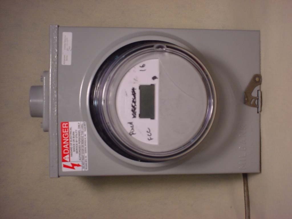
F9CC1SA
Apr 14, 2004Electricity Meter with Dual RF Transmitters
Equipment Class
DSS - Part 15 Spread Spectrum Transmitter
F9CSMFMM-1
Nov 14, 2002Wireless LAN Radio
Equipment Class
DSS - Part 15 Spread Spectrum Transmitter
F9C26-0288
Aug 27, 2002BLT 3 LAN Transceiver
Equipment Class
DSS - Part 15 Spread Spectrum Transmitter
F9C-CBAMM
May 03, 2002Utility Meter Transmitter
Equipment Class
DSS - Part 15 Spread Spectrum Transmitter