F9CR300C-1Low Power Meter Telemetry Transmitter
Schlumberger Sema
Click to zoom
Application Details
- Equipment Class
- DXX - Part 15 Low Power Communication Device Transmitter
- Date of Grant
- Mar 25, 2001
- Application Purpose
- Original Equipment
- Date of Application
- Mar 25, 2001
- Equipment Note
- Low Power Meter Telemetry Transmitter
- Frequency Range
- 912.00000000 - 918.00000000
- Company
- Schlumberger Sema
- Country
- United States
Documents & Files
Document Text
Text extracted from the exhibit documents filed with the FCC. Open a document above to read the original.
Users Manual
FCC ID: F9CR300C-1 SECTION 6 USER'S MANUAL FCC ID: F9CR300C-1
Cover Letter(s)
FCC ID: F9CR300C-1
Cover Letter(s)
FCC ID: F9CR300C-1
Cover Letter(s)
American Telecommunications Certification Body Inc. 6731 Whittier Ave, McLean, VA 22101 March 1, 2001 Tim Johnson U.S. Technologies FCC ID: F9CR300C-1 Tim, Just a few comments on your Application: 1.) Please examine Section 2.9 on pp. 24 and 25 of test report. A 30.7 dB correction is applied to radiated spurious emissions. This is incorrect – corrections greater than 20dB cannot be applied. 2.) The sentence in 2.11 doesn’t make sense. I don’t know what you are trying to say. 3.) Please confirm if the equipment was tested while in the CW state. 4.) Section 2.8 incorrectly refers to 15.247. 5.) The Operational Description attempts to support modular approval. Please provide a more complete description as to how it meets the modular requirements. This should ideally be in the form of an Attestation. 6.) What is the similarities / differences between the differing meter models? 7.) I have some problems with the label. The “two part” label [15.19(a)(3)] will never be seen by the end user unless he disassembles his electric meter. This is an unlikely event. The device is larger than the palm of your hand, therefore I expect there should be easily enough “real estate” to place label on outside. 8.) In addition, if “retrofitting” is permitted, how does the Applicant propose to meet the labeling requirements? Hope this helps. Talk to you soon. William H. Graff Examining Engineer Vice President of Engineering The items indicated above must be submitted before processing can continue on the above referenced application. Failure to provide the requested information within 30 days of the original e-mail date may result in application dismissal pursuant to Section 2.917(c). Correspondence should be considered part of the permanent submission and may be viewed from the Internet after a Grant of Equipment Authorization is issued. Please do not reply to this correspondence using the email reply button. In order for your response to be processed expeditiously, you must attach your answers to email correspondence. Reply to the examiner at the email address shown below. Also, please note that partial responses increase processing time and should not be submitted. Any questions about the content of this correspondence should be directed to the e-mail address listed below the name of the sender.
External Photos
FCC ID: F9CR300C-1 SECTION 5 PHOTOGRAPHS FCC ID: F9CR300C-1 PHOTOS OF THE TESTED EUT The following photos are attached: Photo 1.EUT, Front View of Meter as Tested Photo 2.EUT, Rear View of Meter as Tested Photo 3.EUT, Front View of Meter, Plastic Cover Removed Photo 4.EUT, Side View with Plastic Cover Removed Photo 5.EUT, Top View of Meter Board Photo 6.EUT, Top View of Meter Board with LCD Display Removed Photo 7.EUT, Bottom View of Meter Board Photo 8.EUT, Top View of Power Supply Board Photo 9.EUT, Bottom View of Power Supply Board Photo 10.EUT, Top View of Transmitter Board Photo 11.EUT, Bottom View of Transmitter Board FCC ID: F9CR300C-1 Photo 1.EUT, Front View of Meter as Tested FCC ID: F9CR300C-1 Photo 2.EUT, Rear View of Meter as Tested
ID Label/Location Info
FCC ID: F9CR300C-1 SECTION 3 LABELING INFORMATION FCC ID: F9CR300C-1 Labeling on Transmitter Board FCC ID: F9CR300C-1 Labeling on External Meter
Internal Photos
FCC ID: F9CR300C-1 Photo 3.EUT, Front View of Meter, Plastic Cover Removed FCC ID: F9CR300C-1 Photo 4.EUT, Side View with Plastic Cover Removed FCC ID: F9CR300C-1 Photo 5.EUT, Top View of Meter Board FCC ID: F9CR300C-1 Photo 6.EUT, Top View of Meter Board with LCD Display Removed FCC ID: F9CR300C-1 Photo 7.EUT, Bottom View of Meter Board FCC ID: F9CR300C-1 Photo 8.EUT, Top View of Power Supply Board FCC ID: F9CR300C-1 Photo 9.EUT, Bottom View of Power Supply Board FCC ID: F9CR300C-1 Photo 10.EUT, Top View of Transmitter Board FCC ID: F9CR300C-1 Photo 11.EUT, Bottom View of Transmitter Board
Operational Description
FCC ID: F9CR300C-1 GENERAL INFORMATION 1.1Product Description The Equipment Under Test (EUT) is a Schlumberger Resource Management Services, Inc., Model R300C. The R300C is a Centron solid state residential watt-hour meter (with a Time of Use/Demand register) combined with an RF Transmitter Model R300 Demand. The combined RF transmitter and meter are collectively referred to as a model R300C. The R300C periodically transmits the meter reading and an ID number to utility data collectors that may be stationary, handheld, or vehicular mounted. Operation is one way, as the R300 Demand does not receive. The R300C may contain an optional solid state relay output, which is not related to the RF operation. The R300 Demand is a low power frequency hopping spread spectrum RF transmitter, however because the receivers that are used with this transmitter do not meet with the spread spectrum receiver requirements of 15.247, the transmitter has been designed to meet the requirements of 15.249. The R300 Demand physically consists of two small circuit boards. The RF control board has a linear power supply, a microprocessor, and the optional relay output. The RF transmit board has an RF oscillator and a stripline antenna The EUT transmits on 32 different frequencies between 912 to 918 MHz. These frequencies are selected by changing the DC bias in a portion of the transmitter circuitry. Since the frequencies are not digitally controlled, the frequency accuracy of the transmitter will be approximately ±0.5 MHz. Schlumberger plans to sell the R300C as a whole, but the R300 Demand may also be offered as an upgrade to the following model meters: C1ST, C1SL, CN1ST, or CN1SL. Since the differences between the 4 meter models are not considered to affect the transmitter board, a typical model C1ST was selected and used for all testing.
Test Report
March 15, 2001 Mr. Scott Swanson Senior Design Engineer Schlumberger Resource Management Services, Inc. 313-B North Highway 11 West Union, SC 29696 Dear Mr. Swanson: Enclosed please find Schlumberger Resource Management Services, Inc. file copy of the Part 15 Certification Application for the R300C Transmitter. Schlumberger should expect to receive a certification grant for this product within the next 1-2 weeks. If you have any questions, please don't hesitate to call. Thank you for your business. Sincerely, Timothy R. Johnson NARTE Certified EMC Engineer No. EMC-002205-NE Schlumberger Resource Management Services, Inc. FCC Part 15, Certification Application R300C March 15, 2001 MEASUREMENT/TECHNICAL REPORT COMPANY NAME:Schlumberger Resource Management Services, Inc. MODEL:R300C FCC ID:F9CR300C-1 DATE:March 15, 2001 This report concerns (check one): Original grant X Class II change_____ Equipment type: Low Power Transmitter Deferred grant requested per 47 CFR 0.457(d)(1)(ii)? yes_____ No X If yes, defer until:_________________ date N.A. agrees to notify the Commission by N.A. date of the intended date of announcement of the product so that the grant can be issued on that date. Report prepared by: United States Technologies, Inc. 3505 Francis Circle Alpharetta, GA 30004 Phone Number: (770) 740-0717 Fax Number: (770) 740-1508 TABLE OF CONTENTS AGENCY AGREEMENT LETTER OF CONFIDENTIALITY SECTION 1 GENERAL INFORMATION 1.1Product Description 1.2Related Submittal(s) SECTION 2 TESTS AND MEASUREMENTS 2.1Configuration of Tested EUT 2.2Test Facility 2.3Test Equipment 2.4Modifications 2.5Test Procedure and Results 2.6Antenna Description 2.7Field Strength of Fundamental 2.8Peak Radiated Spurious Emissions 2.9Average Radiated Spurious Emissions 2.10Power Line Conducted Emissions for Transmitter 2.11Radiated Emissions for Digital Device & Receiver (if Applicable) 2.12Power Line Conducted for Digital Device & Receiver (if Applicable) SECTION 3 LABELING INFORMATION SECTION 4 BLOCK DIAGRAM(S)/ SCHEMATIC(S) SECTION 5 PHOTOGRAPHS SECTION 6 USER'S MANUAL FCC ID: F9CR300C-1 LIST OF FIGURES AND TABLES FIGURES 1)Test Configuration 2) Photograph(s) for Spurious and Digital Device Emissions 3) Peak Power Output TABLES 1)EUT and Peripherals 2) Test Instruments 3) Field Strength of Fundamental 4) Peak Radiated Spurious Emissions 5) Average Radiated Spurious Emissions 6) Conducted Emissions Data (Transmitter) 7) Radiated Emissions Data (Digital Device) 8) Conducted Emissions Data (Digital Device) FCC ID: F9CR300C-1 SECTION 1 GENERAL INFORMATION FCC ID: F9CR300C-1 GENERAL INFORMATION 1.1Product Description The Equipment Under Test (EUT) is a Schlumberger Resource Management Services, Inc., Model R300C. The R300C is a Centron solid state residential watt-hour meter (with a Time of Use/Demand register) combined with an RF Transmitter Model R300 Demand. The combined RF transmitter and meter are collectively referred to as a model R300C. The R300C periodically transmits the meter reading and an ID number to utility data collectors that may be stationary, handheld, or vehicular mounted. Operation is one way, as the R300 Demand does not receive. The R300C may contain an optional solid state relay output, which is not related to the RF operation. The R300 Demand is a low power frequency hopping spread spectrum RF transmitter, however because the receivers that are used with this transmitter do not meet with the spread spectrum receiver requirements of 15.247, the transmitter has been designed to meet the requirements of 15.249. The R300 Demand physically consists of two small circuit boards. The RF control board has a linear power supply, a microprocessor, and the optional relay output. The RF transmit board has an RF oscillator and a stripline antenna The EUT transmits on 32 different frequencies between 912 to 918 MHz. These frequencies are selected by changing the DC bias in a portion of the transmitter circuitry. Since the frequencies are not digitally controlled, the frequency accuracy of the transmitter will be approximately ±0.5 MHz. Schlumberger plans to sell the R300C as a whole, but the R300 Demand may also be offered as an upgrade to the following model meters: C1ST, C1SL, CN1ST, or CN1SL. Since the differences between the 4 meter models are not considered to affect the transmitter board, a typical model C1ST was selected and used for all testing. FCC ID: F9CR300C-1 1.2Related Submittal(s)/Grant(s) The EUT will be used with part of a system to send/receive data. The transmitter presented in this report will be used with receivers which have been previously approved. The EUT is subject to the following authorizations: a)Certification as a transmitter b)Verification as a digital device The information contained in this report is presented for the certification & verification authorization(s) for the EUT. FCC ID: F9CR300C-1 SECTION 2 TESTS AND MEASUREMENTS FCC ID: F9CR300C-1 TEST AND MEASUREMENTS 2.1 Configuration of Tested System The sample was tested per ANSI C63.4, Methods of Measurement from Low-Voltage Electrical and Electronic Equipment in the Range of 9 kHz to 40 GHz (1992). Conducted and radiated emissions data were taken with the test receiver or spectrum analyzer's resolution bandwidth adjusted to 9 kHz and 120 kHz, respectively. All measurements are peak unless stated otherwise. The video filter associated with the spectrum analyzer was off throughout the evaluation process. Interconnecting cables were manipulated as necessary to maximize emissions. Interconnecting cables were manipulated as necessary to maximize emissions. A block diagram of the tested system is shown in Figure 1. Test configuration photographs for spurious and fundamental emissions are shown in Figure 2. The sample used for testing was received by U.S. Technologies on January 23, 2001 in good condition. 2.2 Test Facility Testing was performed at US Tech's measurement facility at 3505 Francis Circle, Alpharetta, GA. This site has been f…
Text truncated - open the document above for the full version.
Test Setup Photos
FCC ID: F9CR300C-1 Test Date:January 23, 2001 UST Project:01-0054 Customer:Schlumberger Resource Management Services, Inc. Model:R300C FIGURE 2a Photograph(s) for Spurious and Fundamental Emissions (Front) FCC ID: F9CR300C-1 Test Date:January 23, 2001 UST Project:01-0054 Customer:Schlumberger Resource Management Services, Inc. Model:R300C FIGURE 2b Photograph(s) for Spurious and Fundamental Emissions (Back) FCC ID: F9CR300C-1 Test Date:January 23, 2001 UST Project:01-0054 Customer:Schlumberger Resource Management Services, Inc. Model:R300C FIGURE 2c Photograph(s) for Conducted Emissions
Contact Information
Applicant
Lee Littlejohn(Compliance Engineer)
Technical Contact
U. S. TechnologiesTimothy R Johnson
[email protected]770 740 0717
3505 Francis Circle · Alpharetta, Georgia · United States
Test Firm
US TechSandy McEnery
Technical Specifications
| # | Rule Parts | Frequency Range | Power Output |
|---|---|---|---|
| 1 | 15C | 912 MHz - 918 MHz | - |
Other Applications from Schlumberger Sema

F9CC1A-1
May 12, 2004ELECTRICITY METER WITH DUAL RF TRANSMITTERS
Equipment Class
DXX - Part 15 Low Power Communication Device Transmitter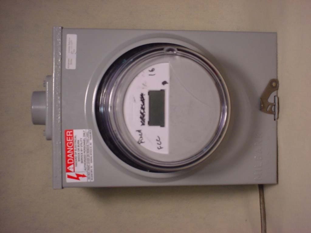
F9CC1SA
Apr 14, 2004Electricity Meter with Dual RF Transmitters
Equipment Class
DSS - Part 15 Spread Spectrum Transmitter
F9CSMFMM-1
Nov 14, 2002Wireless LAN Radio
Equipment Class
DSS - Part 15 Spread Spectrum Transmitter
F9C26-0288
Aug 27, 2002BLT 3 LAN Transceiver
Equipment Class
DSS - Part 15 Spread Spectrum Transmitter
F9C-CBAMM
May 03, 2002Utility Meter Transmitter
Equipment Class
DSS - Part 15 Spread Spectrum Transmitter