F9CR300S-1Low Power Wireless Meter Reader Transmitter
Schlumberger Sema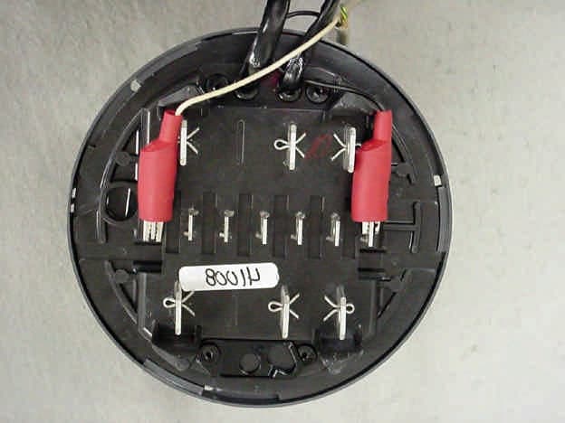
Click to zoom
Application Details
- Equipment Class
- DXX - Part 15 Low Power Communication Device Transmitter
- Date of Grant
- Mar 07, 2002
- Application Purpose
- Original Equipment
- Date of Application
- Mar 07, 2002
- Equipment Note
- Low Power Wireless Meter Reader Transmitter
- Frequency Range
- 910.00000000 - 920.00000000
- Company
- Schlumberger Sema
- Country
- United States
Documents & Files
Document Text
Text extracted from the exhibit documents filed with the FCC. Open a document above to read the original.
Users Manual
FCC ID: F9CR300S-1
Cover Letter(s)
FCC ID: F9CR300S-1
Cover Letter(s)
FCC ID: F9CR300S-1
External Photos
FCC ID: F9CR300S-1 Photo 1.EUT, Front View of Meter as Tested FCC ID: F9CR300S-1 Photo 2.EUT, Rear View of Meter as Tested FCC ID: F9CR300S-1 Photo 3.EUT, Front View of Meter, Plastic Cover Removed
ID Label/Location Info
FCC ID: F9CR300S-1 Labeling on Transmitter Board FCC ID: F9CR300S-1 Labeling on External Meter Units built at the factory that contain the meter and transmitter will be shipped with a label printed to include the FCC ID (see below). Units installed as an option in the field will have a small label installed by the technician performing the upgrade in the field. This label will be placed in the same area shown below
Internal Photos
FCC ID: F9CR300S-1 Photo 4.EUT, View with Electronics Removed FCC ID: F9CR300S-1 Photo 5.EUT, Top View of Digital Pulse Output Board Photograph Not Available FCC ID: F9CR300S-1 Photo 6. EUT, Bottom View of Digital Pulse Output Board FCC ID: F9CR300S-1 Photo 7.EUT, Top View of Register Board with LCD Display FCC ID: F9CR300S-1 Photo 8.EUT, Bottom View of Register Board FCC ID: F9CR300S-1 Photo 9.EUT, Top View of Power Supply Board FCC ID: F9CR300S-1 Photo 10.EUT, Bottom View of Power Supply Board FCC ID: F9CR300S-1 Photo 11.EUT, Top View of Transmitter Board FCC ID: F9CR300S-1 Photo 12.EUT, Bottom View of Transmitter Board
Internal Photos
FCC ID: F9CR300S-1 Photo 4.EUT, View with Electronics Removed FCC ID: F9CR300S-1 Photo 5.EUT, Top View of Digital Pulse Output Board FCC ID: F9CR300S-1 Photo 6. EUT, Bottom View of Digital Pulse Output Board FCC ID: F9CR300S-1 Photo 7.EUT, Top View of Register Board with LCD Display FCC ID: F9CR300S-1 Photo 8.EUT, Bottom View of Register Board FCC ID: F9CR300S-1 Photo 9.EUT, Top View of Power Supply Board FCC ID: F9CR300S-1 Photo 10.EUT, Bottom View of Power Supply Board FCC ID: F9CR300S-1 Photo 11.EUT, Top View of Transmitter Board FCC ID: F9CR300S-1 Photo 12.EUT, Bottom View of Transmitter Board
Operational Description
FCC ID: F9CR300S-1 GENERAL INFORMATION 1.1Product Description The Equipment Under Test (EUT) is a SchlumbergerSema, Inc., Model R300S which is an RF option for the SENTINEL line of meters. The trade name for the meter is SENTINEL. The trade name for the optional broadcast board is the R300. It comes in two models that are physically identical and differ only in the number of unique ID's that are broadcast. A single ID unit is called an R300S and a dual ID unit is called an R300SD. The name SENTINAL and the model R300S or R300SD will be clearly marked on the label. The SENTINEL product line are solid state electricity power meters which Schlumberger currently produces. The basic meter consists of an signal input circuit board, which scales the input voltages and has a switching power supply, permanently connected to register circuit board which does calculations and the display function. The register board has a small linear power supply. There are a few different models of the SENTINAL meter, but the differences are not considered to affect the transmitter board. The R300S is an RF option for the SENTINEL meter which will periodically transmit the meter reading and an ID number to utility data collectors that may be stationary, handheld, or vehicular mounted. The R300S board may also pass signals from the register board to an optional solid state relay output board which is not related to the RF operation. The R300S physically consists of one small circuit board. The RF board has a linear power supply, a microprocessor, an RF oscillator and a stripline antenna. The EUT transmits on different frequencies between 910 to 920 MHz. These frequencies are selected by changing the DC bias in a portion of the transmitter circuitry. The system data collectors' receiver range is 910 to 920 MHz. Each R300S uses approximately 6 MHz of this range. The R300S pseudorandomly hops to a new frequency within its range for each transmitted message. However because the receivers that are used with this transmitter do not meet with the spread spectrum receiver requirements of 15.247, the transmitter has been designed to meet the requirements of 15.249. Operation is one way; the R300S does not receive. The R300S does not allow for customer programming of the RF parameters of a sealed meter. All RF programming and RF tuning of the product will be done by factory trained personnel during the manufacturing process. At that time the R300S is tested, tuned, and programmed in non-volatile memory for operating system parameters and FCC compliance. Schlumberger plans to sell the SENTINAL meter with the R300S as a whole, but it may also be offered as an upgrade to the SENTINAL meters.
Test Report
SchlumbergerSema, Inc. FCC Part 15, Certification Application R300S February 6, 2002 MEASUREMENT/TECHNICAL REPORT COMPANY NAME:SchlumbergerSema, Inc. MODEL:R300S FCC ID:F9CR300S-1 DATE:February 6, 2002 This report concerns (check one): Original grant X Class II change_____ Equipment type: Low Power Transmitter Deferred grant requested per 47 CFR 0.457(d)(1)(ii)? yes_____ No X If yes, defer until:_________________ date N.A. agrees to notify the Commission by N.A. date of the intended date of announcement of the product so that the grant can be issued on that date. Report prepared by: United States Technologies, Inc. 3505 Francis Circle Alpharetta, GA 30004 Phone Number: (770) 740-0717 Fax Number: (770) 740-1508 TABLE OF CONTENTS AGENCY AGREEMENT LETTER OF CONFIDENTIALITY SECTION 1 GENERAL INFORMATION 1.1Product Description 1.2Related Submittal(s) SECTION 2 TESTS AND MEASUREMENTS 2.1Configuration of Tested EUT 2.2Test Facility 2.3Test Equipment 2.4Modifications 2.5Test Procedure and Results 2.6Antenna Description 2.7Field Strength of Fundamental 2.8Peak Radiated Spurious Emissions 2.9Average Radiated Spurious Emissions 2.10Power Line Conducted Emissions for Transmitter 2.11Radiated Emissions for Digital Device & Receiver (if Applicable) 2.12Power Line Conducted for Digital Device & Receiver (if Applicable) SECTION 3 LABELING INFORMATION SECTION 4 BLOCK DIAGRAM(S)/ SCHEMATIC(S) SECTION 5 PHOTOGRAPHS SECTION 6 USER'S MANUAL FCC ID: F9CR300S-1 LIST OF FIGURES AND TABLES FIGURES 1)Test Configuration 2) Photograph(s) for Spurious and Digital Device Emissions 3) Peak Power Output TABLES 1)EUT and Peripherals 2) Test Instruments 3) Field Strength of Fundamental 4) Peak Radiated Spurious Emissions 5) Average Radiated Spurious Emissions 6) Conducted Emissions Data (Transmitter) 7) Radiated Emissions Data (Digital Device) 8) Conducted Emissions Data (Digital Device) FCC ID: F9CR300S-1 SECTION 1 GENERAL INFORMATION FCC ID: F9CR300S-1 GENERAL INFORMATION 1.1Product Description The Equipment Under Test (EUT) is a SchlumbergerSema, Inc., Model R300S which is an RF option for the SENTINEL line of meters. The trade name for the meter is SENTINEL. The trade name for the optional broadcast board is the R300. It comes in two models that are physically identical and differ only in the number of unique ID's that are broadcast. A single ID unit is called an R300S and a dual ID unit is called an R300SD. The name SENTINAL and the model R300S or R300SD will be clearly marked on the label. The SENTINEL product line are solid state electricity power meters which Schlumberger currently produces. The basic meter consists of an signal input circuit board, which scales the input voltages and has a switching power supply, permanently connected to register circuit board which does calculations and the display function. The register board has a small linear power supply. There are a few different models of the SENTINAL meter, but the differences are not considered to affect the transmitter board. The R300S is an RF option for the SENTINEL meter which will periodically transmit the meter reading and an ID number to utility data collectors that may be stationary, handheld, or vehicular mounted. The R300S board may also pass signals from the register board to an optional solid state relay output board which is not related to the RF operation. The R300S physically consists of one small circuit board. The RF board has a linear power supply, a microprocessor, an RF oscillator and a stripline antenna. The EUT transmits on different frequencies between 910 to 920 MHz. These frequencies are selected by changing the DC bias in a portion of the transmitter circuitry. The system data collectors' receiver range is 910 to 920 MHz. Each R300S uses approximately 6 MHz of this range. The R300S pseudorandomly hops to a new frequency within its range for each transmitted message. However because the receivers that are used with this transmitter do not meet with the spread spectrum receiver requirements of 15.247, the transmitter has been designed to meet the requirements of 15.249. Operation is one way; the R300S does not receive. The R300S does not allow for customer programming of the RF parameters of a sealed meter. All RF programming and RF tuning of the product will be done by factory trained personnel during the manufacturing process. At that time the R300S is tested, tuned, and programmed in non-volatile memory for operating system parameters and FCC compliance. Schlumberger plans to sell the SENTINAL meter with the R300S as a whole, but it may also be offered as an upgrade to the SENTINAL meters. FCC ID: F9CR300S-1 1.2Related Submittal(s)/Grant(s) The EUT will be used with part of a system to send/receive data. The transmitter presented in this report will be used with receivers which have been previously approved. The EUT is subject to the following authorizations: a)Certification as a transmitter b)Verification as a digital device The information contained in this report is presented for the certification & verification authorization(s) for the EUT. FCC ID: F9CR300S-1 SECTION 2 TESTS AND MEASUREMENTS FCC ID: F9CR300S-1 TEST AND MEASUREMENTS 2.1 Configuration of Tested System The sample was tested per ANSI C63.4, Methods of Measurement from Low-Voltage Electrical and Electronic Equipment in the Range of 9 kHz to 40 GHz (1992). Conducted and radiated emissions data were taken with the test receiver or spectrum analyzer's resolution bandwidth adjusted to 9 kHz and 120 kHz, respectively. All measurements are peak unless stated otherwise. The video filter associated with the spectrum analyzer was off throughout the evaluation process. Interconnecting cables were manipulated as necessary to maximize emissions. Interconnecting cables were manipulated as necessary to maximize emissions. A block diagram of the tested system is shown in Figure 1. Test configuration photographs for spurious and fundamental emissions are shown in Figure 2. The…
Text truncated - open the document above for the full version.
Test Setup Photos
FCC ID: F9CR300S-1 Test Date:January 16, 2002 UST Project:02-0019 Customer:SchlumbergerSema, Inc. Model:R300S FIGURE 2a Photograph(s) for Spurious and Fundamental Emissions (Front) Test Photographs not Available FCC ID: F9CR300S-1 Test Date:January 16, 2002 UST Project:02-0019 Customer:SchlumbergerSema, Inc. Model:R300S FIGURE 2b Photograph(s) for Spurious and Fundamental Emissions (Back) Test Photographs not Available FCC ID: F9CR300S-1 Test Date:January 16, 2002 UST Project:02-0019 Customer:SchlumbergerSema, Inc. Model:R300S FIGURE 2c Photograph(s) for Conducted Emissions Test Photographs not Available
Contact Information
Applicant
Lee Littlejohn(Compliance Engineer)
Technical Contact
U. S. TechnologiesTimothy R Johnson
[email protected]770 740 0717
3505 Francis Court Circle · Alpharetta, Georgia · United States
Test Firm
US TechSandy McEnery
Technical Specifications
| # | Rule Parts | Frequency Range | Power Output |
|---|---|---|---|
| 1 | 15C | 910 MHz - 920 MHz | - |
Other Applications from Schlumberger Sema

F9CC1A-1
May 12, 2004ELECTRICITY METER WITH DUAL RF TRANSMITTERS
Equipment Class
DXX - Part 15 Low Power Communication Device Transmitter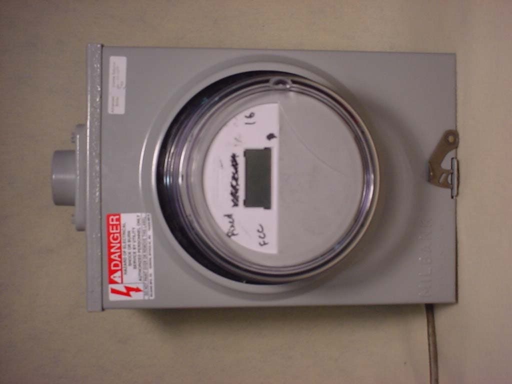
F9CC1SA
Apr 14, 2004Electricity Meter with Dual RF Transmitters
Equipment Class
DSS - Part 15 Spread Spectrum Transmitter
F9CSMFMM-1
Nov 14, 2002Wireless LAN Radio
Equipment Class
DSS - Part 15 Spread Spectrum Transmitter
F9C26-0288
Aug 27, 2002BLT 3 LAN Transceiver
Equipment Class
DSS - Part 15 Spread Spectrum Transmitter
F9C-CBAMM
May 03, 2002Utility Meter Transmitter
Equipment Class
DSS - Part 15 Spread Spectrum Transmitter