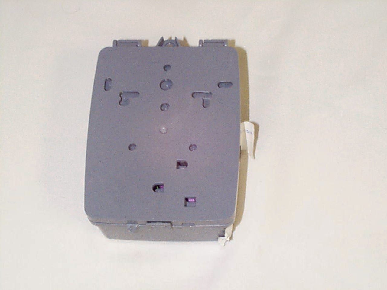
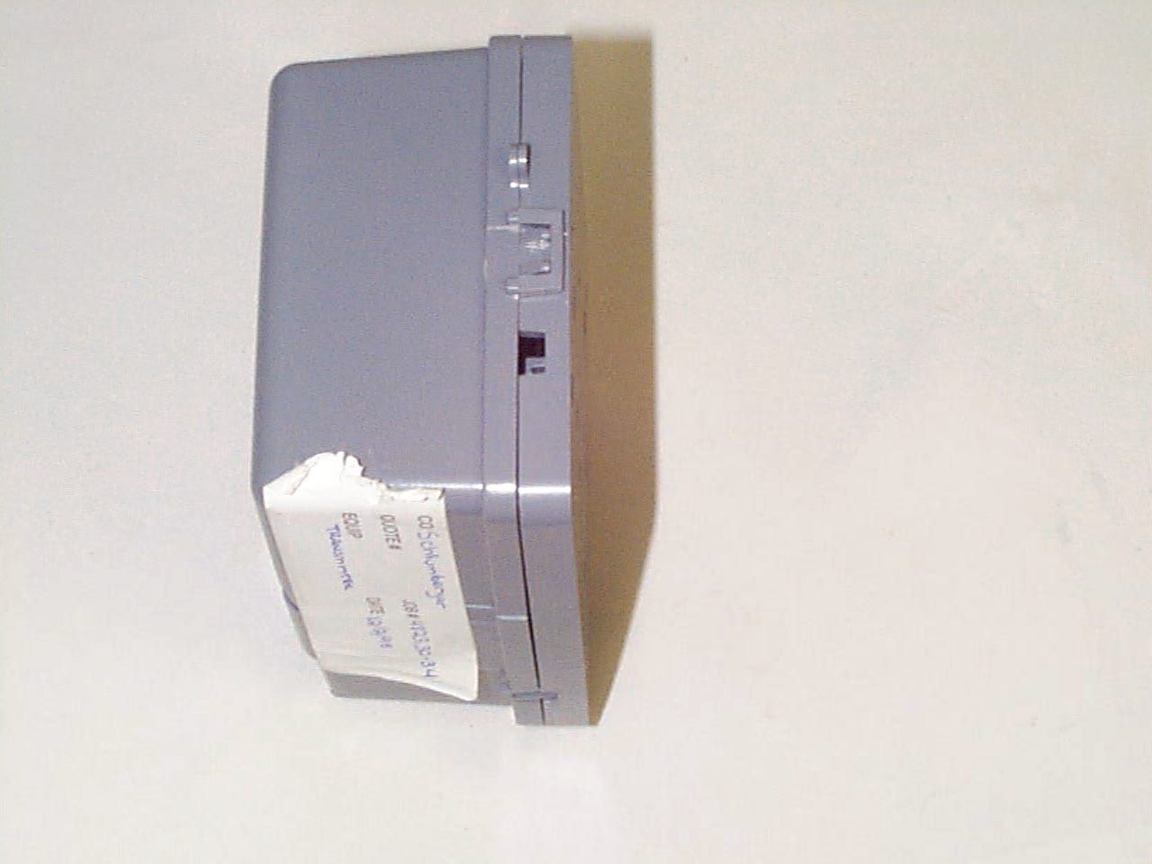
F9CTALSRFW1Meter Reading Transmitter
Schlumberger Sema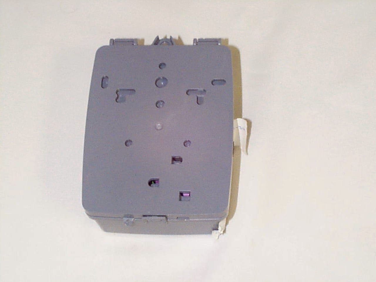
Click to zoom
Application Details
- Equipment Class
- DSS - Part 15 Spread Spectrum Transmitter
- Date of Grant
- Mar 28, 1999
- Application Purpose
- Original Equipment
- Date of Application
- Jan 04, 1999
- Equipment Note
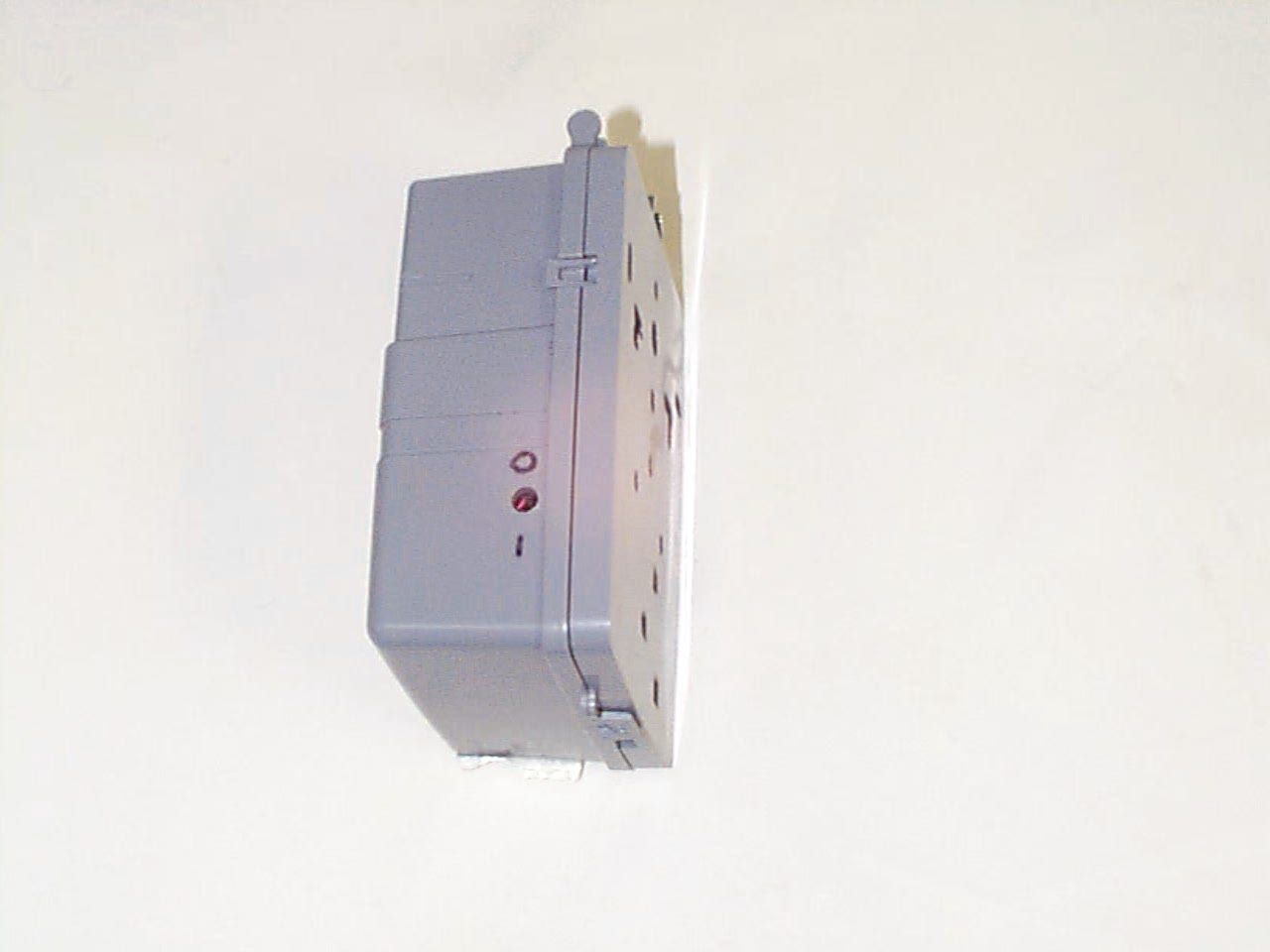
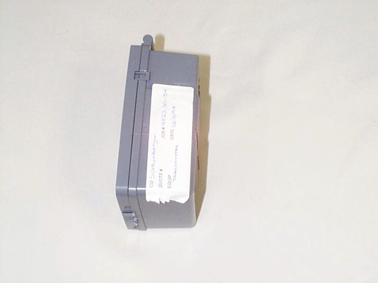
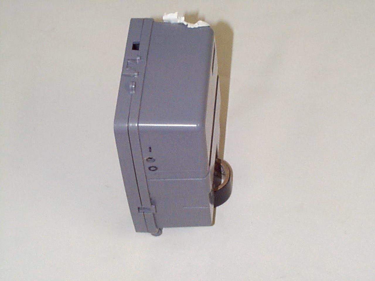
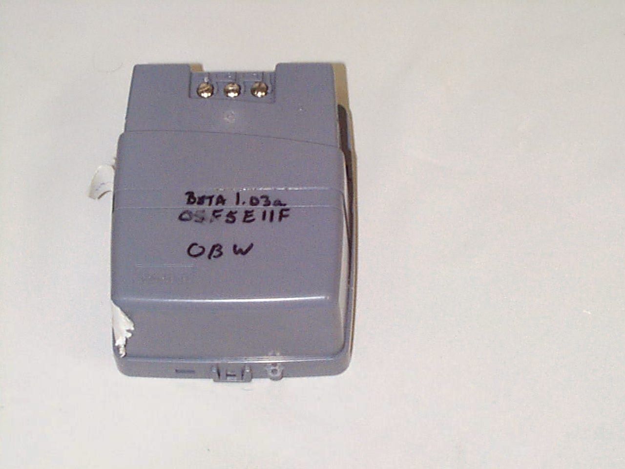
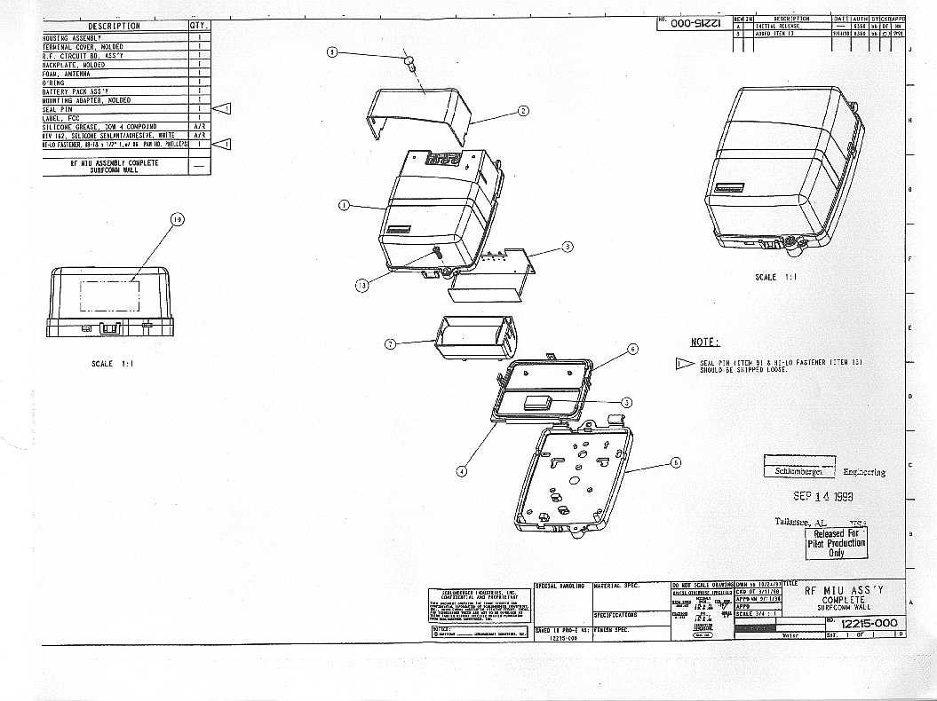
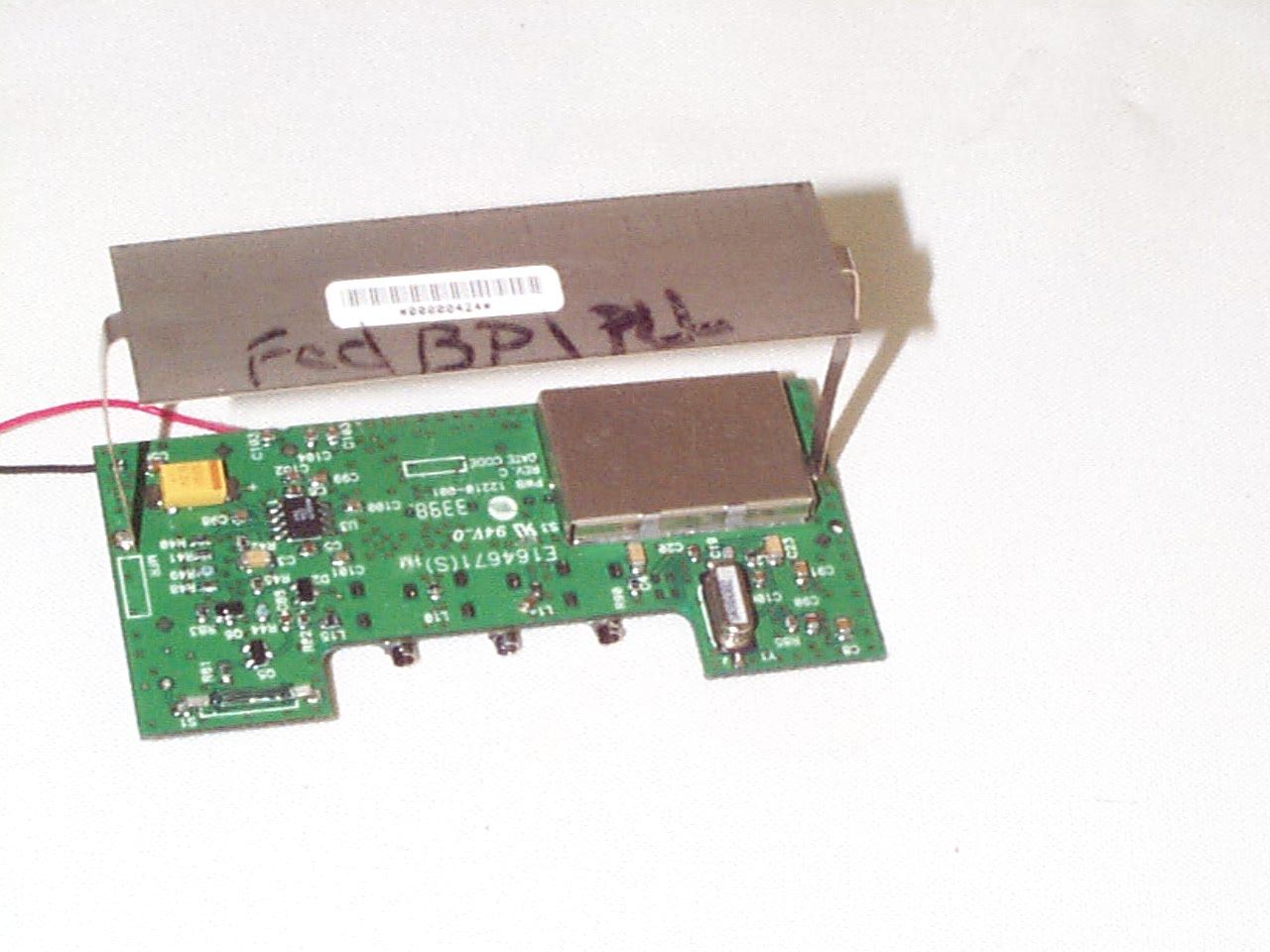
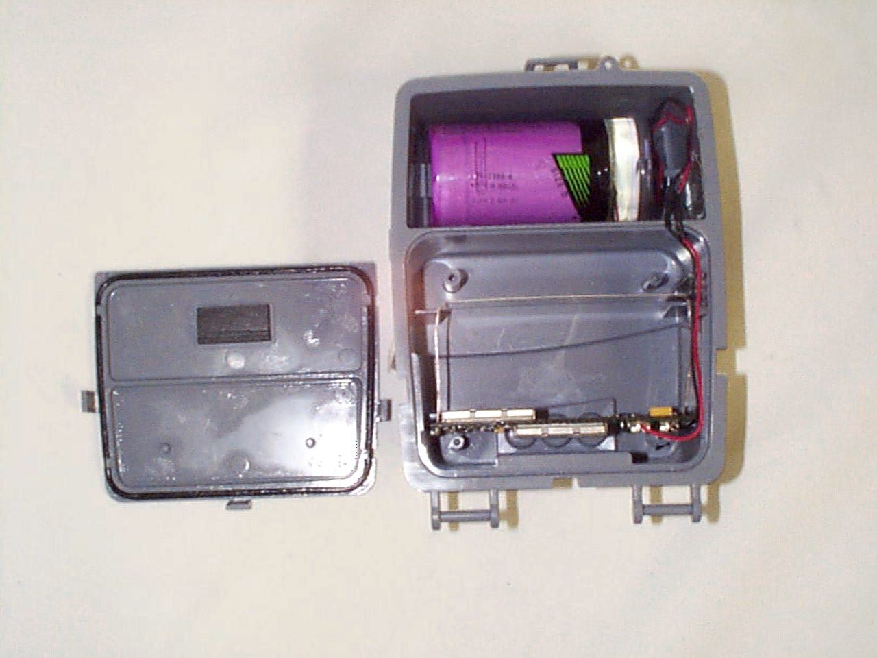
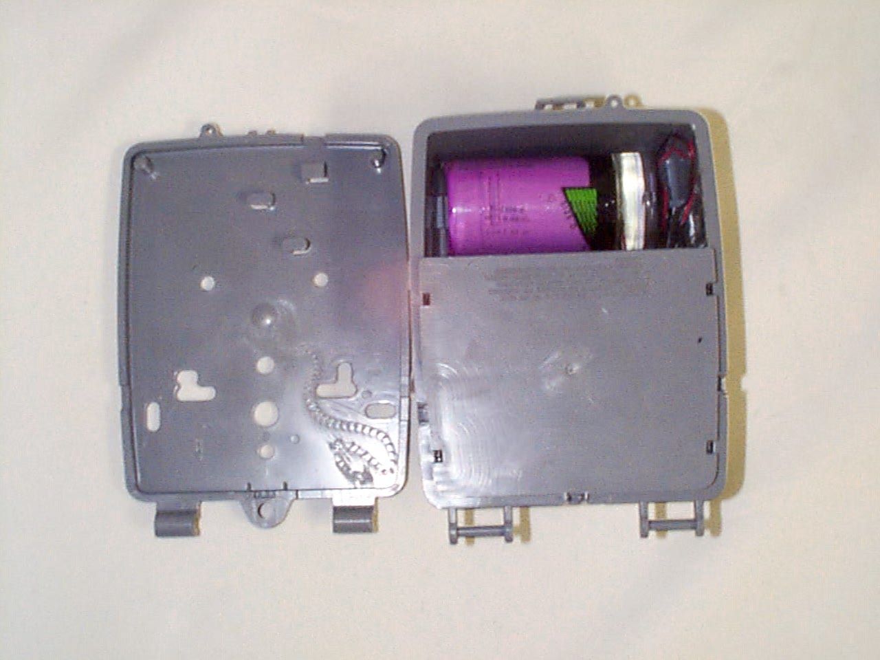
- Meter Reading Transmitter
- Frequency Range
- 911.08000000 - 919.08000000
- Company
- Schlumberger Sema
- Country
- United States
Documents & Files
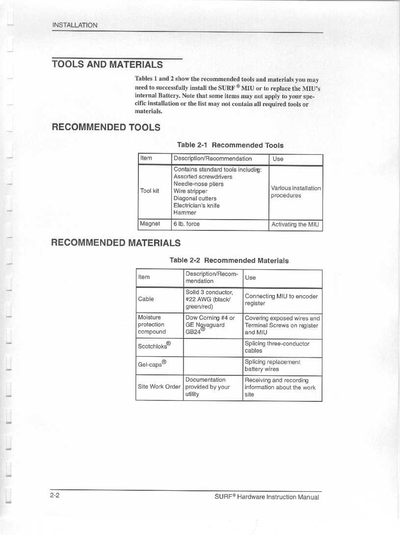
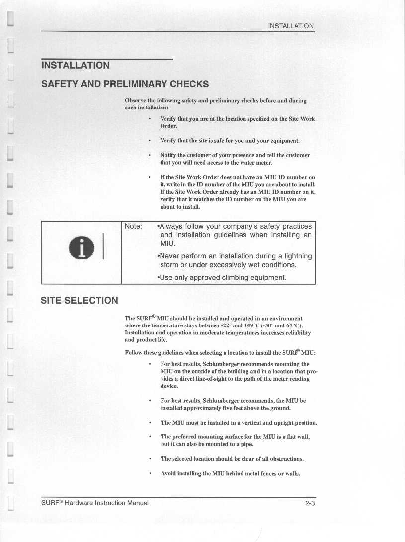
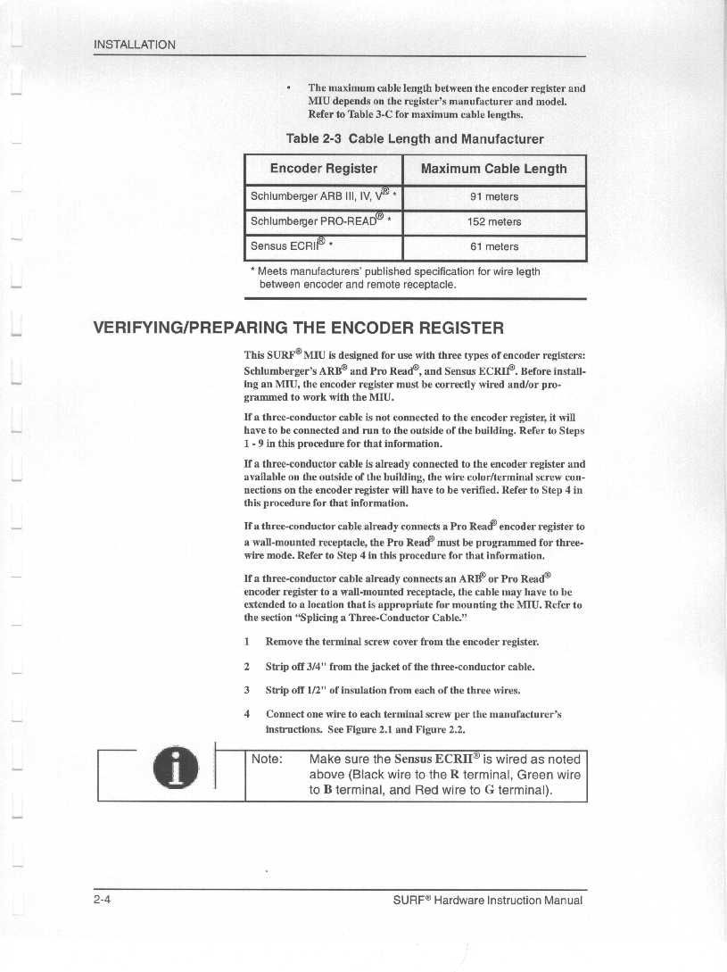
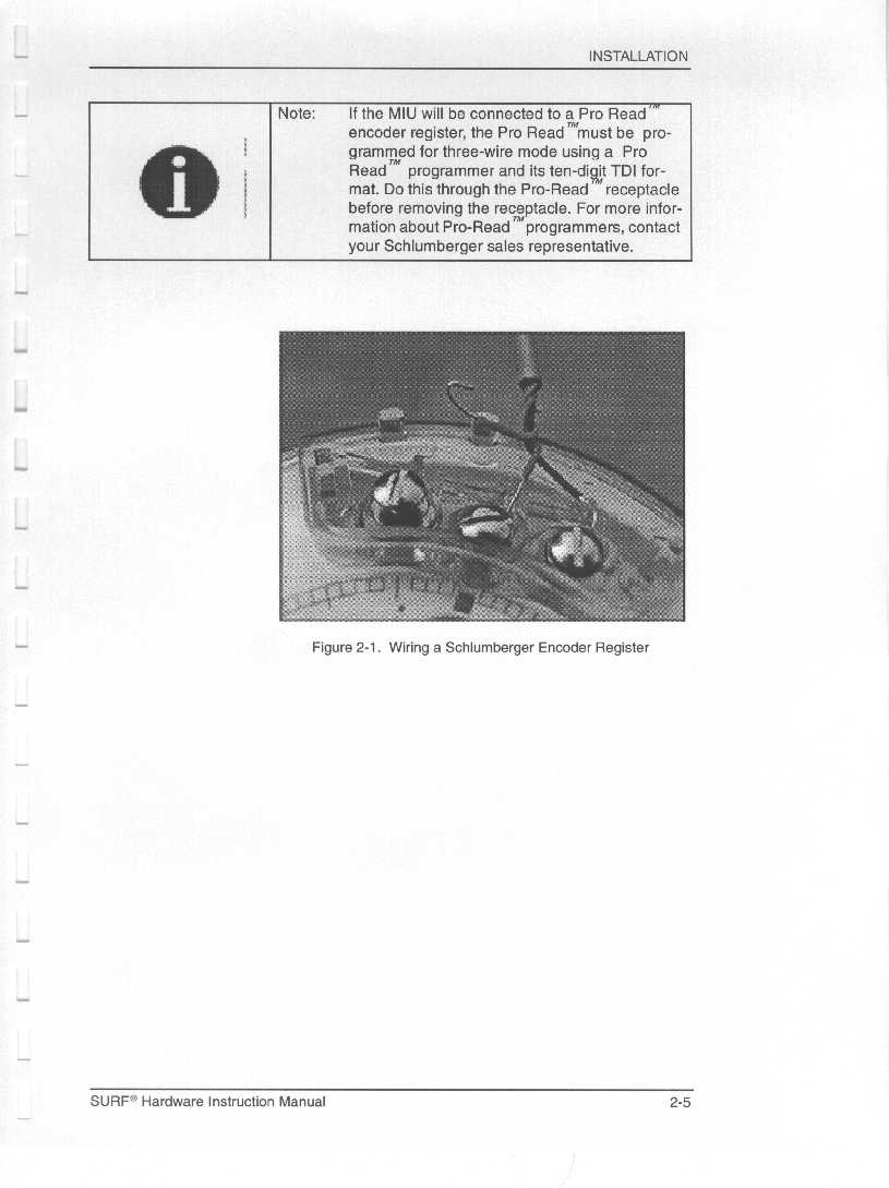
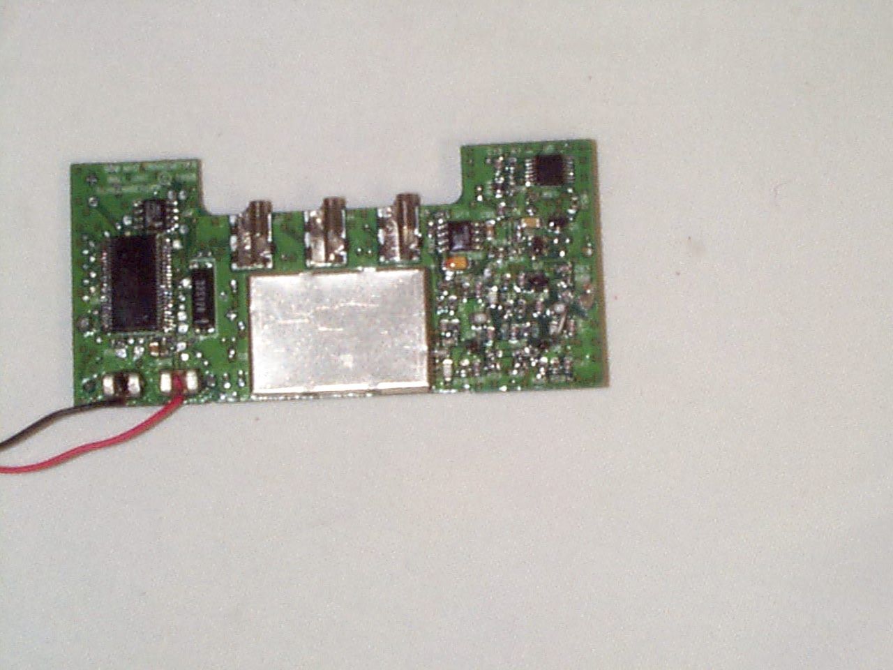
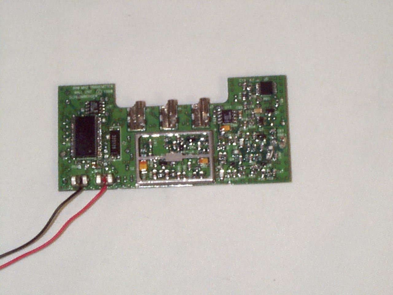
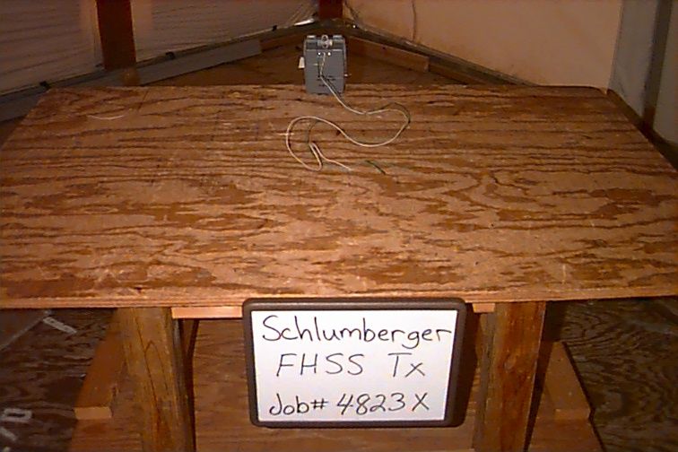
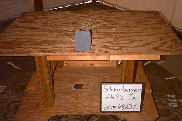
Document Text
Text extracted from the exhibit documents filed with the FCC. Open a document above to read the original.
Operational Description
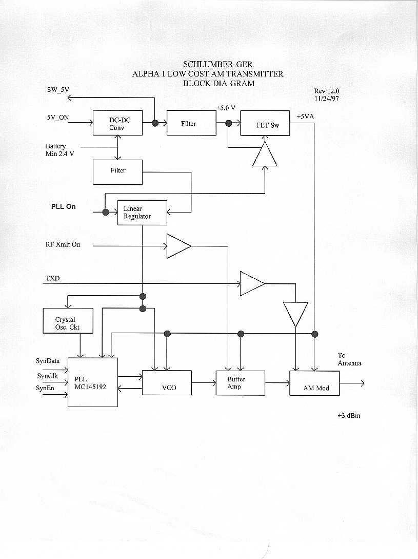
Apex Wireless / Schlumberger Confidential1 HR23x0 Theory of operation 1.1. System Architecture A conventional superheterodyne architecture is used for this receiver. The receiver interface is a standard RS-232 interface. The system architecture is shown in the following block diagram. 130.38 MHz BPF 10.7 MHz BPF 150 KHz BW 10.7 MHz BPF 400 KHz BW 80.7 MHz 2nd LO RSSI Det Wide Band RSSI Det Narrow Band PLL IC Schlumberger Proposed Universal Receiver Block Diag IF AMP IF AMP Frequency Discriminator Mux / ADC Data Detector / Radio Driver uP Atmel AVR PLL Control Lines DDS Synthesizer PLL Ref Freq 8052 uP Interface Logic RS232 Port 1st LO RF 1st IF Radio PCB Digital PCB 2. Receiver Functional Architecture and Design The drawing illustrated above shows the system block diagram The digital section incorporates a DDS synthesizer, which will allow for fast frequency scanning. 2.1. Signal Detection / Frequency Scanning Apex Wireless / Schlumberger Confidential2 Since the receiver has no advance knowledge of the frequency or timing of the transmitter, it must scan the frequency band in search of transmitters. The receiver is able to implement a fast scan rate by locking a conventional LO PLL to a fast scanning direct digital synthesizer (DDS). This technique is implemented as illustrated below: DDS AD9831 16 MHz XTAL Div 0 ms 4.043 MHz 3.986 MHz Fref Fref Microprocessor Digital PCBRad Schlumberger Universal Receiver F Atmel AVR As the drawing above indicates, to incorporate the “fast scan” capability, the receiver uses a DDS synthesizer IC to “drive” our conventional phase locked loop. This technique also allows for an increase in the PLL reference frequency well above the channel spacing (800 KHz nom) , which allows us to use a wide loop bandwidth, and insure good tracking of the input frequency, with little “ringing” on the output frequency. 2.2. Data Detection As is indicated on the Block Diagram, data is detected using a combination of a wide and narrow band IF filter section. The wide band filter section gives us a longer time to make a data/no data determination during the frequency scan. For example, with the wide band filter bandwidth of 400 KHz, a frequency sweep of 10 MHz, and a sweep time of 1.5 ms, the data window will be 400 KHz/10MHz * 1.5ms = 60us. If the data code is guaranteed to have an “on bit” during this window, than it will be possible to determine the presence of a data transmitter. Apex Wireless / Schlumberger Confidential3 Once a data pulse is detected, the sweep will stop and the remaining data bits will be detected. By looking at the frequency discriminator output, we can determine if our local oscillator center frequency is high or low, and estimate the required correction necessary to center it. Once this correction is made, the detector can switch to the narrow band IF channel to achieve an improvement in sensitivity. If it is determined that a transmitter burst has been detected, the frequency and start time of this burst can be stored for a spread spectrum implementation. Both data / no data determination and the data demodulation detection are made using high speed ADC’s closely coupled to the microprocessor. 3. Firmware Design The receiver control operation is split over two processors: the control processor for receiver control and interface to the serial port, and a high-speed decoding processor for frequency control and data demodulation. The first processor is used for Reed-Solomon error correction if that feature is implemented. The decoding processor controls the receiver frequency, including generating a high- speed sweep used to locate potential meter transmitter signals. Once a signal is found in the operating band, the processor locks onto the frequency, using both amplitude and frequency discrimination techniques, in time to sample transmitted data. If the modulation timing is incompatible with the expected transmitter characteristics, the signal is skipped and the search for valid transmitter signals continues. When the incoming data disappears, due to packet completion, the processor frames the data portion and tests it for valid data in either of the two supported formats. If the data is formatted correctly, it is sent to the serial interface processor for transmission. The decoding processor also keeps track of interfering frequencies, so that decoding is not attempted on each scan. This significantly improves the percentage of time that is available to catch a meter signal.
Test Report
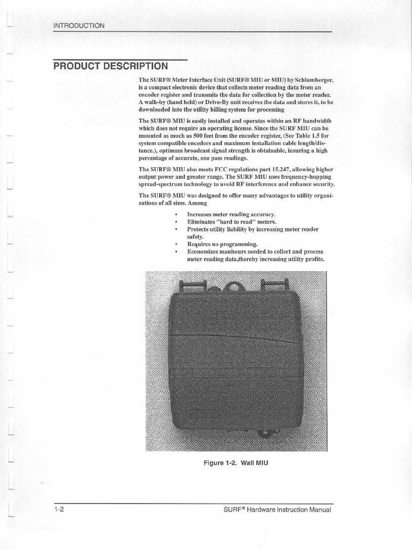
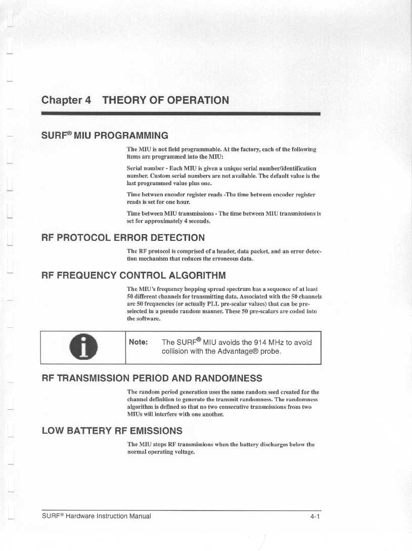
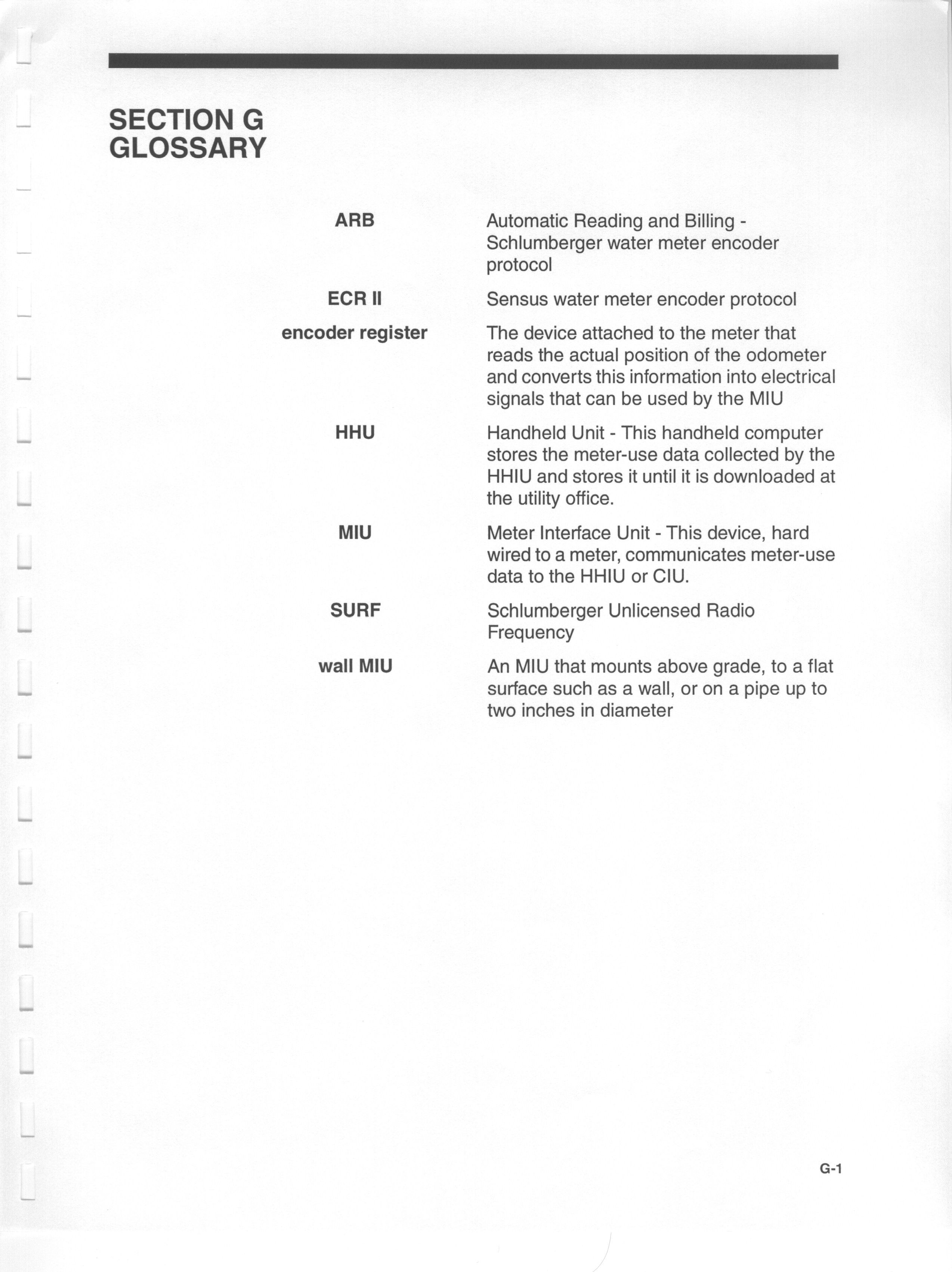
FCC CERTIFICATION TEST REPORT for Schlumberger Industries, Inc. 1600 Alabama Highway 229 Tallassee, AL 36078 FCC ID: F9CTALSRFW1 December 21, 1998 WLL PROJECT #: 4823X This report may not be reproduced, except in full, without the prior written consent of Washington Laboratories, Ltd. Schlumberger Industries, Inc. FCC ID: F9CTALSRFW1 WLL Project #: 4823X i TABLE OF CONTENTS ___________________________________________ Letter of Agency Letter of Confidentiality Statement of Qualifications 1.0INTRODUCTION............................................................................................................................. 4 1.1S UMMARY ........................................................................................................................................ 4 2.0DESCRIPTION OF EQUIPMENT UNDER TEST (EUT) ........................................................... 4 2.1O N - BOARD O SCILLATORS ................................................................................................................ 5 3.0TEST CONFIGURATION............................................................................................................... 5 3.1T ESTING A LGORITHM ...................................................................................................................... 5 3.2C ONDUCTED E MISSIONS T ESTING .................................................................................................... 5 3.3R ADIATED E MISSIONS T ESTING ....................................................................................................... 5 3.3.1Radiated Data Reduction and Reporting ................................................................................ 6 3.4RF A NTENNA C ONDUCTED S PURIOUS E MISSIONS T ESTING ........................................................... 10 3.5C ARRIER B ANDWIDTH T ESTING ..................................................................................................... 14 3.6P OWER O UTPUT T ESTING ............................................................................................................... 14 3.7R ADIO F REQUENCY R ADIATION E XPOSURE ................................................................................... 15 TABLES Table 1.FCC Part 15.247(c) 3 M Radiated Emissions Data Table 2.FCC RF Radiated Spurious Emissions Data Table 3.System Under Test Table 4.Interface Cables Used Table 5.Measurement Equipment Used EXHIBITS Exhibit 1. Occupied Bandwidth Plots Schlumberger Industries, Inc. FCC ID: F9CTALSRFW1 WLL Project #: 4823X 1 Schlumberger Industries, Inc. FCC ID: F9CTALSRFW1 WLL Project #: 4823X 2 Schlumberger Industries, Inc. FCC ID: F9CTALSRFW1 WLL Project #: 4823X 3 Schlumberger Industries, Inc. FCC ID: F9CTALSRFW1 WLL Project #: 4823X 4 FCC CERTIFICATION TEST REPORT for Schlumberger Industries, Inc. FCC ID: F9CTALSRFW1 1.0Introduction This report has been prepared on behalf of Schlumberger Industries, Inc. to support the attached Application for Equipment Authorization. The test and application are submitted for an Intentional Radiator under Section 15.247 of the FCC Rules and Regulations. The Equipment Under Test was a Schlumberger Industries, Inc. Frequency Hopping Spread Spectrum Transmitter, Model: SURF MIU. All measurements herein were performed according to the 1992 version of ANSI C63.4. The measurement equipment conforms to ANSI C63.2 Specifications for Electromagnetic Noise and field Strength Instrumentation. Calibration checks are made periodically to verify proper performance of the measuring instrumentation. All measurements were performed at Washington Laboratories, Ltd. test center in Gaithersburg, MD. Site description and site attenuation data have been placed on file with the FCC's Sampling and Measurements Branch at the FCC laboratory in Columbia, MD. Washington Laboratories, Ltd. has been accepted by the FCC and approved by NIST NVLAP (NVLAP Lab Code: 200066-0) as an independent FCC test laboratory. All results reported herein relate only to the equipment tested. This report shall not be used to claim product endorsement by NVLAP or any agency of the US Government. 1.1Summary The Schlumberger Industries, Inc. Frequency Hopping Spread Spectrum Transmitter complies with the limits for an Intentional Radiator under Section 15.247. 2.0Description of Equipment Under Test (EUT) The Schlumberger Industries, Inc. Frequency Hopping Spread Spectrum Transmitter, Model: SURF MIU is a Wall Meter Interface Unit that is a compact electronic device that collects meter reading data from an encoder register and transmits the data for collection by the meter reader. The EUT is a 900 MHz frequency hopping spread spectrum transmitter that collects meter readings from the encoder register on an hourly basis and transmits the information every four seconds. The unit is powered via an internal 3.6V lithium battery. The frequency range of operation is 911.08147 to 919.07686 MHz and the EUT utilizes 50 channels. Schlumberger Industries, Inc. FCC ID: F9CTALSRFW1 WLL Project #: 4823X 5 2.1On-board Oscillators The Schlumberger Industries, Inc. Frequency Hopping Spread Spectrum Transmitter contains the following oscillators: 32.768 MHz, 5.111808 MHz 3.0Test Configuration To complete the test configuration required by the FCC, the Frequency Hopping Spread Spectrum Transmitter was tested with the transmitter being set to transmit at the lowest, highest and mid frequency of its operating range. 3.1Testing Algorithm The transmitter was powered on and setup to continuously transmit. The hopping was stopped for the spurious emissions testing. The high, low and middle channels were tested. Worst case emissions are recorded in the data tables. 3.2Conducted Emissions Testing Conducted emissions testing was not performed as the unit is battery powered. 3.3Radiated Emissions Testing The EUT was placed on an 80 cm high 1 x 1.5 meters non-conductive motorized turntable for radiated testing on a 3 meter open field…
Text truncated - open the document above for the full version.
Test Report
Table 1 FCC Part 15.247(c) 3 M Radiated Emissions Data Peak Data (1MHz BW) CLIENT:Schlumberger Industries, Inc. FCC ID:F9CTALSRFW1 DATE:12/8/98 BY:Greg Snyder JOB #:4823X Channel 1 Peak Measurements Above 1 GHz FrequencyPolarityAzimuthAntennaSA LevelAFcE-FieldE-FieldLimitMargin Height(Peak) MHzH/VDegreemdBuVdB/mdBuV/muV/muV/mdB 1214.70V180.001.067.4-1552.4416.95000.0-21.6 1821.90V270.001.068.2-8.060.21023.35000.0-13.8 2732.80V270.001.043.2-7.036.264.65000.0-37.8 3643.95V0.001.050.6-5.545.1179.95000.0-28.9 4554.70V135.001.049.8-3.546.3206.55000.0-27.7 1214.70H180.001.055.8-1540.8109.65000.0-33.2 1821.90H180.001.063.7-8.055.7609.55000.0-18.3 2732.80H270.001.048.0-7.041.0112.25000.0-33.0 3643.95H0.001.055.0-5.549.5298.55000.0-24.5 4554.70H135.001.048.6-3.545.1179.95000.0-28.9 Channel 2 Peak Measurements Above 1 GHz FrequencyPolarityAzimuthAntennaSA LevelAFcE-FieldE-FieldLimitMargin Height(PEAK) MHzH/VDegreemdBuVdB/mdBuV/muV/muV/mdB 1214.70V180.001.067.3-15.052.3412.15000.0-21.7 1821.90V270.001.032.230.662.81380.45000.0-11.2 2745.00V270.001.049.24.253.4467.75000.0-20.6 3660.78V0.001.051.84.055.8616.65000.0-18.2 4575.52V135.001.050.04.754.7543.35000.0-19.3 1214.70H180.001.057.9-15.042.9139.65000.0-31.1 1821.90H180.001.030.430.661.01122.05000.0-13.0 2745.00H270.001.056.94.261.11135.005000.0-12.9 3660.78H0.001.058.84.062.81380.45000.0-11.2 4575.52H135.001.047.64.752.3412.15000.0-21.7 Channel 3 Peak Measurements Above 1 GHz FrequencyPolarityAzimuthAntennaSA LevelAFcE-FieldE-FieldLimitMargin Height(PEAK) MHzH/VDegreemdBuVdB/mdBuV/muV/muV/mdB 1214.70V180.001.064.8-15.049.8309.05000.0-24.2 1838.38V270.001.034.330.664.91757.95000.0-9.1 2758.00V270.001.046.54.250.7342.85000.0-23.3 3677.00V0.001.045.64.049.6302.05000.0-24.4 4596.00V135.001.045.84.750.5335.05000.0-23.5 1214.70H180.001.054.9-15.039.998.95000.0-34.1 1838.38H180.001.031.130.661.71216/25000.0-12.3 2758.00H270.001.047.74.251.9393.65000.0-22.1 3677.00H0.001.043.04.047.0223.95000.0-27.0 4596.00H135.001.043.64.748.3260.05000.0-25.7
Test Report
Table 2 FCC RF Radiated Spurious Emissions Data Alternate Method to Confirm Compliance with Section 15.247(c) CLIENT:Schlumberger Industries, Inc. FCC ID:F9CTALSRFW1 DATE:12/8/98 BY:Greg Snyder JOB #:4823X Channel 1 FrequencyPolarityAzimuthAntennaSA LevelAFcE-FieldE-FieldLimitMargin Height(PEAK) MHzH/VDegreemdBuVdB/mdBuV/muV/muV/mdB 910.96V0.001.069.328.297.575419.9N/AN/A 1214.70V180.001.065.5-15.050.5335.07542.0-27.0 1821.90V270.001.065.3-8.057.3732.87542.0-20.2 2732.80V270.001.039.5-7.032.542.27542.0-45.0 3643.95V0.001.046.2-5.540.7108.47542.0-36.8 4554.70V135.001.044.5-3.541.0112.27542.0-36.5 5465.77V0.001.039.2-2.037.272.47542.0-40.3 6376.76V0.001.038.53.041.5118.97542.0-36.0 7287.70V0.001.038.24.242.4131.87542.0-35.1 8198.70V0.001.037.64.842.4131.87542.0-35.1 9108.70V0.001.036.85.041.8123.07542.0-35.7 1214.70H180.001.054.2-15.039.291.27542.0-38.3 1821.90H180.001.062.5-8.054.5530.97542.0-23.0 2732.80H270.001.048.0-7.041.0112.27542.0-36.5 3643.95H0.001.051.7-5.546.2204.27542.0-31.3 4554.70H135.001.043.3-3.539.897.77542.0-37.7 5465.77H0.001.038.0-2.036.063.17542.0-41.5 6376.76H0.001.039.13.042.1127.47542.0-35.4 7287.70H0.001.039.24.243.4147.97542.0-34.1 8198.70H0.001.037.84.842.6134.97542.0-34.9 9108.70H0.001.037.75.042.7136.57542.0-34.8 Table 2 Cont’d. FCC RF Radiated Spurious Emissions Data Alternate Method to Confirm Compliance with Section 15.247(c) CLIENT:Schlumberger Industries, Inc. FCC ID:F9CTALSRFW1 DATE:12/8/98 BY:Greg Snyder JOB #:4823X Channel 2 FrequencyPolarityAzimuthAntennaSA LevelAFcE-FieldE-FieldLimitMargin Height(PEAK) MHzH/VDegreemdBuVdB/mdBuV/muV/muV/mdB 915.14V0.001.065.528.393.849086.2N/AN/A 1214.70V180.001.065.5-15.050.5335.04909.0-23.3 1821.90V270.001.031.930.662.51333.54909.0-11.3 2745.00V270.001.043.04.247.2229.14909.0-26.6 3660.78V0.001.042.54.046.5211.34909.0-27.3 4575.52V135.001.041.84.746.5211.34909.0-27.3 5491.00V0.001.041.27.748.9278.64909.0-24.9 6406.00V0.001.041.910.252.1402.74909.0-21.7 7321.00V0.001.041.712.554.2512.94909.0-19.6 8236.00V0.001.042.913.055.9623.74909.0-17.9 9151.00V0.001.042.213.755.9623.74909.0-17.9 1214.70H180.001.054.2-15.039.291.24909.0-34.6 1821.90H180.001.028.730.659.3922.64909.0-14.5 2745.00H270.001.048.04.252.2407.44909.0-21.6 3660.78H0.001.051.74.055.7609.54909.0-18.1 4575.52H135.001.043.34.748.0251.24909.0-25.8 5491.00H0.001.038.07.745.7192.84909.0-28.1 6406.00H0.001.039.110.249.3291.74909.0-24.5 7321.00H0.001.039.212.551.7384.64909.0-22.1 8236.00H0.001.037.813.050.8346.74909.0-23.0 9151.00H0.001.037.713.751.4371.54909.0-22.4 Table 2 Cont’d. FCC RF Radiated Spurious Emissions Data Alternate Method to Confirm Compliance with Section 15.247(c) CLIENT:Schlumberger Industries, Inc. FCC ID:F9CTALSRFW1 DATE:12/8/98 BY:Greg Snyder JOB #:4823X Channel 3 FrequencyPolarityAzimuthAntennaSA LevelAFcE-FieldE-FieldLimitMargin Height(PEAK) MHzH/VDegreemdBuVdB/mdBuV/muV/muV/mdB 919.22V0.001.064.228.492.642592.1N/AN/A 1214.70V180.001.065.5-15.050.5335.04259.2-22.1 1838.38V270.001.032.230.662.81380.44259.2-9.8 2758.00V270.001.042.34.246.5211.34259.2-26.1 3677.00V0.001.041.54.045.5188.44259.2-27.1 4596.00V135.001.041.64.746.3206.54259.2-26.3 5515.60V0.001.038.37.746.0199.54259.2-26.6 6434.80V0.001.037.210.247.4234.44259.2-25/2 7354.00V0.001.040.812.553.3462.44259.2-19.3 8273.00V0.001.041.713.054.7543.34259.2-17.9 9192.40V0.001.041.313.755.0562.34259.2-17.6 1214.70H180.001.054.2-15.039.291.24259.2-33.4 1838.38H180.001.028.630.659.2912.04259.2-13.4 2758.00H270.001.042.34.246.5211.34259.2-26.1 3677.00H0.001.040.44.044.4166.04259.2-28.2 4596.00H135.001.041.04.745.7192.84259.2-26.9 5515.60H0.001.038.37.746.0199.54259.2-26.6 6434.80H0.001.038.110.248.3260.04259.2-24.3 7354.00H0.001.039.812.552.3412.14259.2-20.3 8273.00H0.001.041.613.054.6537.04259.2-18.0 9192.40H0.001.040.613.754.3518.84259.2-18.3
Contact Information
Applicant
Lee Littlejohn(Compliance Engineer)
Technical Contact
Washington Laboratories, Ltd.Gregory M Snyder
[email protected]301/417-0220
7560 Lindbergh Drive · Gaithersburg, Maryland · United States
Non-Technical Contact
Washington Laboratories, Ltd.Ann S Miller
[email protected]301/417-0220
Test Firm
Washington Laboratories, Ltd.Michael Violette
Technical Specifications
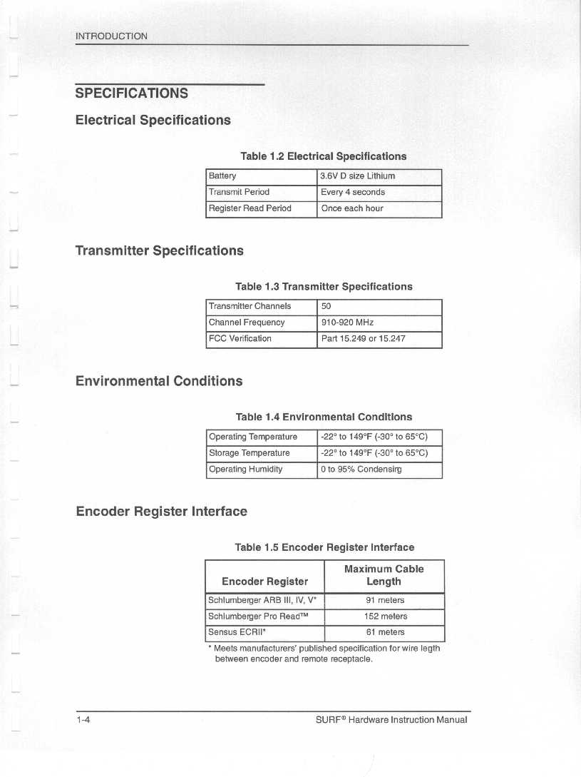
| # | Rule Parts | Frequency Range | Power Output |
|---|---|---|---|
| 1 | 15C | 911.08 MHz - 919.08 MHz | 2.50 mW |
Other Applications from Schlumberger Sema

F9CC1A-1
May 12, 2004ELECTRICITY METER WITH DUAL RF TRANSMITTERS
Equipment Class
DXX - Part 15 Low Power Communication Device Transmitter
F9CC1SA
Apr 14, 2004Electricity Meter with Dual RF Transmitters
Equipment Class
DSS - Part 15 Spread Spectrum Transmitter
F9CSMFMM-1
Nov 14, 2002Wireless LAN Radio
Equipment Class
DSS - Part 15 Spread Spectrum Transmitter
F9C26-0288
Aug 27, 2002BLT 3 LAN Transceiver
Equipment Class
DSS - Part 15 Spread Spectrum Transmitter
F9C-CBAMM
May 03, 2002Utility Meter Transmitter
Equipment Class
DSS - Part 15 Spread Spectrum Transmitter