FC3ODU7ATXAD7GHz MTX Radio
Microwave Radio Communications LLC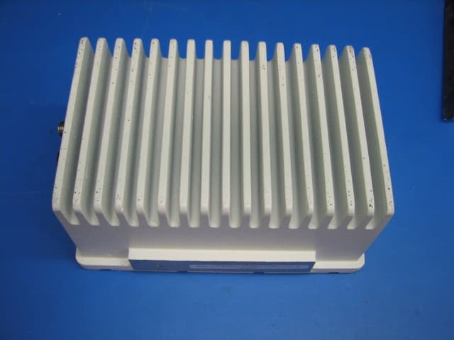
Click to zoom
Application Details
- Equipment Class
- TNB - Licensed Non-Broadcast Station Transmitter
- Date of Grant
- Dec 28, 2009
- Application Purpose
- Original Equipment
- Date of Application
- Dec 28, 2009
- Equipment Note
- 7GHz MTX Radio
- Frequency Range
- 6881.25000000 - 7118.75000000
- Country
- United States
Documents & Files
Document Text
Text extracted from the exhibit documents filed with the FCC. Open a document above to read the original.
Users Manual
MTX5000 Manual Part No. 400591-1 Rev. A June 2009 User and Technical Manual Transmitter System NOTE TO USER i MTX5000 User and Technical Manual NOTE TO USER OverviewThe MTX5000 Transmitter System (MTX5000) is a state-of-the-art transmitter system. The MTX500 0 Indoor Unit (IDU) contains a central processor used to control all functions and operations of the system. To avoid potential software hang-ups or software corruption, please read and follow the guidelines contained in the following paragraphs.Avoid Potential Operational ProblemsInformation contained in the following paragraphs identify potential problems that can be avoided by reading and following the operating procedures provided in this manual.To avoid potential operational problems, please review the information contained in the “Routine Operation” Chapter on page 3-1 . The Routine Operation Chapter contains step-by-step procedures that, when performed correctly, will eliminate potential problems that could be caused by operator error or by lack of experience with the MTX5000 system.Radio Unable to Transmit or Generally Unstable • If the radio is unable to transmit or is generally unstable, perform “Select Preset” on page 3-24 to select or re- select the proper Preset. Then verify proper transmitter operation by transmitting and receiving. • If the radio remains unstable, it may be necessary to cycle power off and on. See ”Powering the MTX5000 System” on page 3-7 to power down and power up the MTX5000. Always wait a minimum of 10 seconds between powering the radio down and then powering the radio up again. • After cycling power to off and back to on, perform “Select Preset” on page 3-24 to select the proper Preset. Then verify proper transmitter operation by transmitting and receiving. • If the radio is still unable to transmit or remains unstable, contact MRC Technical Support for assistance. Improper Power Up/Power DownIf the radio is unable to transmit, is unstable, or if the software appears to be corrupted, the Preset may have been selected or changed too soon after power was applied or the wrong Preset was selected. • Always wait a minimum of 5 seconds after the Main screen is displayed following power up before selecting a Preset. • If the wrong Preset is selected, you must wait a minimum of 5 seconds before attempting to select another Preset. Failure to wait 5 seconds minimum between Preset selections will cause software hang-ups. If the radio is unable to transmit, is unstable, or if the software appears to be corrupted, power to the radio may have been removed and reapplied too quickly. The MTX5000 central processor requires a minimum of 10 seconds to properly shutdown to avoid possible software corruption. NOTE TO USER ii MTX5000 User and Technical Manual • Software corruption can occur if the external input power to the radio was momentarily lost and was then reapplied without waiting a minimum of 10 seconds between loss of power and reapplication of input power. • The problem may also occu r if the power switch was pressed to off and back to on without waiting a minimum of 10 seconds. • To avoid problems, always wait a minimum of 10 seconds between removal or loss of power and reapplication of power to the radio. • The problem may also occur if the progress bar was displayed when power was removed from the radio. Always ensure the progress bar is not displayed on the color LCD display panel when power is removed from the radio. If this problem has occurred, press the power switch to off, wait 10 seconds minimum, and press the power switch to on. The internal processor will attempt to perform a self-recovery of the software. • During the software recovery attempt, a progress bar will be displayed on the color LCD display panel indicating the progress of the process. This progress bar will take more time to reach 100% than during a normal power up. • Do not become impatient during the software recovery process due to the time it may take for recovery. Do not remove and reapply power while the progress bar is displayed during the software self-recovery process. Software corruption will occur! • When the power up is complete and the Main screen is displayed on the color LCD display panel, verify proper transmitter operation by transmitting and receiving. • If the software is corrupted and the Main screen is not displayed, contact MRC Technical Support for assistance. Radio State IncorrectIf the radio state is incorrect, the correct Preset may not have been selected. Select the proper Preset per “Select Preset” on page 3-24 . PA Voltage Adjust Setup Software Hang-upWhen performing “Perform PA Voltage Adjust Setup” on page 3- 44 , ensure the Outdoor Unit (ODU) is properly connected to the IDU. If the ODU is not connected to the IDU and you attempt to perform this procedure, the software will hang up. • To avoid software hang-up, always ensure the ODU is connected to the IDU when performing the PA Voltage Adjust Setup procedure. • Check the Main screen ODU status indicator. If a major fault exists in the ODU, do not perform the PA Voltage Adjust Setup procedure until the fault has been corrected or until the ODU is connected to the IDU. • If the ODU is not connected to the IDU or if the ODU has suffered a failure, the PA Voltage Adjust Setup Screen will remain displayed on the color LCD display panel if the PA Voltage Adjust Setup screen Start option button is selected. If the software hangs up due to the ODU not being connected to the IDU or if the ODU has failed, perform the following: • Press the power switch to off. • Connect the ODU to the IDU or go to “Troubleshooting” on page 4-1 to correct the fault. NOTE TO USER iii MTX5000 User and Technical Manual • Press the power switch to on, perform “Select Preset” on page 3-24 to select the proper Preset. • “Perform PA Voltage Adjust Setup” on page 3-44 and then verify proper transmitter operation by transmitting and receiving. RF Levels Too HighIf the transmitted RF lev…
Text truncated - open the document above for the full version.
Users Manual
Advanced Operations 5-27 MTX5000 User and Technical Manual Figure 5-58: Alphanumeric Keypad Note When the Encryption screen is displayed in the following step and the encryption key is entered, the actual encryption key will not be displayed. 86. Enter your encryption key, select the ENT key, and observe the Encryption screen is displayed. 87. Select the Back option button and observe the Encoding screen is displayed. See Figure 5-59 . Figure 5-59: Encoding Screen - Typical 1 2 3 0 47 5 6 8 9 DEL CAN 0 ENT A D B E C F Encoding Back Service Name Network Name EBS/BISS Wayside data Service 01 Main 88. Select the Wayside data option button and observe the Wayside Data screen is displayed. See Figure 5- 60 . Figure 5-60: Wayside Data Screen - Typical 89. Select the Data Enable pull-down menu and select the Off , TTV Format , CJM2 Format , or Low Delay CJM2 option, as required. 90. Select the Baud Rate pull-down menu and select the 1200 , 2400 , 4800 , 9600 , 19200 , or 38400 option, as required. 91. Select the Submit option button. 92. Select the Back option button and observe the Encoding screen is displayed. 93. Select the Back option button and observe the MPEG screen is displayed. 94. Select the Back option button and observe the Operation Mode screen is displayed. See Figure 5- 61 on page 5-28 . Wayside Data Back Data Enable Baud Rate Off 2400 Main Advanced Operations 5-28 MTX5000 User and Technical Manual Figure 5-61: Operation Mode Screen Note When the Save As Preset screen is displayed in the following step, the Preset Text and Save text boxes will display the name and identification of the digital COFDM Preset currently being used as the digital COFDM “make-from” for this custom Preset. 95. Select the Save As Preset option button and observe the Save As Preset screen is displayed. See Figure 5-62 . Figure 5-62: Save As Preset Screen - Typical Operation Mode Back COFDM FMT ASI IP SCM LMS-T Save As Preset DVBS MPEG Main Save As Preset Back Preset Text Digital – COFDM QPSK4:2:0,8,1/2,comp Save C Main Notes In the following steps, if a factory default digital COFDM Preset was used as a “make-from” to prepare this custom Preset, the Preset Text text box and the Save text box must be changed. You cannot change or overwrite any factory default Presets! If a custom digital COFDM Preset was used as a “make-from” to prepare this custom Preset, a brief description of the custom Preset must be entered in the Preset Text text box for easy identification purposes. 96. Select the Preset Text option button and observe that the keyboard screen is displayed. See Figure 5-63 . Figure 5-63: Keyboard Screen 97. Enter a unique digital COFDM Preset description, as required, and select the Enter key. 98. Observe the Save As Preset screen is displayed and the Preset Text text box displays the Preset description. ! @ # $ % ^ & * ( ) _ + Q W E R T Y U I O P { } A S D F G H J K L : Z X C V B N M < > ? Shift BS Clear Cancel Enter “ Advanced Operations 5-29 MTX5000 User and Technical Manual Notes When saving the new custom digital Preset in the following step, the Preset number will automatically be increased to the next available Preset number to avoid overwriting an existing Preset. If you wish to overwrite the existing Preset number (unless it is a factory default Preset), enter the Preset number to be overwritten. A warning message will be displayed asking “ Are you sure? ”. Select the Yes option button. Once an existing custom Preset is overwritten, it cannot be recovered. It must be re-entered from scratch. 99. Select the Save option button and observe the numeric keypad is displayed. See Figure 5-64 . Figure 5-64: Numeric Keypad - Typical Notes When saving Presets in the following steps, Preset A thru Preset J are factory default Presets. The factory default Preset numbers cannot be changed. 1 2 3 47 5 6 8 9 CLR 0 ESC ENT Next Available Preset Number Notes To change the default Preset number, perform step 100 and go to step 101 . To accept the next available Preset number, go to step 101 100. Select the CLR key and enter the Preset number required. 101. Select the ENT key and observe the Are you sure? confirmation screen is displayed. See Figure 5-65 . Figure 5-65: Confirmation Screen 102. Select the YES option button and observe the Please Wait! message box is displayed. See Figure 5-66 . Figure 5-66: Please Wait Message Box 103. After a short delay, observe the Save As Preset screen is displayed. No Are you sure?Yes No Please Wait! Yes Advanced Operations 5-30 MTX5000 User and Technical Manual 104. Select the Main option button and observe the Main screen is displayed. 5.4.3 Create or Update Digital ASI Preset Configuration Settings in Local ModeThe procedure required to create a new custom digital ASI Preset configuration or to update an existing digital ASI Preset configuration is contained in the following steps.When preparing a new digital ASI Preset, you must first select an existing digital ASI Preset from either the ASI factory default Preset or from your own custom digital ASI Presets. The selected digital ASI Preset will be used as a “make-from” to prepare the new digital ASI Preset configuration.Please note that while the ASI factory default Preset may be used to prepare a new Preset configuration, the factory default Preset cannot be changed or deleted . It can only be used as a “make-from”. When the new configuration is prepared using the factory default Preset, it cannot be saved with the factory Preset number or Preset name. A new Preset number and Preset name must be assigned to the new Preset.When using a custom Preset as a “make-from”, the new Preset should be saved with a new Preset number. When you save the new Preset, the Preset number will automatically be increased to the next available Preset number. If you select an existing Preset number when saving the new Preset, the original custom Preset will be overwritten and cannot be recovered. The only way to restore a Preset that has be…
Text truncated - open the document above for the full version.
Cover Letter(s)
July 20, 2009 T0: Federal Communications Commission 7435 Oakland Mills Road Columbia, MD 21046-1609 Microwave Radio Communications 101 Billerica Ave, Bldg 6 N. Billerica, MA 01862 Re: Confidentiality Request This letter is to comply with 47 CFR 0.457 (d) (2) pertaining to confidential material. Microwave Radio Communications requests that the following documents regarding this submission for FCC ID FC3ODU7ATXAD be kept confidential: 1. Schematics 2. Block Diagrams 3. Circuit/Technical Description 4. Parts List 5. Testing/Tune Up Procedure The material above contains technical data which would customarily be guarded from competitors. Sincerely, Sal Blatti Manager, R&D System Qualification and Compliance Microwave Radio Communications 101 Billerica Ave., Bldg. 6 N. Billerica, MA 01862-1256 Tel: (978) 671-5700 Fax: (978) 671-5800
Cover Letter(s)
oetech oetechoetech oetech @ @@ @fccsun fccsunfccsun fccsun 27 2727 27w ww w. .. .fcc fccfcc fcc . .. .gov govgov gov 09/21/2009 11:40 AM To Yunus Faziloglu/USA/VERITAS@VERITAS cc bcc Subject Response to Inquiry to FCC (Tracking Number 835092) (TCB) Ref FCC Home | Search | Updates | E-Filing | Initiatives | For Consumers | Find People Office of Engineering and Technology Inquiry: Dear Sir/Madam, We would like to have your guidance for a certification we are about to perform. Please see attached "Rule parts availability question.pdf" for the detailed question and "User Manual Part 1.pdf" document for additional information. Your clarification will be greatly appreciated. Please let us know if you require further information. Yunus Faziloglu, TCB Manager, Curtis-Straus LLC. Response: This device can be certified under multiple rule parts if it meets the rules for each rule specified in the application. Rule parts availability question User Manual Part 1 Do not reply to this message. Please select the Reply to an Inquiry Response link from the OET Inquiry System to add any additional information pertaining to this inquiry.
RF Exposure Info
Notices Notices-ii MTX5000 User and Technical Manual Changes or modifications not ex pressly approved by MRC could void the user’s authority to operate the equipment.General Safety InformationThe following safety requiremen ts, as well as local site requirements and regulations, must be observed by personnel operating and maintaining the equipment covered by this manual to ensure awareness of potential hazards.WARNING - RF Power HazardHigh levels of RF power are present in the unit. Exposure to RF or microwave power can cause burns and may be harmful to health.Remove power from the unit before disconnecting any RF cables and before inspecting damaged cables and/or antennas.Avoid standing in front of high gain antennas (such as a dish antenna) and never look into the open end of a waveguide or cable where RF power may be present.RF Exposure - Safe Working DistancesMRC provides this warning for safety purposes with the intent to inform the user of the potential hazard to RF exposure. The following guidelines for safe op eration were derived from OET bulletin 65, August 1997, as recommended by the Federal Communications Commission (FCC).The MTX5000 Transmitter System is a mobile transmitter system designed to provide serv ices to broadcast ENG users under CFR 74 subpart F and 74.601 TV pickup stations. This unit, operated without an antenna, will not create RF energy exceeding 1.0 mW/cm 2 , the FCC limit for exposure. Once connected to an antenna, the potential for harmful exposure will be greatly enhanced.In this situation, a certain distance from the radiator is to be maintained. Calculations need to be performed to understand what that safe margin for exposure is. This is known as the Maximum Permissible Exposure (MPE) limit. Note Hazardous RF radiation limits and recommended distances may vary by country. Ensure that all applicable state and federal regulations are observed when using this transmitter. Calculations provided are for common antennas often utilized in the ENG environment. The following formula used is that suggested by OET 65.Calculating MPEEIRP = P * (10 ^ (G / 10)) = (antilog of G/10) * PP = RF power delivered to the antenna in mWG = Power gain of the antenna in the direction of interest relative to an isotropic radiatorR = distance to the center of radiation of the antenna in centimetersS = MPE in mW/cm² (milliwatts per square centimeters)ConversionsdBi to numeric gain = Antilog (dBi/10)Feet to centimeters = Feet * 30.48Centimeters to Feet = cm * .03284 π = 12.57 Notices Notices-iii MTX5000 User and Technical Manual User InputRF power delivered to the antenna = WattsAntenna gain (referenced to isotropic antenna) = dBiDistance from the center of radiation = FeetCalculation steps: 1. [P] RF power input. Convert watts to milliwatts = Watts * 1000 2. [G] Antenna gain dBi. Convert to numeric gain = Antilog (dBi/10) 3. [EIRP] Multiply P * G 4. [R] Convert centimeters to feet = Centimeters * .03285. Square R6. Multiply R² * 4 π 7. [S] Divide (R² * 4 π ) into EIRP S = Power Density in milliwatts per square centimeters. Note: At frequencies above 1500 MHz, S must not be greater than 1.ReferenceFCC OET Bulletin 65, August 1997 - Evaluating Compliance with FCC Guidelines for Human Exposure to Radio Frequency Electromagnetic FieldsThe examples shown in Figure 1 and Figure 2 are typical graphs for an MRC STRATA Transmitter and show the permissible exposure distance for various antennas. Graphs and data will vary, based on the actual transmitter, output power, frequency, and antenna utilized. One plot provides the permissible output of the transmitter for digital modulation, and the other plot for analog modulation. MRC, in accordance with the requirements set forth by the FCC, provides this information as a guide to the user. It is assumed that the users of this equipment are licensed and qualified to operate the equipment per the guidelines and recommendations contained within the product user guides and in accordance with any FCC rules that may apply.Figure 1 with its corresponding table shows the 2GHz MPE.Figure 1: MTX5000 MPE 2GHz Antenna Gain (dBi) Minimum Dis - tance from Antenna (cm) Minimum Distance from Antenna (inch) 0 28 11.02 5 50 19.68 16 177 69.67 20 279 109.81 35 1569 617.56 Notices Notices-iv MTX5000 User and Technical Manual Figure 2 with its corresponding table shows the 7GHz MPE.Figure 2: MTX5000 MPE 7GHz Antenna Gain (dBi) Minimum Dis - tance from Antenna (cm) Minimum Distance from Antenna (inch) 0 26 10.23 5 46 18.11 16 163 64.16 20 258 101.55 35 1448 569.93 Conventions Pay special attention to information marked in one of the following ways: WARNING Follow WARNINGS closely to prevent personal injury or death . CAUTION Follow CAUTIONS to prevent damage to the equipment. Note Notes provide additional information to assist you in using and maintaining the equipment.
Test Report
Curtis-Straus LLC is accredited to ISO/IEC 17025 by A2LA for the specific scope of accreditation under Certificate Number 1627-01. This report may contain data which is not covered by the A2LA accreditation. Any opinions or interpretations expressed in this report are outside the scope of our A2LA accreditation as A2LA only accredits testing. ____________________________________________________________ Curtis-Straus • •• • 527 Great Road • •• • Littleton, MA • •• • TEL (978) 486-8880 • •• • FAX (978) 486-8828 page 1 of 41 Test Report Report No EJ0250-1 Issue 2 Client Microwave Radio Communications LLC 101 Billerica Ave, Building 6 North Billerica, MA 01862 Phone 978-671-5778 FRN 0004267712 System Models 908347-03, 907033-03, 908725-03 FCC ID FC3ODU2ATXADH FC3ODU7ATXAD Equipment Type Equipment Code Licensed Non-Broadcast Station Transmitter TNB Results As detailed within this report Prepared by Evan Gould – Compliance Engineer Authorized by Mairaj Hussein – EMC Manager Issue Date June 11, 2009 Conditions of Issue This Test Report is issued subject to the conditions stated in the ‘Conditions of Testing’ section on page 40 of this report. Test Report for Microwave Radio Communications LLC • •• • Report No. EJ0250-1 Issue 2 June 11, 2009 ______________________________________________________________________ ____________________________________________________________ Curtis-Straus • •• • 527 Great Road • •• • Littleton, MA • •• • TEL (978) 486-8880 • •• • FAX (978) 486-8828 page 2 of 41 Contents Summary.................................................................................................................................3 Test Methodology ....................................................................................................................4 Product Tested - Configuration Documentation .......................................................................5 Band Edges.............................................................................................................................6 Output Power ..........................................................................................................................9 Emission Masks – Digital Modulation ....................................................................................10 Emission Masks – Analog Modulation ...................................................................................22 Out-of-Band Emissions – Conducted.....................................................................................29 Out-of-Band Emissions – Radiated........................................................................................31 Frequency Tolerance.............................................................................................................32 Measurement Uncertainty......................................................................................................33 Test Equipment Used ............................................................................................................34 Conditions Of Testing ............................................................................................................40 Test Report for Microwave Radio Communications LLC • •• • Report No. EJ0250-1 Issue 2 June 11, 2009 ______________________________________________________________________ _____________________________________________________________ Curtis-Straus • •• • 527 Great Road • •• • Littleton, MA • •• • TEL (978) 486-8880 • •• • FAX (978) 486-8828 page 3 of 41 Summary The purpose of this report is to support two applications for Certification of licensed devices operating pursuant to Parts 74, 78, and 101. The products are the Microwave Radio 2GHz & 7GHz MTX Radios. Under Part 74, these devices operate as mobile TV Pickup Stations [74.601(a)] within the frequency bands: 2025-2110, 2450-2483.5, 6875-7125, and 6425- 6525MHz. The applicability of Rule Parts to Frequency Bands is shown in the following table: Frequency BandRule Parts 2025-2110MHz74, 78 2450-2483.574 6425-652574, 78, 101 6875-712574, 78 Each product consists of an RF head in combination with the baseband unit. Only one combination can be active at a time, and the FCC ID’s will be placed on their respective RF head units. This report contains measurements supporting both Certification applications. A simple block diagram of the product is shown below for clarification. Baseband Unit 2GHz RF Head 7GHz RF Head The channel plans are shown below: 2GHz Band ChannelOffset -CenterOffset + 12028.52031.52034.5 22040.52043.52046.5 32052.52055.52058.5 42064.52067.52070.5 52076.52079.52082.5 62088.52091.52094.5 72100.52103.52106.5 82454.252458.52462.75 924712475.252479.5 102487.52491.752496 Test Report for Microwave Radio Communications LLC • •• • Report No. EJ0250-1 Issue 2 June 11, 2009 ______________________________________________________________________ _____________________________________________________________ Curtis-Straus • •• • 527 Great Road • •• • Littleton, MA • •• • TEL (978) 486-8880 • •• • FAX (978) 486-8828 page 4 of 41 7GHz Band ChannelOffset -CenterOffset + 16881.256887.56893.75 26906.256912.56918.75 36931.256937.56943.75 46956.256962.56968.75 56981.256987.56993.75 67006.257012.57018.75 77031.257037.57043.75 87056.257062.57068.75 97081.257087.57093.75 107106.257112.57118.75 116431.256437.56443.75 126456.256462.56468.75 136481.256487.56493.75 146506.256512.56518.75 As can be seen in the Band Edges section of this report, the channels which are grayed out in the above tables are channel settings which are not allowed to be used as they produce fundamental emissions which lie outside the bands of operation. Test Methodology Testing was performed according to ANSI/TIA-603-C-2004. Frequency range investigated: 30MHz – 75GHz Testing was performed with the following modulations: Digital: COFDM QPSK 8MHz FE1/2 GI 1/8 Analog: FM Test Report for Microwave Radio Communications LLC • •• • Report No. EJ0250-…
Text truncated - open the document above for the full version.
Contact Information
Applicant
Richard Miller(Lead Solutions Engineer)
Test Firm
BUREAU VERITAS CONSUMER PRODUCTS SERVICES, INC.Ozgur Ozturk
[email protected]978-486-8880
Technical Specifications
| # | Rule Parts | Frequency Range | Power Output | Emission | Tolerance |
|---|---|---|---|---|---|
| 5 | 74 | 6.88 GHz - 7.12 GHz | 8.32 W | 25M0F8W | 1000 Hz |
Other Applications from Microwave Radio Communications LLC
FC3NST2G7G
Nov 09, 2015Microwave Mobile Transmitter
Equipment Class
TNB - Licensed Non-Broadcast Station Transmitter
FC3L32112GAMP
Mar 09, 2014Booster Amp
Equipment Class
AMP - Amplifier
FC3HDX2025D
Jun 04, 2013Microwave Downlink transmitter
Equipment Class
TNB - Licensed Non-Broadcast Station Transmitter
FC3HDX064D
Sep 11, 2011Microwave Downlink Transmitter
Equipment Class
TNB - Licensed Non-Broadcast Station Transmitter
FC3PTX270AD
Aug 03, 2011PTX-PRO Transmitter
Equipment Class
TNB - Licensed Non-Broadcast Station Transmitter