FC3PTX270ADPTX-PRO Transmitter
Microwave Radio Communications LLC
Click to zoom
Application Details
- Equipment Class
- TNB - Licensed Non-Broadcast Station Transmitter
- Date of Grant
- Aug 03, 2011
- Application Purpose
- Original Equipment
- Date of Application
- Aug 03, 2011
- Equipment Note
- PTX-PRO Transmitter
- Frequency Range
- 6881.25000000 - 7118.75000000
- Country
- United States
Documents & Files
Document Text
Text extracted from the exhibit documents filed with the FCC. Open a document above to read the original.
Users Manual
User and Technical PTX-PRO Transmitter Manual Part No. 400611-1 Rev. C July 2011 Copyright © 2011 Part number 400611-1 Printed in U.S.A. Authorized EU representative: Vislink PLC Quality Certification Vislink is certified to ISO 9001:2008. The Vislink trademark and other trademarks are registered trademarks in the United States and/or other countries. Microsoft®, Windows®, and Internet Explorer® are registered trademarks of Microsoft Corporation in the United States and/or other countries. Proprietary Material The information and design contained within this manual was originated by and is the property of Vislink. Vislink reserves all patent proprietary design, manufacturing, reproduction use, and sales rights thereto, and to any articles disclosed therein, except to the extent rights are expressly granted to others. The foregoing does not apply to vendor proprietary parts. Vislink has made every effort to ensure the accuracy of the material contained in this manual at the time of printing. As specifications, equipment, and this manual are subject to change without notice, Vislink assumes no responsibility or liability whatsoever for any errors or inaccuracies that may appear in this manual or for any decisions based on its use. This manual is supplied for information purposes only and should not be construed as a commitment by Vislink. The information in this manual remains the property of Vislink and may not be used, disclosed, or reproduced in any form whatsoever, without the prior written consent of Vislink. Vislink reserves the right to make changes to equipment and specifications of the product described in this manual at any time without notice and without obligation to notify any person of such changes. General Safety Information The following safety requirements, as well as local site requirements and regulations, must be observed by personnel operating and maintaining the equipment covered by this manual to ensure awareness of potential hazards. This equipment has been tested and found to comply with the limits for a Class A digital device, pursuant to Part 15 of the FCC Rules. These limits are designed to provide reasonable protection against harmful interference when the equipment is operated in a commercial environment. This equipment generates, uses, and can radiate radio frequency energy. If not installed and used in accordance with the instruction manual, it may cause harmful interference to radio communications. Operation of this equipment in a residential area is likely to cause harmful interference in which case the user will be required to correct the interference at his own expense. About this Manual This manual is intended for use by qualified operators, installers, and service personnel. Users of this manual should already be familiar with basic concepts of radio, video, and audio. For information about terms in this manual, see Glossary of Terms and Abbreviations (Part No. 400576-1). Pay special attention to Notes, Cautions, and Warnings. Read Notes for important information to assist you in using and maintaining the equipment. Follow CAUTIONS to prevent damage to the equipment. Follow WARNINGS to prevent personal injury or death. Symbols The following symbols may be on the equipment or in this manual: WARNING: General Warning. Risk of Danger. Frame or Chassis Ground: Identifies the frame or chassis terminal. WARNING: Risk of Electric Shock.Earth Ground: Identifies the earth ground terminal. CAUTION: Electrostatic Discharge. Possible Damage to Equipment.Fuse (either icon): Identifies fuses or their location. Protective Earth Ground: Identifies any terminal intended for connection to an external conductor for protection against elec- tric shock in case of a fault, or the terminal on a protective earth electrode. Waste Electrical and Electronic Equipment (WEEE): The product must not be disposed of with other waste. You must dispose of the waste equipment by handing it over to a desig- nated collection point for recycling. 101 Billerica Avenue - Bldg. 6 North Billerica, MA 01862-1256 USA TEL: 800.490.5700 or +1.978.671.5700 Contents-1PTX-PRO User and Technical Manual Contents 1 About the PTX-PRO 1.1 Front Panel Controls, Indicators, and Connectors - - - - - - - - - - - - - - - - - - - 1-2 1.2 Rear Panel Connectors and Fuses - - - - - - - - - - - - - - - - - - - - - - - - - - - - - - 1-3 1.3 Related Documents- - - - - - - - - - - - - - - - - - - - - - - - - - - - - - - - - - - - - - - - - 1-4 1.4 Channel Plans (2, 7, and 13) - - - - - - - - - - - - - - - - - - - - - - - - - - - - - - - - - - 1-5 1.4.1 The 2 GHz Channel Plan - - - - - - - - - - - - - - - - - - - - - - - - - - - - - - - - - 1-5 1.4.2 The 7 GHz Channel Plan - - - - - - - - - - - - - - - - - - - - - - - - - - - - - - - - - 1-5 1.4.3 The 13 GHz Channel Plan - - - - - - - - - - - - - - - - - - - - - - - - - - - - - - - - 1-6 2 Installing the PTX-PRO 2.1 Unpacking the PTX-PRO - - - - - - - - - - - - - - - - - - - - - - - - - - - - - - - - - - - - - 2-1 2.2 Preparing to Install the PTX-PRO - - - - - - - - - - - - - - - - - - - - - - - - - - - - - - - 2-1 2.2.1 Operating in Safety - - - - - - - - - - - - - - - - - - - - - - - - - - - - - - - - - - - - - 2-1 2.2.2 Powering and Grounding the PTX-PRO- - - - - - - - - - - - - - - - - - - - - - - 2-4 2.3 Mounting on an MRC Tripod - - - - - - - - - - - - - - - - - - - - - - - - - - - - - - - - - - 2-5 2.4 Mounting on a Non-MRC Tripod - - - - - - - - - - - - - - - - - - - - - - - - - - - - - - - - 2-5 2.5 Installing Configurator Software - - - - - - - - - - - - - - - - - - - - - - - - - - - - - - - - 2-8 3 Operating the PTX-PRO 3.1 Powering Up- - - - - - - - - - - - - - - - - - - - - - - - - - - - - - - - - - - - - - - - - - - - - - 3-1 3.2 Using the Display Screen- - - - - - - - - - - - - - - - - - - - - - - - - - - - - - - - - - - - - 3-1 3.3 Monitoring PTX-PRO Operations - - - - - - - - - - - - - - - - - - - - - - - - - - - - - - - 3-2 3.4 Configuring the PTX-PRO …
Text truncated - open the document above for the full version.
External Photos
EJ1631-1 Microwave Radio Communications External Photographs Transmit Unit EJ1631-1 Microwave Radio Communications External Photographs EJ1631-1 Microwave Radio Communications External Photographs EJ1631-1 Microwave Radio Communications External Photographs Receive Unit EJ1631-1 Microwave Radio Communications External Photographs EJ1631-1 Microwave Radio Communications External Photographs
Internal Photos
TRANSMITTER PHOTOS PTXPRO 2 / 7GHz MOBILE (FC3PTX270AD) MRC PART NUMBER (908370-01) INSIDE TOP VIEW AC Power supply Power AMP RF / IF Module RF Upconverter INSIDE BOTTOM VIEW MPEG-2 Encoder / COFDM Modulator Baseband Combiner DC Power Supply FM Modulator FRONT EXTERNAL VIEW AUDIO INPUT CONNECTION FREQUENCY OFFSET AND CHANNEL CONTROL POWER IN ON / OFF SWITCH, INPUT CONNECTIONS REAR EXTERNAL VIEW DIGITAL AUDIO I/P RF OUTPUT TO ANTENNA AC / DC FUSES DATA COMM PORT Label Info
RF Exposure Info
2-2 Installing the PTX-PROPTX-PRO User and Technical Manual WARNING - RF Power Hazard WARNING The unit has high levels of RF power. Exposure to RF or microwave power can cause burns and may be harmful to health. •Remove power from the unit before disconnecting any RF cables and before inspecting damaged cables and/or antennas. •Avoid standing in front of high gain antennas (such as a dish antenna) and never look into the open end of a waveguide or cable where RF power may be present. The following guidelines for safe operation were derived from OET bulletin 65, August 1997, as recommended by the Federal Communications Commission (FCC). The PTX-PRO was designed to provide services to broadcast ENG users under CFR 74 subpart F and 74.601 TV pickup stations. This unit, operated without an antenna, will not create RF energy exceeding 1.0 mW/cm 2 , the FCC limit for exposure. Once connected to an antenna, the potential for harmful exposure will be greatly enhanced. In this situation, a certain distance from the radiator is to be maintained. Calculations need to be performed to understand what that safe margin for exposure is. This is known as the Maximum Permissible Exposure (MPE) limit. Calculations provided are for common antennas often utilized in the ENG environment. The following formula used is that suggested by OET 65. Calculating MPE EIRP = P * (10 ^ (G / 10)) = (antilog of G/10) * P P = RF power delivered to the antenna in mW G = Power gain of the antenna in the direction of interest relative to an isotropic radiator R = distance to the center of radiation of the antenna in centimeters S = MPE in mW/cm² (milliwatts per square centimeters) Conversions dBi to numeric gain = Antilog (dBi/10) Feet to centimeters = Feet * 30.48 Centimeters to Feet = cm * .0328 4 π = 12.57 User Input RF power delivered to the antenna = Watts Antenna gain (referenced to isotropic antenna) = dBi Distance from the center of radiation = Feet Installing the PTX-PRO 2-3PTX-PRO User and Technical Manual Calculation steps: 1. [P] RF power input. Watts to milliwatts = Watts * 1000 2. [G] Antenna gain dBi. Numeric gain = Antilog (dBi/10) 3. [EIRP] Multiply P * G 4. [R] Centimeters to feet = Centimeters * .0328 5. Square R 6. Multiply R² * 4π 7. [S] Divide (R² * 4π) into EIRP S = Power Density in milliwatts per square centimeters. Note At frequencies above 1500 MHz, S must not be greater than 1. Reference FCC OET Bulletin 65, August 1997 - Evaluating Compliance with FCC Guidelines for Human Exposure to Radio Frequency Electromagnetic Fields The following graph and associated table show the permissible exposure distance for various antennas. Graphs and data will vary, based on the actual transmitter, output power, frequency, and antenna utilized. One plot provides the permissible output of the transmitter for digital modulation, and the other plot for analog modulation. This information is provided, in accordance with the requirements set forth by the FCC, as a guide for you assuming that users of this equipment are licensed and qualified to operate the equipment per the guidelines and recommendations contained within the product user guides and in accordance with any FCC rules that may apply. 2-4 Installing the PTX-PROPTX-PRO User and Technical Manual 2.2.2Powering and Grounding the PTX-PRO For safe operation, all equipment must be properly grounded. •Connect the unit to a common (vehicle or aircraft) ground. •Make the ground wire as short and straight as possible. CAUTION Be sure the equipment grounding follows applicable electrical codes. Never modify a grounded power plug to connect to an ungrounded receptacle. Ensure that the power being supplied matches the power required by the equipment. You can find power ratings for equipment on a rating plate, usually on the rear panel. Ensure that the electrical supply is protected by over-current protection devices as required by the applicable electrical codes. If necessary, consult a licensed electrician. Antenna Gain (dBi) Minimum Safe Distance from Antenna (cm) Minimum Safe Distance from Antenna (inch) 0207.9 53212.6 1611344.5 2017870.1 351001394.1
Test Setup Photos
EJ1631-1 Microwave Radio Communications Test Setup Photographs Conducted measurements under extreme conditions Conductive measurements EJ1631-1 Microwave Radio Communications Test Setup Photographs Radiated emission measurements below 1GHz - Rear EJ1631-1 Microwave Radio Communications Test Setup Photographs Radiated emission measurements below 1GHz - Front EJ1631-1 Microwave Radio Communications Test Setup Photographs Radiated emission measurements above 1GHz - Front Radiated emission measurements above 1GHz - Rear EJ1631-1 Microwave Radio Communications Test Setup Photographs Radiated emission measurements above 18GHz
Contact Information
Applicant
Richard Miller(Lead Solutions Engineer)
Test Firm
Curtis-Straus LLC.Jonathan Stewart
[email protected]9784868880
Technical Specifications
| # | Rule Parts | Frequency Range | Power Output | Emission | Tolerance |
|---|---|---|---|---|---|
| 8 | 74 | 6.88 GHz - 7.12 GHz | 3.981 W | 25M0F8W | 5 ppm |
Other Applications from Microwave Radio Communications LLC
FC3NST2G7G
Nov 09, 2015Microwave Mobile Transmitter
Equipment Class
TNB - Licensed Non-Broadcast Station Transmitter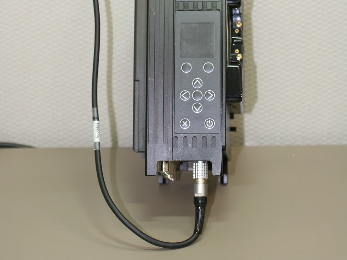
FC3L32112GAMP
Mar 09, 2014Booster Amp
Equipment Class
AMP - Amplifier
FC3HDX2025D
Jun 04, 2013Microwave Downlink transmitter
Equipment Class
TNB - Licensed Non-Broadcast Station Transmitter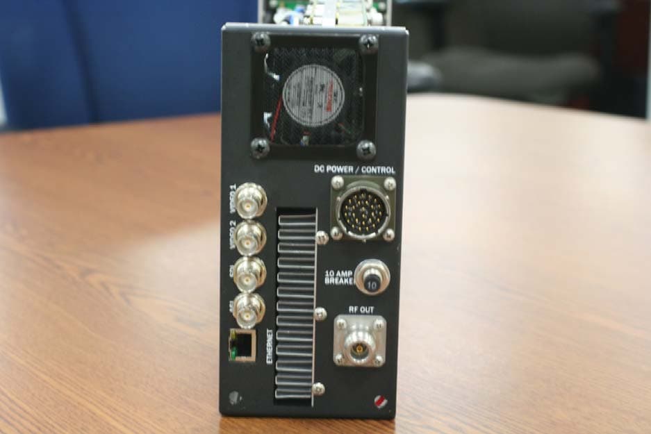
FC3HDX064D
Sep 11, 2011Microwave Downlink Transmitter
Equipment Class
TNB - Licensed Non-Broadcast Station Transmitter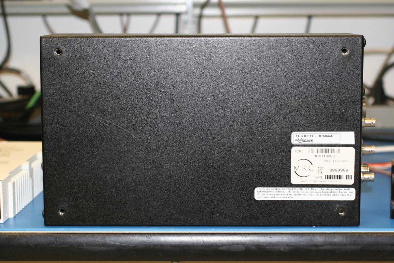
FC3HDX044D
May 23, 2011Microwave Downlink Transmitter
Equipment Class
TNB - Licensed Non-Broadcast Station Transmitter