FC3STAHPU2DSTRATA Amplifier
Microwave Radio Communications LLC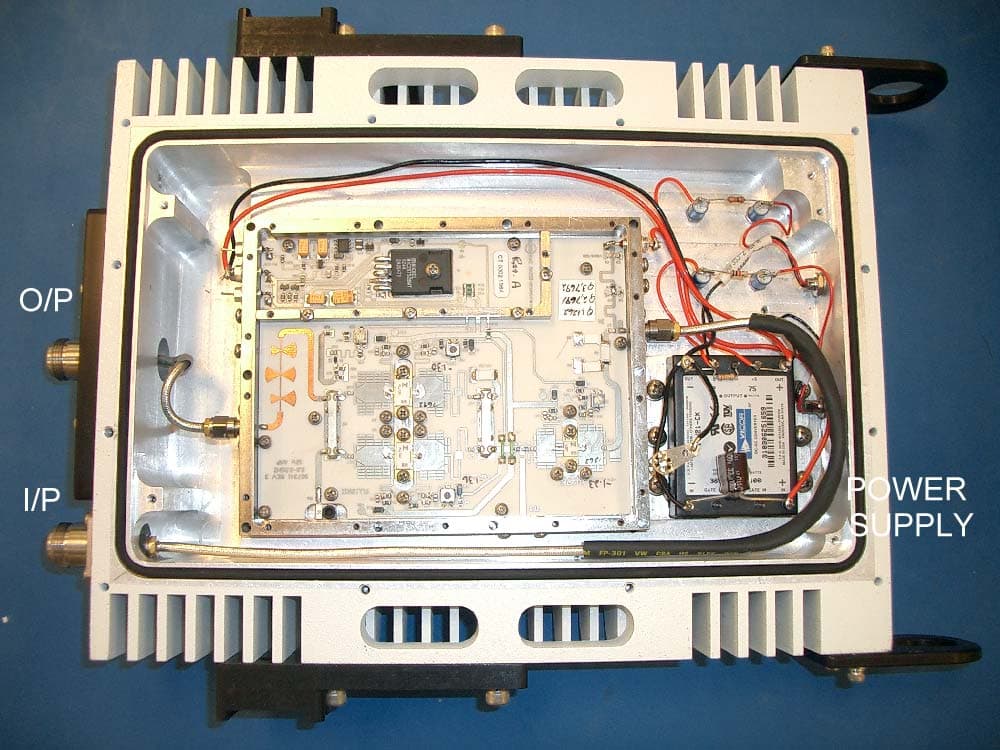
Click to zoom
Application Details
- Equipment Class
- AMP - Amplifier
- Date of Grant
- Dec 17, 2003
- Application Purpose
- Original Equipment
- Date of Application
- Dec 17, 2003
- Equipment Note
- STRATA Amplifier
- Frequency Range
- 1990.00000000 - 2700.00000000
- Country
- United States
Documents & Files
Document Text
Text extracted from the exhibit documents filed with the FCC. Open a document above to read the original.
Users Manual
Strata Operations Guide - 1 - Strata Transmitter Operations Guide Revision 3.0 May 2003 Microwave Radio Communications 101 Billerica Avenue, Bldg 6 (978) 671-5700 N. Billerica, MA 01862-1256 www.mrcbroadcast.com Strata Operations Guide - 2 - Introduction The Microwave Radio Communications (MRC) Strata system provides a reliable and highly flexible video microwave transport system. This operations guide provides basic system operations information and details for hands-on operation of this equipment. System Description Figure 1 below shows the overall Strata system architecture for a fully equipped system. TCUTXUHPU !NTSC !PAL !SDI !ASI !IF RF OUT RF/DC TelemetryTelemetry IF or Baseband Signal DC Simplex Powering IN Dummy Load 12 v to 48 v DC RS-232 1.84 MHz OOK Tone 12 v to 48 v DC RS-232 Figure 1 – Strata Transmitter System Architecture The primary system features are: oLightweight, Modular, Multi-Unit Design oAnalog, Digital, or Analog/Digital Switchable oMPEG Encoding (4:2:0, 4:2:2) oCOFDM Modulation with Selectable Guard Interval oDigital Modulation for QPSK, 16QAM, and 64QAM oNTSC or PAL Modulation with Audio (4 mono or 2 stereo) oTripod, Half Rack, or Full Rack Mounts oFront Panel Remote Controlled oBands from 2 to 15 GHz oWide Choice of Antennas Note that the TCU (Transmitter Control Unit) and the TXU (Transmitter Unit) may be operated in a stand-alone configuration depending on specific video transport applications. TCU Description The TCU component can accept a wide variety of signal formats and provide several different output signal formats. Figure 2 below shows the basic functions of the TCU. Strata Operations Guide - 3 - MPEG COFDM FMT COAX IN COFDM 70 MHZ MONITOR COAX OUT SDI ASI FMT CV Filter !NTSC !PAL !SDI !ASI !IF MPEG CV Telemetry ASI 70 MHz IF Bypass Note: Either or both MPEG/COFDM or FMT boards may be installed !COFDM !IF CV !IF !ASI IF CV ASI Only Mode Figure 2 - Strata TCU Functional Diagram Note: The TCU may be supplied with or without the MPEG/COFDM or FMT options. TXU Description Like the TCU component, the TXU can accept a wide variety of signal formats but includes an RF up- converter for use in transporting signals over a microwave radio link. Figure 3 below shows the basic functions of the TXU. MPEG COFDM FMT SIGNAL IN ASI MON ASI COFDM 70 MHZ 70 MHZ RF OUT SDI MPEG MPEG CV ASI Input FMT CV !NTSC !PAL !SDI !ASI !IF Filter Telemetry SDI/ASI IF CV IF/RF Up Converter/Amplifier 70 MHz Figure 3 – Strata TXU Functional Diagram Note: The TXU may be supplied with or without the MPEG/COFDM or FMT options. Strata Operations Guide - 4 - HPU Description For those applications requiring a higher RF output level, the HPU (High Power Unit) may be used to boost the signal level to between 2 and 12 watts of microwave output power depending on the modulation format used. Figure 4 below shows the functional architecture of the HPU device. HPURF INRF OUT Figure 4 – HPU Functional Diagram Theory of Operation The Strata TX system is comprised of the following primary components: • Command and Control Power Supply module • Combiner Circuit • MPEG encoder/COFDM modulator module (digital mode) • FMT (FM Transmitter) (analog mode) • IF/RF Unit • HPU (High Power Unit) Note that some or all of these components may be included in a fully functional Strata TX system depending on specific customer applications, e.g., switchable analog and digital transmitting system, etc. Where switchable analog and digital video transmission is required, the Strata TX system installs the digital and analog video modulator modules and the IF/RF module in separate housings. In this case a TCU (Transmitter Control Unit) houses the MPEG/COFDM, FMT and Combiner circuits with the IF/RF unit installed in a separate TXU (Transmitter Unit) housing. This arrangement also allows the video modulation components (TCU) to be physically separated from the IF/RF up-converter by up to 600 feet. Command and Control Power Supply The TCU and TXU Command and Control/Power Supply modules contain external and internal communications circuitry as well as supplying the necessary system voltages. The power supply portion accepts a wide range DC input voltage (+10.5 to +48 volts) and distributes appropriate output voltages to the various circuits. The command and control circuits handle inter-module communications and provide external RS-232 communications to external peripheral equipment, such as a remote control device (helicopter operation) or to a PC capable of running Windows based configuration software. An on-board microprocessor manages the system configuration and operation of all modules to which it is connected, i.e., MPEG/COFDM, FMT, IF/RF modules, etc. In addition, for those applications that employ both TCU and TXU housings, a communications link superimposed over the inter-connecting IF coaxial cable provides communications to all system modules. This ensures the TCU and TXU may control each other’s operation, i.e., permit switching modes of operation, change system presets, etc. Strata Operations Guide - 5 - Therefore, where both a TCU and TXU are used, total system control may be accomplished using front panel or remote control from either housing. MPEG/COFDM Encoder/Modulator This is the heart of the Strata TX digital mode circuitry. This versatile circuit may be configured to accept a wide range of digital or analog video and audio signal inputs and provide COFDM (70 MHz), IF (70 MHz) or ASI video signal outputs. When installed in a TCU housing, the various signal inputs and outputs are connected through the TCU Combiner circuit where the various signal inputs and outputs are switched using software controls. FMT The optional FMT module accepts standard NTSC or PAL analog video and audio signals and FM modulates these signals on a 70 MHz carrier. Using the MRC supplied configuration software, four different audio sub-carrier frequencies may be defined in which up to four standard audio signals may be transported…
Text truncated - open the document above for the full version.
Block Diagram
DC BA 4321 DC BA 4321 907340 STRATA HPU PA BLOCK DIA SIZE FSCM NO DWG NO REV SCALE 1 : 1 SHEET 1 OF 1 REGULATOR LPF Q2 Q1 ATTEN ATTEN Q1 IN OUT
Cover Letter(s)
Response to TCB Findings 1. In parts of the user manual and operational description the amplifier power rated value is shown as 12W. Please clarify. The amplifier in general is rated for 12W, but in application field it will be usewd in the range of 5W maximum power to maintain linearity and that is what we are applying for. 2. Can the amplifier transmit on multiple channels simultaneously for conducted spurious emissions intermodulation concerns. No it can not.
External Photos
STRATA POWER AMPLIFIER EXTERIOR FRONT VIEW STAHPU2D STRATA POWER AMPLIFIER EXTERIOR REAR VIEW STAHPU2D STRATA POWER AMPLIFIER INTERIOR TOP VIEW STAHPU2D
Internal Photos
STRATA POWER AMPLIFIER VIEW OF AMPLIFIER DEVICE STAHPU2D STRATA POWER AMPLIFIER INTERIOR TOP VIEW STAHPU2D
Internal Photos
907340 HPU STRATA HIGH POWER AMPLIFIER
Operational Description
Strata Operations Guide - 2 - Introduction The Microwave Radio Communications (MRC) Strata system provides a reliable and highly flexible video microwave transport system. This operations guide provides basic system operations information and details for hands-on operation of this equipment. System Description Figure 1 below shows the overall Strata system architecture for a fully equipped system. TCUTXUHPU !NTSC !PAL !SDI !ASI !IF RF OUT RF/DC TelemetryTelemetry IF or Baseband Signal DC Simplex Powering IN Dummy Load 12 v to 48 v DC RS-232 1.84 MHz OOK Tone 12 v to 48 v DC RS-232 Figure 1 – Strata Transmitter System Architecture The primary system features are: oLightweight, Modular, Multi-Unit Design oAnalog, Digital, or Analog/Digital Switchable oMPEG Encoding (4:2:0, 4:2:2) oCOFDM Modulation with Selectable Guard Interval oDigital Modulation for QPSK, 16QAM, and 64QAM oNTSC or PAL Modulation with Audio (4 mono or 2 stereo) oTripod, Half Rack, or Full Rack Mounts oFront Panel Remote Controlled oBands from 2 to 15 GHz oWide Choice of Antennas Note that the TCU (Transmitter Control Unit) and the TXU (Transmitter Unit) may be operated in a stand-alone configuration depending on specific video transport applications. TCU Description The TCU component can accept a wide variety of signal formats and provide several different output signal formats. Figure 2 below shows the basic functions of the TCU. Strata Operations Guide - 3 - MPEG COFDM FMT COAX IN COFDM 70 MHZ MONITOR COAX OUT SDI ASI FMT CV Filter !NTSC !PAL !SDI !ASI !IF MPEG CV Telemetry ASI 70 MHz IF Bypass Note: Either or both MPEG/COFDM or FMT boards may be installed !COFDM !IF CV !IF !ASI IF CV ASI Only Mode Figure 2 - Strata TCU Functional Diagram Note: The TCU may be supplied with or without the MPEG/COFDM or FMT options. TXU Description Like the TCU component, the TXU can accept a wide variety of signal formats but includes an RF up- converter for use in transporting signals over a microwave radio link. Figure 3 below shows the basic functions of the TXU. MPEG COFDM FMT SIGNAL IN ASI MON ASI COFDM 70 MHZ 70 MHZ RF OUT SDI MPEG MPEG CV ASI Input FMT CV !NTSC !PAL !SDI !ASI !IF Filter Telemetry SDI/ASI IF CV IF/RF Up Converter/Amplifier 70 MHz Figure 3 – Strata TXU Functional Diagram Note: The TXU may be supplied with or without the MPEG/COFDM or FMT options. Strata Operations Guide - 4 - HPU Description For those applications requiring a higher RF output level, the HPU (High Power Unit) may be used to boost the signal level to between 2 and 12 watts of microwave output power depending on the modulation format used. Figure 4 below shows the functional architecture of the HPU device. HPURF INRF OUT Figure 4 – HPU Functional Diagram Theory of Operation The Strata TX system is comprised of the following primary components: • Command and Control Power Supply module • Combiner Circuit • MPEG encoder/COFDM modulator module (digital mode) • FMT (FM Transmitter) (analog mode) • IF/RF Unit • HPU (High Power Unit) Note that some or all of these components may be included in a fully functional Strata TX system depending on specific customer applications, e.g., switchable analog and digital transmitting system, etc. Where switchable analog and digital video transmission is required, the Strata TX system installs the digital and analog video modulator modules and the IF/RF module in separate housings. In this case a TCU (Transmitter Control Unit) houses the MPEG/COFDM, FMT and Combiner circuits with the IF/RF unit installed in a separate TXU (Transmitter Unit) housing. This arrangement also allows the video modulation components (TCU) to be physically separated from the IF/RF up-converter by up to 600 feet. Command and Control Power Supply The TCU and TXU Command and Control/Power Supply modules contain external and internal communications circuitry as well as supplying the necessary system voltages. The power supply portion accepts a wide range DC input voltage (+10.5 to +48 volts) and distributes appropriate output voltages to the various circuits. The command and control circuits handle inter-module communications and provide external RS-232 communications to external peripheral equipment, such as a remote control device (helicopter operation) or to a PC capable of running Windows based configuration software. An on-board microprocessor manages the system configuration and operation of all modules to which it is connected, i.e., MPEG/COFDM, FMT, IF/RF modules, etc. In addition, for those applications that employ both TCU and TXU housings, a communications link superimposed over the inter-connecting IF coaxial cable provides communications to all system modules. This ensures the TCU and TXU may control each other’s operation, i.e., permit switching modes of operation, change system presets, etc. Strata Operations Guide - 5 - Therefore, where both a TCU and TXU are used, total system control may be accomplished using front panel or remote control from either housing. MPEG/COFDM Encoder/Modulator This is the heart of the Strata TX digital mode circuitry. This versatile circuit may be configured to accept a wide range of digital or analog video and audio signal inputs and provide COFDM (70 MHz), IF (70 MHz) or ASI video signal outputs. When installed in a TCU housing, the various signal inputs and outputs are connected through the TCU Combiner circuit where the various signal inputs and outputs are switched using software controls. FMT The optional FMT module accepts standard NTSC or PAL analog video and audio signals and FM modulates these signals on a 70 MHz carrier. Using the MRC supplied configuration software, four different audio sub-carrier frequencies may be defined in which up to four standard audio signals may be transported with the associated video signal. Note that audio deviation levels are software controlled and must be provisioned at the MRC factory when ordering this option. TCU The TCU may house either or both digital and a…
Text truncated - open the document above for the full version.
RF Exposure Info
WARNING! THIS EQUIPMENT IF HANDLED IMPROPERLY WILL POSE A RADIATION HAZARD Microwave Radio Communications Inc. in compliance with RF exposure limits set forth in OET Bulletin 65, Edition 97-01 utilizes this page for the intent of expressing our concerns to the user of this equipment STRATA 2 GHz Transmitter High Power Unit (HPU) that there exists a radiation hazard with improper use of this equipment. The STRATA transmitter with rated 12-WATT (Psat) RF Power output is designed as an intentional radiator, as such, this device has been designed to produce and emit radiation into an isotropic antenna for the purpose of delivering a digital or FM modulated signal to an appropriate receiving device. Due to the low output power of this device in and of itself it poses no such hazard until connected properly and securely to a properly matched antenna. Therefore it is necessary for the equipment operator to be made aware of the safe operating parameters of this device. Below is a chart based on the distance in centimeters vs. antenna gain. The RF exposure based on 1mw/cm^2 clearly expresses the calculated safe distance from a radiator relative to antenna gain. This prediction also uses a power level at 5Watts typical for digital modulated applications. In the case of an antenna with a concentrated beam such as a parabolic antenna, the caution to exposure levels would be relative to antenna gain and distance only with in the radiation pattern of the parabola. Notwithstanding, radiation exposure due to antenna inefficiency (side lobe and front to back emission) although severely reduced should be calculated. A case-by-case analysis of each antenna that is to be utilized with this device should be investigated. The intent of this document is to bring awareness to the operator of this device the potential for hazardous RF exposure limits if improperly used. Microwave Radio Communications Inc. cautions the user to contact our customer service department to receive exposure data or the antenna manufacturer to receive the radiation pattern of the antenna if not purchased through Microwave Radio Communications Inc. 101 Billerica Ave., Bldg. 6 N. Billerica, MA 01862-1256 Tel: (978) 671-5700 Fax: (978) 671-5800 Equation from page 18 of OET bulletin65, edition 97-01 where: S = power density P = power input to the antenna G = power gain of the antenna in the direction of interest relative to an isotropic radiator R = distance to the center of radiation of the antenna Radiation Limit for Mobile Transmitter at 5WATT (+37dBm) MPE Based on Antenna Gain mW/cm^2 7.162 4.89 (Max Allowable Antenna Gain dBi) 1.559 11.4933 0.8774 13.99 0.5615 15.93 0.3899 17.5 0.2865 18.85 0.219 20.01 0.14 21.95 0.0974 23.53 0.07162 24.87 0.0548 26.033 0.04333 27.05 0.03509 27.97 Distance cm 35 75 100 125 150 175 200 250 300 350 400 450 500 RF radiation exposure levels below 1Mw/cm^2 are permissible levels in accordance with OET Bulletin 65, Edition 97-01. The above graph depicts permissible levels at required safe distances from the isotropic radiator. The incremental gain of the radiator can be increased in accordance with the distance of the human body removed from the radiator by the corresponding distance in centimeters. As can be observed, the distances are marginal but notice should be observed never the less. 2 4R PG S π =
Test Report
-50 dB -8.5 MHZ 0 REF -50 dB +8.5 MHZ Pout = 37.1 DBM -8.5 MHZ 0 REF -50 dB +8.5 MHZ Pout = 36.6 DBM -50 dB -8.5 MHZ 0 REF -50 dB +8.5 MHZ Pout = 36.6 DBM -50 dB -8.5 MHZ 0 REF -50 dB +8.5 MHZ Pout = 37.4 DBM -50 dB -8.5 MHZ 0 REF -50 dB +8.5 MHZ Pout = 37.6 DBM -50 dB -8.5 MHZ 0 REF -50 dB +8.5 MHZ Pout = 37.1 DBM
Test Report
Frequency Stability Test Data BAS Channel #1 Temperature TEMP TIME VOLTAGE POWER O/P FREQUENCY D.C. dBm (MHz) Room 0730 +12 41.0 1,999,002,33X +18 41.2 1,999,002,33X +24 41.2 1,999,002,33X -20c 0930 +12 41.5 1,999,002,34X +18 41.7 1,999,002,34X +24 41.7 1,999,002,34X -5c 1010 +12 41.1 1,999,002,33X +18 41.5 1,999,002,33X +24 41.5 1,999,002,33X +10c 1105 +12 40.5 1,999,002,35X +18 40.9 1,999,002,35X +24 40.9 1,999,002,35X +25c 1225 +12 40.0 1,999,002,34X +18 40.5 1,999,002,34X +24 40.5 1,999,002,34X +40c 1330 +12 40.0 1,999,002,33X +18 40.6 1,999,002,33X +24 40.6 1,999,002,33X +50c 1420 +12 40.0 1,999,002,33X +18 40.7 1,999,002,33X +24 40.7 1,999,002,33X Frequency Stability Test Data BAS Channel #4 Temperature TEMP TIME VOLTAGE POWER O/P FREQUENCY D.C. dBm (MHz) Room 0750 +12 40.5 2,050,502,37X +18 41.1 2,050,502,37X +24 41.1 2,050,502,37X -20c 0940 +12 41.0 2,050,502,37X +18 41.8 2,050,502,37X +24 41.8 2,050,502,37X -5c 1015 +12 40.6 2,050,502,38X +18 41.4 2,050,502,38X +24 41.4 2,050,502,38X +10c 1110 +12 40.3 2,050,502,38X +18 41.1 2,050,502,38X +24 41.1 2,050,502,38X +25c 1240 +12 40.1 2,050,502,38X +18 41.0 2,050,502,38X +24 41.0 2,050,502,38X +40c 1340 +12 39.9 2,050,502,37X +18 40.8 2,050,502,37X +24 40.8 2,050,502,37X +50c 1430 +12 40.0 2,050,502,37X +18 40.9 2,050,502,37X +24 40.9 2,050,502,37X Frequency Stability Test Data BAS Channel #7 Temperature TEMP TIME VOLTAGE POWER O/P FREQUENCY D.C. dBm (MHz) Room 0810 +12 40.8 2,101,502,41X +18 41.4 2,101,502,41X +24 41.4 2,101,502,41X -20c 0945 +12 41.3 2,101,502,40X +18 42.0 2,101,502,40X +24 42.0 2,101,502,40X -5c 1020 +12 40.6 2,101,502,40X +18 41.6 2,101,502,40X +24 41.6 2,101,502,40X +10c 1115 +12 40.4 2,101,502,41X +18 41.2 2,101,502,41X +24 41.2 2,101,502,41X +25c 1250 +12 40.0 2,101,502,41X +18 40.9 2,101,502,41X +24 40.9 2,101,502,41X +40c 1350 +12 39.9 2,101,502,40X +18 41.0 2,101,502,40X +24 41.0 2,101,502,40X +50c 1435 +12 40.0 2,101,502,40X +18 41.1 2,101,502,40X +24 41.1 2,101,502,40X Frequency Stability Test Data BAS Channel #8 Temperature TEMP TIME VOLTAGE POWER O/P FREQUENCY D.C. dBm (MHz) Room 0830 +12 40.6 2,458,502,62X +18 41.3 2,458,502,62X +24 41.3 2,458,502,62X -20c 0950 +12 41.0 2,458,502,63X +18 41.9 2,458,502,63X +24 41.9 2,458,502,63X -5c 1025 +12 40.6 2,458,502,64X +18 41.5 2,458,502,64X +24 41.5 2,458,502,64X +10c 1120 +12 40.3 2,458,502,63X +18 41.1 2,458,502,63X +24 41.1 2,458,502,63X +25c 1255 +12 39.9 2,458,502,63X +18 40.7 2,458,502,63X +24 40.7 2,458,502,63X +40c 1355 +12 40.0 2,458,502,63X +18 40.9 2,458,502,63X +24 40.9 2,458,502,63X +50c 1445 +12 40.0 2,458,502,63X +18 40.9 2,458,502,63X +24 40.9 2,458,502,63X Frequency Stability Test Data BAS Channel #10 Temperature TEMP TIME VOLTAGE POWER O/P FREQUENCY D.C. dBm (MHz) Room 0840 +12 40.7 2,492,001,66X +18 41.4 2,492,001,66X +24 41.4 2,492,001,66X -20c 1000 +12 41.3 2,492,001,66X +18 41.9 2,492,001,66X +24 41.9 2,492,001,66X -5c 1030 +12 40.8 2,492,001,65X +18 41.5 2,492,001,65X +24 41.5 2,492,001,65X +10c 1130 +12 40.2 2,492,001,66X +18 41.0 2,492,001,66X +24 41.0 2,492,001,66X +25c 1305 +12 39.8 2,492,001,65X +18 40.4 2,492,001,65X +24 40.4 2,492,001,65X +40c 1400 +12 40.2 2,492,001,65X +18 40.7 2,492,001,65X +24 40.7 2,492,001,65X +50c 1450 +12 40.3 2,492,001,65X +18 40.8 2,492,001,65X +24 40.8 2,492,001,65X
Test Report
TEST EQUIPMENT The following test equipment was used to perform atteststation tests On the STRATA High Power Amplifier (STAHPU2D) DESCRIPTION MANUFACTURER S/N TYPE Frequency Counter Systron Donner 13003-5 6245A Spectrum Analyzer H.P 101 4564E Power Meter H.P. 9182 436A Power Sensor H.P. 2326 4841A Temperature Chamber CSZ 05913187 3030-22810- 0001 Voltmeter FLUKE 8417 70III Power Supply H.P. 8162 6291A Antenna AEL APN-101B Antenna Electro-Metrics TDA-25 Antenna Electro-Metrics TDS-25 Antenna Waveline 799 Antenna AEL H-1459 101 Billerica Ave., Bldg. 6 N. Billerica, MA 01862-1256 Tel: (978) 671-5700 Fax: (978) 671-5800 14
Test Report
FORM TP REV E (Ref. SOP-006) TP- 907344 1 OF 14 ISSUED BY JIM RIDDLE ENG APP’D J RIDDLE TITLE 2.5GHZ 12W PWR AMPLIFIER (STRATA OB HPU) PROD APP’D J WOZNICA This drawing is the sole property of Microwave Radio Communications (MRC) and shall not be copied or reproduced in any form whatsoever. The contents are for the purposes only of quotation to, or manufacture for, MRC and shall not be used as a basis for quotation to, or manufacture for, others. This drawing shall be returned with quotation of manufacturing contract or on demand of MRC, whichever is first. TEST PROCEDURE SPECIFICATION 1.0 SCOPE: This procedure describes the testing to be performed on a 12W power amplifier used in the Strata Outdoor Broadcast HPU. Tests to be done include small signal gain, input return loss, detector voltage and saturated power output. Refer to product specification PS-1453 during tests. Place amplifier on heat-sink (P/N 907502) at all times with a small bench fan blowing through heat-sink fins. Case temperature is not to exceed +75 degree C. Amplifier P/N 907344-1 covers 1.99-2.5GHz and P/N 907344-2 covers 2.3-2.7GHz. 2.0 TEST EQUIPMENT REQUIRED: HP8757A Network Analyzer HP8350B Sweeper mainframe HP83492B .01-20GHz plug-in HP85025B Detector HP85027B Bridge .01 to 26.5GHz HP436A Power Meter (2) HP8481B Power Sensor (25W) and HP8481A Power Sensor up to 20 dBm. Fluke 8010A D.M.M. (POWER DESIGNS) 0-40V, 0-5A Power supply (5A min. capacity) (2) ATT-0303-10-SMA-07 10dB, 10 Watt SMA attenuator (Midwest Microwave) ATT-0303-03-SMA-07 3dB, 10 Watt SMA attenuator ATT-0303-20-SMA-07 20dB, 10 Watt SMA attenuator Microscope HP7470A Plotter 3292 Narda broadband Coupler MRC P/N 907282-1, -2 2W IF/RF Strata Up-Converter Static station and operator test strap 907502-Heat Sink & Small bench fan HP8348A Microwave Power Amp. (DC) Power Harness & Test Cover or MRC 906816-1, or –2 see freq. H.P. Cal. Kit plus Heat Sink for 906816-1,-2 if needed Equiv. Equip. may be substituted. REVISION HISTORY BLOCK Revision ECO# DATE A 2154-4 12/09/02 TP- 907344 REV A TITLE: 2.5GHZ 12W POWER AMPLIFIER (STRATA OB HPU) PAGE 2 OF 14 FORM TP REV E (Ref. SOP-006) 3.0 SPECIFICATIONS: 3.1 DC INPUT +11.0V ±0.5V @ < 5A MAX 3.2 SMALL SIGNAL GAIN 14 dB preferred, Otherwise 13 dB for each band @ +10 dBm input 3.3 INPUT RETURN LOSS 8 dB min., 10 dB preferred from 1.99-2.5 GHz(-1) or 2.3-2.7 GHz(-2). 3.4 V(drain) Vd = =10V ±0.2V & V(gate) Vg = -5V ±0.3V 3.5 CURRENT < 50ma when PA-EN is grounded. 3.6 V-Det. = +0.8 to +1.3 Volts into a 10K ohm load across RF Band. 3.7 SPURIOUS OUTPUT <-54 dBc 3.8 FREQUENCY 1.99-2.5 GHz (907344-1), 2.3-2.7 GHz (907344-2) 3.9 11.5W min., 12W OUTPUT POWER preferred with +30 dBm INPUT 4.0 SET-UP TEST BLOCK DIAGRAM 1 Scalar Analyzer RF Sweeper Bridge CHA CHB Detector (+20dBm max.) 20 dB 10W Attenuator DUT +10dBm CAL Bridge PA-EN NOTES: 1. Do not overdrive HP8502B detector (Pmax =+20dBm) 2. DUT to have it’s top cover attached for all RF measurements 3. DUT to be mounted on heat sink with fan blowing on it. Tcase not to exceed +75 degree C. TP- 907344 REV A TITLE: 2.5GHZ 12W POWER AMPLIFIER (STRATA OB HPU) PAGE 3 OF 14 FORM TP REV E (Ref. SOP-006) Set up equipment as shown in TEST BLOCK DIAGRAM 1. 4.1 RF SWEEPER: Start/Stop: 1.99-2.5GHz (P/N 907344-1; 2.3-2.7GHz (P/N 907344-2) Power Output: +10dBm typ. At RF input of amp Modulation ON Sweep Time: .5 second 4.2 SCALER ANALYZER CH-A (Input return loss): 10dB/Div Detection: AC Mode: A-mem Ref: 0 dB CH-B (Gain) 2dB/Div Mode: B-mem and Ref: 14dB 5.0 DC-BIAS SETTINGS FOR FETS 5.1 Mount the UUT to the heat sink with all the main mounting screws and leaving the top cover off. Set the Power Supply to + 11.0V but don’t connect the DC Power until the following initial settings are done. See figure 1 below. 5.2 Before applying DC power to the amplifier, adjust R29 (1K pot), R2 (100 ohm pot) and R21 (100 ohm pot) as shown below. CW = fully clockwise. CCW = fully counterclockwise. Measure all the Gate resistances to ground, they should be > 600 Ohms to ground. TP- 907344 REV A TITLE: 2.5GHZ 12W POWER AMPLIFIER (STRATA OB HPU) PAGE 4 OF 14 FORM TP REV E (Ref. SOP-006) FIGURE 1 TP- 907344 REV A TITLE: 2.5GHZ 12W POWER AMPLIFIER (STRATA OB HPU) PAGE 5 OF 14 FORM TP REV E (Ref. SOP-006) 5.3 These pot adjustments yield a more negative voltage applied to the gates of the FETs upon initial turn-on. This voltage approaches Vpinch-off thus reducing drain current when the amp is first powered up. Make a hard copy of data shown on the FLL357ME and FLL120MK (X2) storage cases. Apply +11V to the amplifier. Vdrain (Vd) should be +10V+/-.2V and Vgate (Vg) should be –5V+/-.3V. Vary amplifier’s input voltage +/-.5V around +11V and monitor Vd. Vdrain should be regulated and not change. Apply DC power to DUT but leave RF input power off. We will be adjusting R29 (VG1), R2 (VG2) and R21 (VG3) for proper gate voltages. Proper gate voltage for Vg1 is the voltage shown on the FLL357ME container. After adjusting R29 for correct gate voltage write in the gate voltage in the space provided on the MSA board, for example: VG1= -1.4V. Note: Only Q2 & Q3 have their gate voltages backed off -.2Volts. Proper voltage for VG2 and VG3 is the gate voltage shown on it’s storage container minus .2V. For example, Q2’s (FLL120MK) container reads a gate voltage of –1.2V so adjust R2 for VG2= -1.2V-.2V = -1.4V. Also for example Q3’s (FLL120MK) container reads a gate voltage of –1.1V so adjust R21 for VG3= -1.1V-.2V = -1.3V. By backing off gate voltage by -.2V we are slightly throttling back the drain current consumption but still maintaining proper RF power performance. Write in gate voltages in the space provided on the MSA board; i.e. VG2 = -1.4V and VG3 = -1.3V for example. See Diagram 3 for typical voltages. 6.0 SMALL SIGNAL GAIN AND RETURN LOSS TESTS 6.1 Apply RF input power and make sure top cover (w/ attached absorber) is fastened securely with all cover screws. Small signal gain should be 13 dB min. 14 dB preferred and input …
Text truncated - open the document above for the full version.
Test Report
Introduction: The STAHPU2D is a general mobile Amplifier designed for use in the 1999 Mhz. to 2700 Mhz. band. Emissions: 17M0D9W, 17MOW7d, 16MOW7D (Digital Modulation) Operation under FCC rule parts 74, 90 Application: For transmission at higher RF output levels utilizing the STRATA Transmitter (STATXU2D) operating in the same frequency bands with factory loaded pre – assigned channel plans. The amplifier is designed to boost the available out put of the transmitter to as high a 5W or within specified limitations for output power or stated limits for EIRP with in the user specified band. Specifically for the transmission of video, audio, data, and related Television Broadcast program material from events occurring at points removed from the TV Broadcast station or other users. A compact, portable weatherproof, modular Amplifier. Designed to be adaptable over a wide range of outdoor field applications. Tha Amplifier accepts a wide range of modulation architectures that are governing the final output power of the device with maximum output levels at QPSK modulation of 5Watts. The intended transmitter associated with the application has the means to drive the input to this device in accordance with its ability to meet specified MER and continuously meet the FCC requirement for emissions and spectral efficiency. A front panel LED displays the unit in transmit or standby mode. The associated transmitter is designed to deliver reduced RF to the device in digital applications to maintain linear operation. The STRATA Amplifier can be deployed with the STRATA transmitter controlling its operation as a dual box design. RF interconnection is via 50 ohm type “N” (F) connection. The Amplifier has been designed and intended to operate as an alternative solution to provide the user with the output required to elevate the functionality of the STRATA transmitter where it is restricted in output power capability due to its compact design. It is intended but not limited to providing an enhanced COFDM capability utilizing QPSK modulation for the outside broadcast industry. It harbors no intelligence but requires supervision which is provided through front panel or pre – assigned control via software configurable parameters of the STRATA transmitter. 1 101 Billerica Ave., Bldg. 6 N. Billerica, MA 01862-1256 Tel: (978) 671-5700 Fax: (978) 671-5800 101 Billerica Ave., Bldg. 6 N. Billerica, MA 01862-1256 Tel: (978) 671-5700 Fax: (978) 671-5800 TECHNICAL DESCRIPTION A technical description is contained within the manual MEASUREMENT DATA In Order to demonstrate compliance to the FCC Rules and Regulations as set forth in CFR 47 (as revised October 1, 2002), measurement data per paragraphs2.1046, 2.1047, 2.1049, 2.1051, 2.1053, 2.1055 where performed at Microwave Radio Communications facilities. The results of these measurements show that the STAHPU2D transmitter meets or exceeds all requirements for parts 74, 78, 90 and 101. SPURIOS EMISSIONS AT ANTENNA TERMINAL (CONDUCTED SPURIOUS) The Antenna conducted spurious emissions test set up is shown in Figure 1. The analyzer was first tuned for a reference carrier level at the fundamental operating frequency. The output spectrum was then slowly scanned from 50MHz to 26 GHz. Special attention was given to those frequencies that correspond to the possible harmonic and sub – harmonics. 2050.5 MHZ nothing found. 4100 MHZ nothing found. 6151.5 MHZ nothing found. 82002MHZ nothing found. 10252.5 MHZ nothing found. 12303 MHZ…
Text truncated - open the document above for the full version.
Contact Information
Applicant
Richard Miller(Lead Solutions Engineer)
Technical Specifications
| # | Rule Parts | Frequency Range | Power Output | Emission |
|---|---|---|---|---|
| 3 | 74,9 | 1.99 GHz - 2.70 GHz | 5 W | 16MOW7D |
Other Applications from Microwave Radio Communications LLC
FC3NST2G7G
Nov 09, 2015Microwave Mobile Transmitter
Equipment Class
TNB - Licensed Non-Broadcast Station Transmitter
FC3L32112GAMP
Mar 09, 2014Booster Amp
Equipment Class
AMP - Amplifier
FC3HDX2025D
Jun 04, 2013Microwave Downlink transmitter
Equipment Class
TNB - Licensed Non-Broadcast Station Transmitter
FC3HDX064D
Sep 11, 2011Microwave Downlink Transmitter
Equipment Class
TNB - Licensed Non-Broadcast Station Transmitter
FC3PTX270AD
Aug 03, 2011PTX-PRO Transmitter
Equipment Class
TNB - Licensed Non-Broadcast Station Transmitter