FC3STATXU2DSTRATA Transmitter
Microwave Radio Communications LLC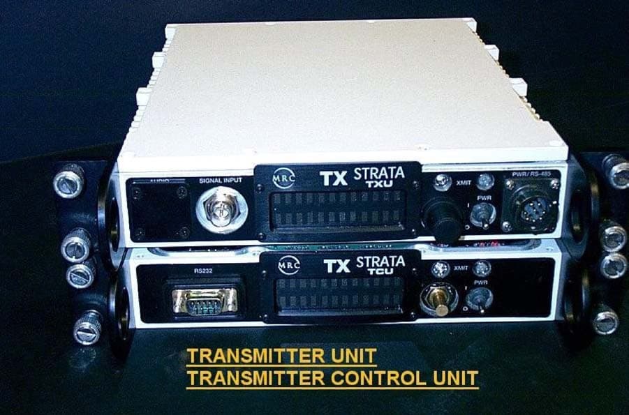
Click to zoom
Application Details
- Equipment Class
- TNB - Licensed Non-Broadcast Station Transmitter
- Date of Grant
- Oct 02, 2003
- Application Purpose
- Original Equipment
- Date of Application
- Oct 02, 2003
- Equipment Note
- STRATA Transmitter
- Frequency Range
- 1990.00000000 - 2700.00000000
- Country
- United States
Documents & Files
Document Text
Text extracted from the exhibit documents filed with the FCC. Open a document above to read the original.
Users Manual
Strata Operations Guide - 1 - Strata Transmitter Operations Guide Revision 3.0 May 2003 Microwave Radio Communications 101 Billerica Avenue, Bldg 6 (978) 671-5700 N. Billerica, MA 01862-1256 www.mrcbroadcast.com WARNING! THIS EQUIPMENT IF HANDLED IMPROPERLY WILL POSE A RADIATION HAZARD Microwave Radio Communications Inc. in compliance with RF exposure limits set forth in OET Bulletin 65, Edition 97-01 utilizes this page for the intent of expressing our concerns to the user of this equipment STRATA 2 GHz Transmitter Unit (TXU) that there exists a radiation hazard with improper use of this equipment. The STRATA transmitter with rated 2-WATT RF Power output is designed as an intentional radiator, as such, this device has been designed to produce and emit radiation into an isotropic antenna for the purpose of delivering a digitally modulated signal to an appropriate receiving device. Due to the low output power of this device in and of itself it poses no such hazard until connected properly and securely to a properly matched antenna. Therefore it is necessary for the equipment operator to be made aware of the safe operating parameters of this device. Below is a chart based on the use of a 5dBi Omni directional antenna. The radiation limits at a distance of below 20cm exceeds the allowable safe exposure limits. Beyond a distance of 20 cm you will notice that the usable antenna gain (expressed in dBi) increases logarithmically with distance spherically from the radiator. In the case of an antenna with a concentrated beam such as a parabolic antenna, the caution to exposure levels would be relative to antenna gain and distance only with in the radiation pattern of the parabola. Notwithstanding, radiation exposure due to antenna inefficiency (side lobe and front to back emission) although severely reduced should be calculated. A case-by-case analysis of each antenna that is to be utilized with this device should be investigated. The intent of this document is to bring awareness to the operator of this device the potential for hazardous RF exposure limits if improperly used. Microwave Radio Communications Inc. cautions the user to contact our customer service department to receive exposure data or the antenna manufacturer to receive the radiation pattern of the antenna if not purchased through Microwave Radio Communications Inc. 101 Billerica Ave., Bldg. 6 N. Billerica, MA 01862-1256 Tel: (978) 671-5700 Fax: (978) 671-5800 RF radiation exposure levels below 1Mw/cm^2 are permissible levels in accordance with OET Bulletin 65, Edition 97-01. The above graph depicts permissible levels at required safe distances from the isotropic radiator. The incremental gain of the radiator can be increased in accordance with the distance of the human body removed from the radiator by the corresponding distance in centimeters. As can be observed, the distances are marginal but notice should be observed never the less. Radiation Limit for Portable Transmitter at 2WATT (+33dBm) MPE Based on 5dBi Omni Antenna mW/cm^2 5dBi Omni 5.02099 -2.007 (Max Allowable Antenna Gain dBi) 2.231555 1.513 1.25525 4.012 0.80336 5.95 0.557889 7.534 0.409877 8.87 0.313812 10.033 0.247951 11.056 0.20084 11.9 0.089262 15.49 Distance cm 10 15 20 25 30 35 40 45 50 75 Strata Operations Guide - 2 - Introduction The Microwave Radio Communications (MRC) Strata system provides a reliable and highly flexible video microwave transport system. This operations guide provides basic system operations information and details for hands-on operation of this equipment. System Description Figure 1 below shows the overall Strata system architecture for a fully equipped system. TCUTXUHPU !NTSC !PAL !SDI !ASI !IF RF OUT RF/DC TelemetryTelemetry IF or Baseband Signal DC Simplex Powering IN Dummy Load 12 v to 48 v DC RS-232 1.84 MHz OOK Tone 12 v to 48 v DC RS-232 Figure 1 – Strata Transmitter System Architecture The primary system features are: oLightweight, Modular, Multi-Unit Design oAnalog, Digital, or Analog/Digital Switchable oMPEG Encoding (4:2:0, 4:2:2) oCOFDM Modulation with Selectable Guard Interval oDigital Modulation for QPSK, 16QAM, and 64QAM oNTSC or PAL Modulation with Audio (4 mono or 2 stereo) oTripod, Half Rack, or Full Rack Mounts oFront Panel Remote Controlled oBands from 2 to 15 GHz oWide Choice of Antennas Note that the TCU (Transmitter Control Unit) and the TXU (Transmitter Unit) may be operated in a stand-alone configuration depending on specific video transport applications. TCU Description The TCU component can accept a wide variety of signal formats and provide several different output signal formats. Figure 2 below shows the basic functions of the TCU. Strata Operations Guide - 3 - MPEG COFDM FMT COAX IN COFDM 70 MHZ MONITOR COAX OUT SDI ASI FMT CV Filter !NTSC !PAL !SDI !ASI !IF MPEG CV Telemetry ASI 70 MHz IF Bypass Note: Either or both MPEG/COFDM or FMT boards may be installed !COFDM !IF CV !IF !ASI IF CV ASI Only Mode Figure 2 - Strata TCU Functional Diagram Note: The TCU may be supplied with or without the MPEG/COFDM or FMT options. TXU Description Like the TCU component, the TXU can accept a wide variety of signal formats but includes an RF up- converter for use in transporting signals over a microwave radio link. Figure 3 below shows the basic functions of the TXU. MPEG COFDM FMT SIGNAL IN ASI MON ASI COFDM 70 MHZ 70 MHZ RF OUT SDI MPEG MPEG CV ASI Input FMT CV !NTSC !PAL !SDI !ASI !IF Filter Telemetry SDI/ASI IF CV IF/RF Up Converter/Amplifier 70 MHz Figure 3 – Strata TXU Functional Diagram Note: The TXU may be supplied with or without the MPEG/COFDM or FMT options. Strata Operations Guide - 4 - HPU Description For those applications requiring a higher RF output level, the HPU (High Power Unit) may be used to boost the signal level to between 2 and 12 watts of microwave output power depending on the modulation format used. Figure 4 below shows the functional architecture of the HPU device. HPURF INRF OUT Figure 4 – HPU Functio…
Text truncated - open the document above for the full version.
Block Diagram
1 2GHZ Two Watt IF/RF MODULE PS1454_OBR_2W_IF_RF.doc PS-1454 Rev 3 14 Jan 2003 3:48pm Revise CX72300 to use 18 bit mode Rev-2 7 Nov 2002 Revised charge Pump Formula, Page 5, Relax Phase Noise Rev-1 13 Nov 2001 RF requirements: Jim Riddle IF/ Microcontroller requirements: Scott Dennison Figure One Block Diagram Figure One shows the block diagram of the IF/RF assembly. The 70 MHz input can be analog or digital. It is upconverted to 900 MHz IF, filtered, then reconverted to an output frequency between 1.99 to 2.7 GHz. The output passes through a step attenuator and a power amplifier. The step attenuator is set to provide the proper linearity for each modulation type and is adjusted across the tuning band. 1.0 ELECTICAL SPECIFICATIONS: 1.1 Frequency Range: 1.99-2.5GHz/2.3-2.7GHz 1.2 Power Output Psat= +33dBm Typ. P(QPSK)= +31dBm Typ. P(16QAM)= +30dBm Typ. 1.3 LO Input: 1.45-1.8GHz @ +3dBm Typ. (HSLO) 1.4 IF Input: Frequency 70 MHz +/- 15 Mhz Impedance 75 ohms 2 Return Loss 24 dB Connector MMCX, (50 ohm version) 1.5 Internal IF: 900MHz @ -10dBm 1.6 Signals In/Out: 2GHz; 50 ohm (SMA) “OOK” Tone (-20dBm) (Feedthru) +10 to + 48VDC @ 6A max. (Feedthru) 1.7 DC Input: +11V @ 1A max. +7V @ .45A max. 1.8 Power Monitor: 1.8.1 DC Voltage for Psat: +.8V to +1.2V 1.8.2 DC Voltage for no RF: <100mV 1.8.3 DC Load Resistance: 10K ohm 1.9 Variable Pout: Adjustable, 30 dB in 1dB steps from P1dB 1.10 Harmonics: <-46dBc (Psat=+33dBm) 1.10.1 Spurious 1.10.1.1 In-Band: <-45dBc 1.10.1.2 Out-of-Band: <-46dBc (Psat= +33dBm) 1.11 DC Connector: 8 pin 2mm connector (AMP 173981-8 ) J8-1 TXD Serial Word to Microcontroller J8-2 RXD Serial Word from Microcontroller J8-3 +7VDC 450 ma Max (150 ma IF section) (300 ma RF section) J8-4 +7 V RTN J8-5 +11 V RTN J8-6 +11 V RTN J8-7 +11 V } 1 A (RF Section) J8-7 +11 V } 1.12 Reference Crystal 1.12.1 Frequency 16 MHz 3 1.12.2 Stability +/- 2 ppm 1.13 Overall Unit 1.13.1 Frequency Stability IF in Transmit out +/- 10 KHz 1.13.2 Phase Noise Foffset dBc/Hz 100 Hz -68 1 KHz -72 10 KHz -82 100 KHz -103 1 MHz -120 2.0 ENVIRONMENTAL SPECIFICATIONS: 2.1 Operating Temp. Range: -30deg C to +70deg C case temp. 3.0 PHYSICAL SPECIFICATIONS: 3.1 RF Output: SMA female 3.2 Vbias Tee/OOK: Capacitive feedthru (47pF) 3.3 GND: Solder lug 3.4 IF Input MMCX female (50 ohm type) 75 ohm 3.5 DC Connector 8 pin 2mm header AMP 173981-8 3.6 Test Connector 16 pin SULLINS PPPN162GFNS 4.0 Microcontroller functions: The serial control word enables all the functions, RF switches and an attenuator. Lock detect status and power amp detector voltages are returned on the serial data line. Bill Brown and his software department will determine the protocol for these RXD and TXD lines. Whenever the module is powered on, the RF power amplifier must be disabled until all the oscillators have locked up. The unit shall reset to the last set of programmed frequencies and switch settings. A test tune algorithm will be developed to sweep the sources across the entire band and learn the 5 bit attenuator settings. It is expected that we will copy the Code Runner approach. The test tune algorithm will be available to the factory but not the end user. 4.1 Microwave Attenuator A 5 bit digital attenuator precedes the RF power amplifier. The function is to back off the signal levels to achieve the needed amount of signal linearity. Some gain adjustment is also used 4 to compensate for amplitude ripples in the amplifier. The attenuator steps from 0 dBr to 31 dBr in 1 dB steps. The polarity of the control line is active low, with 5 volts at high. 4.2 ADC inputs Three lines are sampled by input Analog to Digital Converters (ADC): The RF power detect, UHF lock detect and RF lock detect. The value of the RF power detector, and the status of the lock detect lines ( locked/unlocked) is sent back to the external controller 4.3 LED outputs The microcontroller samples the Si4133 lock detect ( U_LOCK) and the CX72300 lock detect ( R_LOCK ) , then enables the corresponding LEDs. U_LOCK lock < 0.5 V Unlock > 1.5 V U_LOCKED locked = output low Unlocked = open drain R_LOCK lock > 2.0 V Unlock < 1.0 V R_LOCKED locked = output low Unlocked = open drain 4.4 UHF synthesizer The UHF local oscillator is generated with a Silicon Labs Si4133 UHF synthesizer. This device has two on board VCOs, integrated loop filters and phase lock loops. The RF frequency is set to a nominal 970 MHz. 830 MHz may be selected if the spectrum is inverted. The RF reference divider is set to 16 in each case for a phase detector frequency of 1 MHz. The IF section is powered down. 4.4.1 Si 4133 parameters : AUXSEL = 011 = Lock detect IFDIV = xx = IF VCO Divider LPWR = 0 = “< 500 ohms” XPDM = 0 = Ref Amp Pwr Dwn at D=0 AUTOPBD = 0 = Software controlled Pwr Dn AUTOKP = 0 = Kp gain set by software Write to RF2 register ( RF1 not used ): PDAB = 1 = Reference Amp on PDIB = 0 = IF synthesizer on PDRB = 1 = RF synthesizer on 5 KP2 = 00 = RF2 Phase Detect. Gain = 1 NRF2 = 970 = Output Freq = 970 MHz RRF2 = 16 = Phase detector freq = 1MHz KPI = xx = IF Phase Detector Gain = ½ NIF = xx = IF VCO Freq = 633 1/7 MHz ( divided by 8 output = 79 1/7 MHz) RIF = xx = Phase detector freq = 2/7 MHz 4.5 Microwave synthesizer 4.5.1 CX 72300 parameters: A Skyworks (Philsar/Conexant ) CX72300 synthesizer is used to tune the microwave VCO. The VCO is followed by a frequency doubler and the output frequency is 900 MHz above the transmitted frequency. We only use the main synthesizer. The auxiliary synthesizer is powered down. Direct Modulation, Frequency Power Steering and Modulation Data are not used. The CX72300 RF synthesizer will tune 1445 to 1800 MHz. The preferred mode of 18 bit resolution can be used to meet any future 2 GHz frequency plan. The frequency step size, with a reference frequency of 16 MHz and 18 bit mode, will be 122.0703125 Hz ( 16MHz x 2 / 2^18 ). The VCO frequency is calculated from: 4.5.2 Fvco = ( Ftransmitter + 900 MHz ) / 2 Example: If Radio transmits at 2500 MHz, Set VCO frequency t…
Text truncated - open the document above for the full version.
Cover Letter(s)
Response to TCB Findings 1. Please point out the section, where we can find the DC voltages and currents in the final RF amplifier stage of the transmitter module. The D.C. voltages are listed in detail on the schematic for the RF/IR assy. Part# 907374 2. Please supply tune-up procedure. Tune-up procedure is not applicable for this device as there are no features that are user assessable to allow alteration of the frequency. The source is synthesized highly stable (can be seen in test report) which leaves no active tunable circuits. The manipulation of predefined channel selection, control of the MPEG encoder is accusable via front panel control. No adjustments are capable of altering the bandwidth. 3. Please specify the nominal operating voltage of the device 28VDC is the nominal operating voltage for the device.
External Photos
STRATA TRANSMITTER REAR VIEW AT CONTROL AND ANTENNA CONECTION FIGURE 9 16 STRATA TRANSMITTER TOP AND FRONT VIEW 17 STRATA TRANSMITTER UTILIZING EXTERNAL TXU (BASEBAND AND CONTROL UNIT) FIGURE 9B 18
ID Label/Location Info
FCC LABEL LOCATION 15 FCC ID LABLE
RF Exposure Info
Equation from page 18 of OET Bulletin 65, Edition 97-01 w here:S = pow er density P = pow er input to the antenna G = pow er gain of the antenna in the direction of interest relative to an isotropic radiator R = distance to the center of radiation of the antenna Maximum peak output pow er at antenna input terminal:33.00(dBm) Maximum peak output pow er at antenna input terminal:1995.2623(mW) A ntenna gain(typical):5(dBi) Maximum antenna gain:3.1622777(numeric) Prediction distance:23(cm) Prediction frequency:2700(MHz) MPE limit for uncontrolled exposure at prediction frequency:1(mW/cm^2) Pow er density at prediction frequency:0.949149(mW/cm^2) Maximum allow able antenna gain:5.2266554(dBi) 2 4R PG S π = This prediction is predicated on the use of a 5dBi omni directional antenna. The antenna typically roof mounted atop an Electronic News Gathering Vehicle or on the bottom of an Airborne platform such as a helicopter, fixed wing of other vehicle. Other antenna selections are covered under the Hazardous radiation warning in the STRATA operators manual.
Test Report
APPLICATION FOR CERTIFICATION OF STATXU2D PORTABLE MICROWAVE TRANSMITTER SEPTEMBER 15, 2003 101 Billerica Ave., Bldg. 6 N. Billerica, MA 01862-1256 Tel: (978) 671-5700 Fax: (978) 671-5800 TABLE OF CONTENTS SECTION 1 INTRODUCTION PAGE TECHNICAL DESCRIPTION 1 MEASUREMENT DATA Spurious emissions at antenna terminal 2 Field strength of Spurious Radiation 3 Necessary and Occupied Bandwidth 4 Frequency Stability and Power Output 5 EMISSION DESIGNATOR 5 ENGINEERIN CERTIFICATION 5 SECTION 2 FCC LABEL AND PLACEMENT PHOTO SECTION 3 2GHz 2W RF/IF MODULE SECTION 4 STRATA TRANSMITTER USERS’ MANUAL I 101 Billerica Ave., Bldg. 6 N. Billerica, MA 01862-1256 Tel: (978) 671-5700 Fax: (978) 671-5800 SECTION 5 STRATA TRANSMITTETR DIAGRAMS and SCHEMATICS PAGE 907364 TXU Power Supply 1 – 11 907216 Display and Rotary Encoder Controller 12 - 15 907462 Cable Equalizer 16 – 18 907374 RF 2 WATT RF- IF 19 - 24 LIST OF FIGURES FIGURE DESCRIPTION PAGE 1 Spurious Emissions at Antenna Test Set-up 6 2 Field Strength of Spurious Radiation Test Set-up 7 3 Modulation Characteristics Test Ste Up 8 4 Video Test Signal 9 5 Occupied Bandwidth Spectrum 10 6A RF Output Power and Frequency Test Set Up 11 6B Frequency stability vs primary DC power 11 7 Attestation Test Set Up 12 8 Photograph of STATXU2D (includes FCC label) 15 9 Photograph of STATXU2D Transmitter (rear view) 16 TABLE DESCRIPTION PAGE 1 Frequency Stability Test Data 13 2 Test Equipment 14 ii 101 Billerica Ave., Bldg. 6 N. Billerica, MA 01862-1256 Tel: (978) 671-5700 Fax: (978) 671-5800 Introduction: The STATXU2D is a general mobile transmitter designed for use in the 1999 Mhz. to 2700 Mhz. band. Emissions: 17M0D9W (Digital Modulation) Operation under FCC rule parts 74, 78, 90 101 Application: For transmission of video, audio, data, and related Television Broadcast program material from events occurring at points removed from the TV Broadcast station or other users. A compact, portable, weatherproof, modular transmitter. Designed to be adaptable over a wide range of outdoor field applications, The transmitter accepts a wide range of SMPTE defined video inputs (SDI, ASI, NTSC...) delivered to a highly integrated internal MPEG-2 Encoder and COFDM modulator. A front panel LED display details the internal RF and Baseband configurations. Status display of frequency, power, modulation, and RF output... is also viewable from the same LED display. The STRATA TX can be deployed as a single or multi box configuration. The Transmitter (TXU) is be deployed as a single box digital transmitter utilizing an internal COFDM modulator and MPEG-2 encoder. A two-box design utilizing a transmitter control unit (TCU) places the baseband units internal to the TCU outputting 70MHz. To the TXU. The TXU is complete with the RF Amplifier and Up-Converter, the Baseband components integrated into the TCU. The TCU provides control and RF (70MHz) as drive to the RF Up-Converter. System control can be displaced from the RF unit by as much as 100 meters. For the sake of this application the unit (TXU) is configured as a Digital Transmitter with internal COFDM modulator and MPEG-2 encoder. Digital Modulation: A COFDM architecture utilizing QPSK modulation has been integrated into the STRATA design. The imbedded control allows the user to select various digital modulation formats while maintaining the specifications as set forth by ETSI TR 101 190 v1.1.1 for Digital Video Broadcasting. Output of the modulator at 70 MHz. is applied to the input to the transmitter, frequency is selected, and the RF output is delivered to the antenna. 1 101 Billerica Ave., Bldg. 6 N. Billerica, MA 01862-1256 Tel: (978) 671-5700 Fax: (978) 671-5800 TECHNICAL DESCRIPTION A technical description is contained within the manual MEASUREMENT DATA In Order to demonstrate compliance to the FCC Rules and Regulations as set forth in CFR 47 (as revised October 1, 2002), measurement data per paragraphs2.1046, 2.1047, 2.1049, 2.1051, 2.1053, 2.1055 where performed at Microwave Radio Communications facilities. The results of these measurements show that the STATXU2D transmitter meets or exceeds all requirements for parts 74, 78, 90 and 101. SPURIOS EMISSIONS AT ANTENNA TERMINAL The Antenna conducted spurious emissions test set up is shown in Figure 1. The analyzer was first tuned for a reference carrier level at the fundamental operating frequency. The output spectrum was then slowly scanned from 50MHz to 26 GHz. Special attention was given to those frequencies that correspond to the possible harmonic and sub – harmonics. The FCC limit for antenna conducted spurious emissions is 43+10LOG P below the main carrier. For the STATXU2D with P= 1.76 W this corresponds to 45.4551db below the main carrier (+32.6dbm) , or a level of –12.95dBm. Signals where observed at the following points: 900 MHz @ –30.4dBm 2950 MHz @ -22.4dBm 4101 MHz @ -27.7dBm 6151.5 MHz @ -32.4dBm * Frequencies within 20db of FCC specification With the exception of the above noted points, no other signals were noted within 20db of the FCC limit. Therefore, the STATXU2D meets the requirements set forth in paragraphs , 74.637, 78.103, 90.209, and 101.111. 2 101 Billerica Ave., Bldg. 6 N. Billerica, MA 01862-1256 Tel: (978) 671-5700 Fax: (978) 671-5800 FIELD STRENGTH OF SPURIOUS RADIATION Case radiated spurious emission test set up is shown in figure 2. Observations where made at one meter from the transmitter in all planes of polarization. The output spectrum as received at one meter was slowly scanned upwards from 50MHz to 26GHz. Spacial attention was given to those frequencies which correspond to possible harmonics and sub harmonics. A radiated reference level can be calculated using the formula: 30xGxP R E = Where: G = Power Gain of Antenna P = Transmitter Power Output in Watts R = Distance from Radiator at which field intensity is measured. In this case: G = 1.64 (gain of dipole over isotropic) P = 1.76 R = One Meter Therefore: 30x1.64x1.76 1 E = = 9.3055V/meter = 139.4…
Text truncated - open the document above for the full version.
Test Report
-50 dB -8.5 MHZ 0 REF -50 dB +8.5 MHZ -50 dB -8.5 MHZ 0 REF -50 dB +8.5 MHZ -50 dB -8.5 MHZ 0 REF -50 dB +8.5 MHZ -50 dB -8.5 MHZ 0 REF -50 dB +8.5 MHZ -50 dB -8.5 MHZ 0 REF -50 dB +8.5 MHZ -50 dB -8.5 MHZ 0 REF -50 dB +8.5 MHZ
Test Setup Photos
ATTESTATION TEST SET UP FIGURE 7 12
Contact Information
Applicant
Richard Miller(Lead Solutions Engineer)
Technical Specifications
| # | Rule Parts | Frequency Range | Power Output | Emission | Tolerance |
|---|---|---|---|---|---|
| 3 | 74,9 | 1.99 GHz - 2.70 GHz | 2 W | 16M0W7D | 2 ppm |
Other Applications from Microwave Radio Communications LLC
FC3NST2G7G
Nov 09, 2015Microwave Mobile Transmitter
Equipment Class
TNB - Licensed Non-Broadcast Station Transmitter
FC3L32112GAMP
Mar 09, 2014Booster Amp
Equipment Class
AMP - Amplifier
FC3HDX2025D
Jun 04, 2013Microwave Downlink transmitter
Equipment Class
TNB - Licensed Non-Broadcast Station Transmitter
FC3HDX064D
Sep 11, 2011Microwave Downlink Transmitter
Equipment Class
TNB - Licensed Non-Broadcast Station Transmitter
FC3PTX270AD
Aug 03, 2011PTX-PRO Transmitter
Equipment Class
TNB - Licensed Non-Broadcast Station Transmitter