G8JEAGAS01EnergyAxis Gas Module
Elster Solutions, LLC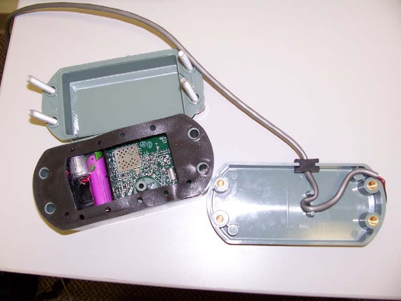
Click to zoom
Application Details
- Equipment Class
- DSS - Part 15 Spread Spectrum Transmitter
- Date of Grant
- Dec 16, 2007
- Application Purpose
- Original Equipment
- Date of Application
- Dec 16, 2007
- Equipment Note
- EnergyAxis Gas Module
- Frequency Range
- 902.80000000 - 927.60000000
- Company
- Elster Solutions, LLC
- Country
- United States
Documents & Files
Document Text
Text extracted from the exhibit documents filed with the FCC. Open a document above to read the original.
Users Manual
U U U S S S E E E R R R G G G U U U I I I D D D E E E E E n n e e r r g g y y A A x x i i s s G G a a s s M M o o d d u u l l e e TABLE OF CONTENTS EnergyAxis Gas Module ― User Guide Page i Elster Integrated Solutions • P/N 52870T010 Rev 3 March 2007 Copyright Acknowledgements The contents of this document are the property of Elster Integrated Solutions and are copyrighted. All rights reserved. Any reproduction, in whole or in part, is strictly prohibited. For additional copies of this document, please contact: Elster Integrated Solutions 208 South Rogers Lane Raleigh, NC 27610 Phone 919-250-5700 Fax 919-250-5439 The information contained herein has been carefully checked and is believed to be accurate; however, no responsibility is assumed for inaccuracies. Elster Integrated Solutions reserves the right to make changes without prior notice. This document is not covered by any warranty either expressed or implied. Any correction, comments or additions to the contents of this document should be directed to Elster Integrated Solutions at the above address. Copyright 2003 Elster Integrated Solutions. Printed in USA. EnergyAxis are trademarks of Elster Integrated Solutions. All rights reserved. Page ii EnergyAxis Gas Module ― User Guide Elster Integrated Solutions • Draft Rev A Nov. 2007 FCC & Industry Canada Compliance EnergyAxis Gas Module™ has been granted authorization as a low power modular radio transmitter by the Federal Communications Commission under 47 CFR Part 15.247 and by Industry Canada under RSS-GEN and RSS-210. FCC ID: G8JEAGAS01. Industry Canada ID: 3599-EAGAS01. The device transmits and receives in the frequency range 902.8 – 927.6 MHz. The device may also receive on 451.35 MHz. The user of this device must maintain a distance of 20cm between the device and any part of the human body, to comply with FCC RF exposure requirements. This device complies with FCC Part 15 & Industry Canada RSS-GEN/RSS- 210 rules. Operation is subject to the following conditions: 1. This device may not cause harmful interference, and 2. This device must accept any interference received, including interference that may cause undesired operation. This equipment has been tested and found to comply with the limits for a Class B digital device, pursuant to Part 15 of the FCC Rules. These limits are designed to provide reasonable protection against harmful interference in a residential installation. This equipment generates uses and radiates radio frequency energy, and if not installed and used in accordance with the instructions, may cause harmful interference to radio communications. However, there is no guarantee that interference will not occur in a particular installation. If this equipment does cause harmful interference to radio or television reception, which can be determined by turning the equipment off and on, the user is encouraged to try to correct the interference by one or more of the following measures: • Reorient or relocate the receiving antenna. • Increase the separation distance between the equipment and receiver. • Connect the equipment into an outlet on a circuit different from that to which the receiver is connected (not applicable for the battery-powered EnergyAxis Gas Module™). • Consult the equipment dealer or an experienced radio/TV technician for help. WARNING! Changes or modifications not expressly approved by Elster Integrated Solutions void the user’s authority to operate the equipment. TABLE OF CONTENTS EnergyAxis Gas Module ― User Guide Page i Elster Integrated Solutions • P/N 52870T010 Rev 3 March 2007 EnergyAxis Gas Module USER GUIDE Table of Contents Chapter One.............................................................................................. 1 Introduction ......................................................................................................................................... 1 About this Document 1 Chapter Two..................................................................................................................................... 3 Automated Meter Reading Overview................................................................................................. 3 Basic AMI Components 3 EnergyAxis AMI System Overview 4 Chapter Three.................................................................................................................................. 5 EnergyAxis Direct Gas-meter Transponder Overview .................................................................... 5 EnergyAxis Direct Gas-meter Transponder and Components 6 How the EnergyAxis Direct Gas-meter Transponder Works 9 Specifications 10 Chapter Four................................................................................................................................... 11 EnergyAxis Direct Gas-meter Transponder Installation ............................................................... 11 Tools, Equipment and Materials 11 Preparation and Installation 12 Programming the EnergyAxis Direct Gas-meter Transponder 17 Chapter Five................................................................................................................................... 19 EnergyAxis Remote Gas-meter Transponder Overview ............................................................... 19 How it Works 20 Features and Capabilities 20 EnergyAxis Remote Gas-meter Transponder Construction 20 Identifying the Components (Meter Mount) 22 Chapter Six..................................................................................................................................... 23 EnergyAxis Remote Gas-meter Transponder Installation ............................................................ 23 Tools, Equipment and Materials 23 Pulser Installation (Meter-mount) 24 EnergyAxis RGT Mounting (Meter-mount) 30 EnergyAxis RGT Programming (All) 34 Appendix................................................................................................................................…
Text truncated - open the document above for the full version.
Internal Photos
Elster Integrated Solutions, LLC 208 S. Rogers Lane Raleigh, NC 27610 EnergyAxis Gas Module (Model #5D25575) Internal And External Photos 2 Figure 1. EnergyAxis Gas Module with battery and switch cable (SHIELD COVERS REMOVED) 3 Figure 2. EnergyAxis Gas Module with Battery and Switch Cable (SHIELD COVERS IN PLACE) 4 Figure 3. EnergyAxis Gas Module, rear. Battery and Switch cable are not shown. “L”-SHAPED SLOT ANTENNA FCC/IC ID LABEL GOES HERE 5 Figure 4. EnergyAxis Gas Module in typical gas meter housing (American, Standalone), with cover removed to show the module.
RF Exposure Info
Report Number: 30762680.002 MPE Page 1 of 3 EUT: Energy Axis Gas Module Model: 5D25575 33_EME/I 01/29/2001 RF Exposure Report EUT Name: Energy Axis Gas Module EUT Model: 5D25575 FCC Title 47, Part 15.247(i), 1.1307(b), and 1.1310 Prepared for: Steve Bragg Elster Electricity, LLC 208 South Rogers Lane Raleigh, NC 27610 Tel: 919 212-4700 Fax: 919 212-5108 Prepared by: TUV Rheinland of North America 762 Park Avenue Youngsville, NC 27596 Tel: (919) 554-0901 Fax: (919) 556-2043 http://www.tuv.com/ Report/Issue Date: 17 December 2007 Report Number: 30762680.002 MPE TUV Rheinland of North America FCC ID: QZC-R2EA 762 Park Ave., Youngsville, NC 27596 Tel: (919) 554-3668, Fax: (919) 554-3542 Report Number: 30762680.002 MPE Page 2 of 3 EUT: Energy Axis Gas Module Model: 5D25575 33_EME/I 01/29/2001 1.1 RF Exposure Measurement (Mobile Device) 15.247(i) 1.1.1 Test Methodology In this document, we try to prove the safety of radiation harmfulness to the human body for our product. The limit for Maximum Permissible Exposure (MPE) specified in FCC 1.1310 is followed. The Gain of the antenna used in this product is measured in a Semi-Anechoic Chamber, and also the maximum total power input to the antenna is measured. Through the Friis transmission formula (see section 4.9.6) and the maximum gain of the antenna, we can calculate the distance, away from the product, where the limit of MPE is reached. Although the Friis transmission formula is a far field assumption, the calculated result of that is an over- prediction for near field power density. We will take that as the worst case to specify the safety range. 1.1.2 RF Exposure Limit According to FCC 1.1310 table 1: The criteria listed in the following table shall be used to evaluate the environmental impact of human exposure to radio-frequency (RF) radiation as specified in 1.1307(b) LIMITS FOR MAXIMUM PERMISSIBLE EXPOSURE (MPE) Frequency Range (MHz) Electric Field Strength (V/m) Magnetic Field Strength (A/m) Power Density (mW/cm 2) Average Time (minutes) (A)Limits For Occupational / Control Exposures 300-1500 ... ... F/300 6 1500-100,000 ... ... 5 6 (B)Limits For General Population / Uncontrolled Exposure 300-1500 ... ... F/1500 6 1500-100,000 ... ... 1.0 30 F = Frequency in MHz TUV Rheinland of North America FCC ID: QZC-R2EA 762 Park Ave., Youngsville, NC 27596 Tel: (919) 554-3668, Fax: (919) 554-3542 Report Number: 30762680.002 MPE Page 3 of 3 EUT: Energy Axis Gas Module Model: 5D25575 33_EME/I 01/29/2001 1.1.3 EUT Operating condition The software provided by Manufacturer enabled the EUT to transmit data at lowest, middle and highest channel individually. 1.1.4 Classification The antenna of the product, under normal use condition, is at least 20cm away from the body of the user. Warning statement to the user for keeping at least 20cm or more separation distance with the antenna should be included in users manual. So, this device is classified as a Mobile Device. 1.1.5 Test Results 1.1.5.1 Antenna Gain The maximum Gain measured in Semi-Anechoic Chamber is 2.53 dBi or 1.79 (numeric). 1.1.5.2 Output Power into Antenna & RF Exposure value at distance 20cm: Calculations for this report are based on highest power measurement and the highest gain of the antenna. Limit for MPE (from FCC part 1.1310 table 1) is f(Mhz) / 1500 = 0.6 mW/cm 2 Highest Pout is 190mW, highest antenna gain (in linear scale) is 1.79, and R is 20cm. Pd = (190*1.79) / (1600π) = 0.068 mW/cm 2 As originally tested, the EUT was found to be compliant to the requirements of the test standard(s). 1.1.6 Sample Calculation The Friis transmission formula: Pd = (Pout*G) / (4*π*R 2 ) Where; Pd = power density in mW/cm 2 Pout = output power to antenna in mW G = gain of antenna in linear scale π ≈ 3.1416 R = distance between observation point and center of the radiator in cm Ref. : David K. Cheng, Field and Wave Electromagnetics, Second Edition, Page 640, Eq. (11-133).
Test Report
Report Number: 30762680.001 Page 1 of 30 EUT: Energy Axis Gas Module Model: 5D25575 33_EME/I 01/29/2001 Emissions Test Report EUT Name: Energy Axis Gas Module EUT Model: 5D25575 FCC Title 47, Part 15, SubpartC, RSS-210 Issue 7 Prepared for: Steve Bragg Elster Electricity, LLC 208 South Rogers Lane Raleigh, NC 27610 Tel: 919 212-4700 Fax: 919 212-5108 Prepared by: TUV Rheinland of North America 762 Park Avenue Youngsville, NC 27596 Tel: (919) 554-0901 Fax: (919) 556-2043 http://www.tuv.com/ Report/Issue Date: 02 January 2007 Report Number: 30762680.001 Statement of Compliance Report Number: 30762680.001 Page 2 of 30 EUT: Energy Axis Gas Module Model: 5D25575 33_EME/I 01/29/2001 Manufacturer: Elster Electricity, LLC 208 South Rogers Lane Raleigh, NC 27610 919 212-4700 Requester / Applicant: Steve Bragg Name of Equipment: Energy Axis Gas Module Operation Frequency Range 902.8 MHz to 927.6 Type of Equipment: Intentional Radiator Application of Regulations: FCC Title 47, Part 15, SubpartC, RSS-210 Issue 7 Test Dates: 26 November 2007 to 28 November 2007 Guidance Documents: Emissions: FCC 47 CFR Part 15, RSS-210 Issue 7 Test Methods: Emissions: ANSI C63.4:2003 The electromagnetic compatibility test and documented data described in this report has been performed and recorded by TUV Rheinland of North America, in accordance with the standards and procedures listed herein. As the responsible authorized agent of the EMC laboratory, I hereby declare that a sample of one, of the equipment described above, has been shown to be compliant with the EMC requirements of the stated regulations and standards based on these results. If any special accessories and/or modifications were required for compliance, they are listed in the Executive Summary of this report. This report must not be used to claim product endorsement by NVLAP or any agency of the U.S. Government. This report contains data that are not covered by NVLAP accreditation. This report shall not be reproduced except in full, without the written authorization of the laboratory. 14 December 2007 NVLAP Signatory Date Industry Canada 200094-0 90552 and 100881 IC3755 200094-0 Table of Contents Report Number: 30762680.001 Page 3 of 30 EUT: Energy Axis Gas Module Model: 5D25575 33_EME/I 01/29/2001 1 EXECUTIVE SUMMARY................................................................................................................. 4 1.1 SCOPE............................................................................................................................................ 4 1.2 PURPOSE........................................................................................................................................ 4 1.3 SUMMARY OF TEST RESULTS........................................................................................................ 5 1.4 SPECIAL ACCESSORIES.................................................................................................................. 6 1.5 EQUIPMENT MODIFICATIONS........................................................................................................ 6 2 LABORATORY INFORMATION ................................................................................................... 6 2.1 ACCREDITATIONS & ENDORSEMENTS.......................................................................................... 6 2.2 TEST FACILITIES............................................................................................................................ 7 2.3 MEASUREMENT UNCERTAINTY..................................................................................................... 8 2.4 CALIBRATION TRACEABILITY....................................................................................................... 8 3 PRODUCT INFORMATION ............................................................................................................8 3.1 EQUIPMENT CONFIGURATION....................................................................................................... 8 4 EMISSIONS ........................................................................................................................................ 9 4.1 CHANNEL SEPARATION PART 15.247(A)(1) .................................................................................. 9 4.2 PSEUDORANDOM HOPPING ALGORITHM FCC PART 15.247(A)(1) ............................................. 10 4.3 OCCUPIED BANDWIDTH FCC PART 15.247(A)(1)(I) ................................................................... 13 4.4 BAND EDGE COMPLIANCE FCC PART 15.215(C) ........................................................................ 16 4.5 PEAK OUTPUT POWER FCC PART 15.247(B)(2).......................................................................... 18 4.6 ANTENNA.................................................................................................................................... 20 5 EMISSIONS ...................................................................................................................................... 20 5.1 RADIATED EMISSIONS................................................................................................................. 20 5.2 SPURIOUS EMISSIONS FCC PART 15.247(C) ............................................................................... 21 5.3 FREQUENCY STABILITY FCC PART 15.215(C) ............................................................................ 27 5.4 CONDUCTED EMISSIONS PER FCC PART 15.207 ......................................................................... 29 6 TEST EQUIPMENT USE LIST ...................................................................................................... 30 TEST EQUIPMENT USE LIST..................................................................................................................... 30 TUV Rheinland of North America FCC ID G8JEAGAS01 762 Park Ave., Youngsville, NC 27596 Tel: (919) 554-3668, Fax: (919) 554-3542 R…
Text truncated - open the document above for the full version.
Test Setup Photos
Test Setup Photos Transmitter Conducted Measurements Radiated Measurement Setup Radiated Measurement Setup
Contact Information
Applicant
Steve Bragg(Sr. RF Engineer)
Technical Contact
Elster Intergrated Solutions, LLCSteve Bragg
[email protected]919 250 5475
208 South Rogers Lane · Raleigh, North Carolina · United States
Non-Technical Contact
Elster Intergrated Solutions, LLCAmy Biedny
919 212 4732
Test Firm
TUV Rheinland of North AmericaMichael Moranha
Technical Specifications
| # | Rule Parts | Frequency Range | Power Output |
|---|---|---|---|
| 1 | 15C | 902.8 MHz - 927.6 MHz | 190.00 mW |
Other Applications from Elster Solutions, LLC
G8JEAMOBILE1
Jan 13, 2013Vehicle-Based Mobile Wireless Meter Reading Equipment
Equipment Class
TNB - Licensed Non-Broadcast Station Transmitter
G8JHHI05
Oct 14, 2012PI900W
Equipment Class
DXX - Part 15 Low Power Communication Device Transmitter
G8JHHI04
Jan 16, 2008Hand Held Interrogator
Equipment Class
TNB - Licensed Non-Broadcast Station Transmitter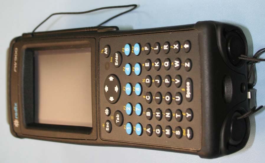
G8JHHI03
Jan 09, 2008PI900 Handheld Interrogator
Equipment Class
DSS - Part 15 Spread Spectrum Transmitter
G8JHHI01
Feb 06, 2005VRT Hand Held Interrogator
Equipment Class
TNB - Licensed Non-Broadcast Station Transmitter