G8JMMI01Mini-Mobile Interrogator
Elster Solutions, LLC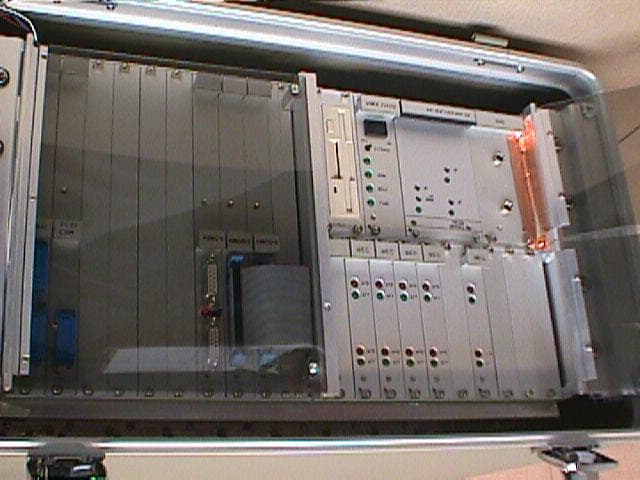
Click to zoom
Application Details
- Equipment Class
- TNB - Licensed Non-Broadcast Station Transmitter
- Date of Grant
- Mar 25, 1999
- Application Purpose
- Original Equipment
- Date of Application
- Dec 28, 1998
- Equipment Note
- Mini-Mobile Interrogator
- Frequency Range
- 450.00000000 - 460.00000000
- Company
- Elster Solutions, LLC
- Country
- United States
Documents & Files
Document Text
Text extracted from the exhibit documents filed with the FCC. Open a document above to read the original.
Users Manual
Table of Contents 1. Overview ____________________________________________________________ 0 1.1 System Components ______________________________________________________ 1 2. Setup _______________________________________________________________ 2 3. Controls & Indicators__________________________________________________ 3 3.1 Power Supply____________________________________________________________ 3 3.2 Power/Status Panel _______________________________________________________ 4 3.3 Transmitter/Receiver _____________________________________________________ 5 4. Operation ___________________________________________________________ 6 4.1 Reading Mode ___________________________________________________________ 6 4.1.1 GPS Operation &Alarms________________________________________________________ 9 4.2 Performance Enhancement Features _______________________________________ 10 4.2.1 GEO Mode _________________________________________________________________ 10 4.2.2 Dynamic Window ____________________________________________________________ 11 4.2.3 Frequency Scan ______________________________________________________________ 11 4.3 Command Mode ________________________________________________________ 12 4.3.1 Summary Command __________________________________________________________ 12 4.3.2 Tools Command _____________________________________________________________ 17 4.3.3 Quit Command ______________________________________________________________ 27 4.3.4. Help Command _____________________________________________________________ 29 5. Troubleshooting _____________________________________________________ 32 Appendix A: File Formats _______________________________________________ 33 A.1 GUIDE File ____________________________________________________________ 33 A.2 READING.RTE File ____________________________________________________ 34 A.3 .VAN File______________________________________________________________ 36 Appendix B: Specifications ______________________________________________ 37 List of Figures Figure 1. Mini-MI ______________________________________________________ 1 Figure 2. MMI Status Indicators __________________________________________ 3 Figure 3. Transmitter/Receiver Status Indicators _____________________________ 5 Figure 4. Reading Mode Display ___________________________________________ 8 Figure 5. Summary Command Menus _____________________________________ 12 Figure 6. Summayr Display Data Format __________________________________ 13 Figure 7. Tools Command Menus_________________________________________ 17 Figure 8. Trouble Shoot Display __________________________________________ 18 Figure 9. System Setup Menu ____________________________________________ 20 Figure 10. Route Scan Menu_____________________________________________ 22 Figure 11. Backup Memory Menus________________________________________ 23 Figure 12. Frequency Control Menu ______________________________________ 24 Figure 13. Set Perm Menu_______________________________________________ 26 Figure 14. Quit Command Menus_________________________________________ 27 Figure 15. Help Command Menus ________________________________________ 29 Figure 16. Location & Time Menu ________________________________________ 30 Figure 17. Set Time & Date Menu ________________________________________ 31 Figure 18. READING.RTE Header Format_________________________________ 34 Figure 19. READING.RTE Record Format _________________________________ 34 Figure 20. READING.RTE Example File __________________________________ 35 Figure 21. VAN File Header Format ______________________________________ 36 Figure 22. VAN File Record Format ______________________________________ 36 Figure 23. VAN File Example ____________________________________________ 36 Chapter 1 Overview Chapter 1: Trace MMI Overview The Trace ® Mini-Mobile Interrogator (MMI) is a portable data retrieval and storage system designed to provide remote meter reading in conjunction with the Trace meter transponders. The Trace system is designed to convert the mechanical index reading of a utility meter to a duplicate electronic register reading. This electronic register reading is transmitted via radio frequency (RF) signals to the MMI. The Trace MMI reads each transponder by use of an RF interrogation that consists of a unique serial number along with a command requesting the contents of the electronic register. Each transponder is selected for reading on either a first-in-first-out (FIFO) basis, a latitude/longitude (L/L) basis, or a combination of the two GEO mode. The MMI obtains route data from a customer supplied floppy disk containing the street address, latitude/longitude , and serial number of each transponder that is to be read. The MMI uses a GPS-based navigation system that tracks the vehicle position. If the Lat/Lon mode of interrogation has been selected, whenever the MMI comes into the range of a particular transponder it begins to send an interrogation for that unit. When the transponder receives a signal with the correct serial number it transmits its electronic register reading, tamper status, and an error detection code. The MMI listens for each transponder reply using an 8-channel receiver. Reply data integrity is confirmed by monitoring receiver data tracking signals and by an error detection code known as a BCH code. A transponder reply is only accepted if the BCH code analysis is valid. This ensures that the data was received without error. The meter reading along with transponder status, receiver channel activity, time of the read, and vehicle position at the time of the read is stored in an output file contained on a floppy disk. Once the MMI has been initialized with the appropriate route data, the system will collect readings automatically, allowing the operator to drive the route in a safe and efficient manner. Chapter 1 Overview MMI System Components Figure 1. Mini-MI The MMI system consists of several main components, as displayed in figure 1. …
Text truncated - open the document above for the full version.
Attestation Statements
Mr. Erol Chang Per your request see the following attachements.
Cover Letter(s)
Federal Communications Commission Chief Authorization Branch Authorization & Evaluation Division 7435 Oakland Mills Road Columbia, MD 21046 January 4, 1999 Subject: American Meter, FCC ID: G8JMMI01 I would like to apologize for the following error. The pictures for test set up, section 7.0, page 32 were mistakenly submitted on December 30, 1998. The pictures provided were used for engineering investigation purposes only. Please find attached (now submitted to 'add attachments' January 4, 1999 of the equipment, as tested at Rhein Tech Labs in final radiated emission testing. Thank you, Linda Harrison
External Photos
980482 Figure 18: EUT front panel view Figure 19: Close up view 980482 FCC ID Label goes here. Figure 20: Back of EUT with cover showing FCC ID label placement Figure 21: Control Panel, front 980482 Figure 22: Control Panel, back
ID Label/Location Info
American Meter Co. 2.0PRODUCT LABELING FIGURE 1: FCC ID LABEL This device complies with the FCC, part 15 rules. Operation is subject to the following two conditions: 1) This device may not cause harmful interference. 2) This device must accept any interference received, including interference that may cause undesired operation. FCC ID: G8JMMI01 FIGURE 2: LOCATION OF LABEL ON EUT Back of Unit Label: 1.2 height, 2.9 width Location of FCC ID Label
Internal Photos
980482 Figure 23: Power regulating circuit Figure 24: Rear view of power supply 980482 Figure 25: MMI Power Status, back Figure 26: Floppy Drive, back 980482 Figure 27: Floppy Drive, front Figure 28: Amplifier, front 980482 Figure 29: Amplifier, back Figure 30: PEP Modular V-MOD 2, back 980482 Figure 31: PEP Modular V-MOD 2, front Figure 32: PEP Modular V-MOD 2, back 980482 Figure 33: PEP Modular V-MOD 2, back Figure 34: PEP Modular VSBC-4, front 980482 Figure 35: PEP Modular VSBC-4, back Figure 36: PEP Modular CXM SCSI, front
Internal Photos
980482 Figure 37: PEP Modular CXM SCSI, back Figure 38: PEP Modular VM 30, front 980482 Figure 39: PEP Modular VM 30, back Figure 40: Back of EUT with cover open 980482 Figure 41: Back of EUT close up view with cover open
Operational Description
1.1PRODUCT DESCRIPTION General Characteristics Supply Voltage 13.8V + 20% (11.0 – 16.6 VDC) Modulation Type AM, DSB-LC Signal modulating the carrier 1778 Hz or 2778 Hz at 90% modulation typical sine wave Operating Temperature –20to +60°C Weight ~ 65 lbs. Antenna connector type RX: BNC; TX: N Transmitter Characteristics Frequency Range 450 - 460 MHz Channel Spacing 25 kHz RF Output Power 5 W @ 13.8 VDC’ Frequency Stability 2.5ppm LO, IF, XTAL frequencies 166.4 MHz, 616.4 MHz – 626.4 MHz; 12.8 MHz TCXO Data rate 2778 Hz
Operational Description
Trace MMI Overview The Trace® Mini-Mobile Interrogator (MMI) is portable data retrieval and storage system designed to provide remote meter reading in conjunction with the Trace meter transponders. The Trace system is designed to convert the mechanical index reading of a utility meter to a duplicate electronic register reading. This electronic register reading is transmitted via radio frequency (RF) signals to the MMI. The Trace MMI reads each transponder by use of a RF interrogation that consists of a unique serial number along with a command requesting the contents of the electronic register. Each transponder is selected for reading on either a first-in-first-out (FIFO) basis, a latitude/longitude (L/L) basis, or a combination of the two GEO modes. The MMI obtains route data from a customer supplied floppy disk containing the street address, latitude/longitude, and serial number of each transponder that is to be read. The MMI uses a GPS-based navigation system that tracks the vehicle position. If the Lat/Lon mode of interrogation has been selected, whenever the MMI comes into the range of a particular transponder it begins to send an interrogation for that unit. When the transponder receives a signal with the correct serial number it transmits its electronic register reading, tamper status and an error detection code. The MMI listens for each transponder reply using an 8-channel receiver. Reply data integrity is confirmed by monitoring receiver data tracking signals and by an error detection code know as a BCH code. A transponder reply is only accepted if the BCH code analysis is valid. This ensures that the data was received without error. The meter reading along with the transponder status, receiver channel activity, time of the read, and vehicle position at the time of the read is stored in an output file contained on a floppy disk. Once the MMI has been initialized with the appropriate route data, the system will collect readings automatically, allowing the operator to drive the route in a safe and efficient manner. Operation Once the MMI is unpacked and the external components are properly connected, the route disk may be inserted. Once the MMI is powered on, it performs several internal self-checks. The indication and results of these tests are displayed on the hand-held terminal. Some self-check problems will require the operator to press a key to acknowledge the error before continuing. Please consult the trouble-shooting section of this manual if errors occur during testing which prevent normal usage of the MMI. Once the self-check has been completed, the MMI will read in a new route from the floppy disk (if the MMI is not resuming an interrupted route). From here, the reading mode is automatically entered, and meter reading may begin. Initially, MMI operating parameters are determined by the setting in the Guide File. Many of these parameters may be overridden using the system setup menu contained within the tools menu, discussed in the command mode operating section. Reading Mode During normal operation of the MMI, the Latitude/Longitude (Lat/Lon or L/L) or GEO mode of interrogation is used and only transponders in the interrogation window are interrogated. The interrogation window is an imaginary area surrounding the MMI that is used to determine which transponders should be interrogated. This is simply a means in which only certain transponders are selected for interrogation. Correspondingly, the route may be driven in any order, since the MMI is constantly computing which distances are less than 2000 feet. The window size typically never needs to be changed, but it may be necessary to reduce it, for example, when there are many transponders in a small area. The smaller window size will allow for a smaller group of transponders to be placed in the interrogation window, allowing them to be polled more quickly. The window size also may be increased if there is some inaccuracies in the stored position of a transponder, and you want to be sure that it is interrogated. If the window size is too small, the MMI may never interrogate a particular transponder, which if interrogated, would probably respond. Likewise, if the window size is set too large, then too many transponders may be located in the window, which will slow down the interrogation for each one. If the transponder Lat/Lon database is known to be good, then the performance enhancement feature known as Dynamic Windowing may be enabled. This feature examines the route transponder density in real time, and adjusts the interrogation window automatically to allow only the optimum number of transponders into the window at a given time. The MMI should typically be used in the GEO mode of interrogation, although there ma be some instances where the FIFO mode may be necessary. In the FIFO mode, the MMI scans the entire list of transponders in memory, and will attempt to read each unread transponder one-by-one. If there is a large number of unread transponders in the database, then this method can become very slow, even becoming ineffective. The FIFO mode should only be used with a small number of transponders, and with the MMI either stationary, or moving slowly. The FIFO mode may be used in the unlikely event that there are problems with the navigation system. In FIFO mode, the vehicle location is not used, therefore the data from the GPS system is not needed. While in the Reading mode, various display items are used to provide feedback to the operator. Using the parameters in the Guide file, or through the System Setup sub-menu, the option may be selected to display information for each transponder with a good status as it is processed by the MMI. Along with this option, the MMI can be directed to beep with each good read. If desired, all display options may be turned off, or any combination of options may be turned on. The MMI may be placed in the Command mode at any time during operation. While in the Command mode, the pol…
Text truncated - open the document above for the full version.
Schematics
6.0BLOCK DIAGRAM OF UI PRELIMINARY TRANSCEIVER UNIT Please see following pages.
Test Report
APPLICATION FOR PART 90 CERTIFICATION TRANSMITTER 450-460 MHz BAND AMERICAN METER CO. 107 Erskine Lane Scott Depot, West Virginia 25560 MODEL: Mini-Mobile Interrogator FCC ID: G8JMMI01 September 16, 1998 REPORT PREPARED BY: EMI Technician:K. Franck Schuppius Administrative Writer:Linda Harrison Rhein Tech Laboratories, Inc. Document Number: 980482 / QRTL98-091 No part of this report may be reproduced without the full written approval of Rhein Tech Laboratories, Inc. This report concerns (check one):Original Grant: X Class II Change: Equipment Type: Transmitter Deferred grant requested per 47 CFR 0.457 (d) (1) (ii)?Yes:No: X If yes, defer until: Date Company name agrees to notify the Commission by: (date) of the intended date of announcement of the product so that the grant can be issued on that date. Transition Rules Request per 15.37?Yes:No: X If no, assumed Part 15, subpart B for unintentional radiators - the new 47 CFR [10-1-90 Edition] provision.. FCC ID: G8JMMI01 i TABLE OF CONTENTS 1.0GENERAL INFORMATION...................................................................................................................1 1.1PRODUCT DESCRIPTION............................................................................................................................1 1.2RELATED SUBMITTAL(S)/GRANT(S)..........................................................................................................2 1.3TEST SYSTEM DETAILS............................................................................................................................2 1.4CONFIGURATION OF TESTED SYSTEM........................................................................................................3 1.5TEST METHODOLOGY..............................................................................................................................4 1.6TEST FACILITY........................................................................................................................................4 2.0PRODUCT LABELING...........................................................................................................................5 3.0SYSTEM TEST CONFIGURATION......................................................................................................6 3.1JUSTIFICATION.........................................................................................................................................6 3.2EUT EXERCISE SOFTWARE.......................................................................................................................6 3.3SPECIAL ACCESSORIES.............................................................................................................................6 3.4CONFORMANCE STATEMENT....................................................................................................................7 4.0STANDARD REQUIREMENTS.............................................................................................................8 4.1FCC PART 90.203(J)(3): TYPE ACCEPTANCE REQUIRED............................................................................8 4.1.1 Method of measurement:.......................................................................................................................8 4.1.2 Test results:...........................................................................................................................................8 4.2 FCC PART 90.211(C) AND PART 2.987: MODULATION REQUIREMENTS AND CHARACTERISTICS...................9 4.2.1 Method of measurement:.......................................................................................................................9 4.2.2 Test results:...........................................................................................................................................9 4.3 FCC PART 90.205 (G)(1) AND PART 2.985:..............................................................................................10 4.3.1 RF Power Output (ERP) and antenna height limits: 450-470 MHz band.............................................10 4.3.2 Method of measurement:.....................................................................................................................10 4.3.3 Test Results.........................................................................................................................................10 4.4 FCC PART 90.207: TYPE OF EMISSIONS - EMISSION DESIGNATOR...........................................................11 4.5 FCC PART 90.209 (A): BANDWIDTH LIMITATIONS.................................................................................11 4.6 FCC PART 90.209 (5): STANDARD CHANNEL SPACING AND BANDWIDTH................................................12 4.7 FCC PART 2.997(A)(1): FREQUENCY SPECTRUM TO BE INVESTIGATED...................................................12 4.8 FCC PART 90.210 (C) AND PART 2.991:.................................................................................................13 4.8.1 Method of measurement:.....................................................................................................................13 4.9 FCC PART 90.210 (C) (1)(2)(3) :..........................................................................................................13 4.10 FCC PART 2.993: FIELD STRENGTH OF SPURIOUS RADIATION.................................................................14 4.10.1 Method of measurement:....................................................................................................................14 4.11 FCC PART 90.213 AND PART 2.995(A): FREQUENCY STABILITY FUNCTION OF TEMPERATURE..................15 4.11.1 Method of measurement:....................................................................................................................15 4.11.2 Minimum frequency stability (ppm):.......................................…
Text truncated - open the document above for the full version.
Test Setup Photos
980482
Contact Information
Applicant
Steve Bragg(Sr. RF Engineer)
Technical Contact
Rhein Tech Laboratories, Inc.Desmond A Fraser
[email protected]703-689-0368
360 Herndon Parkway, Suite 1400 · Herndon, Virginia · United States
Non-Technical Contact
Rhein Tech Laboratories, Inc.Dixie L Shetter
[email protected]703-689-0368
Technical Specifications
| # | Rule Parts | Frequency Range | Power Output | Emission | Tolerance |
|---|---|---|---|---|---|
| 1 | 90 | 450 MHz - 460 MHz | 7.44 W | 85K6A1D | 5.0000000000 ppm |
Other Applications from Elster Solutions, LLC
G8JEAMOBILE1
Jan 13, 2013Vehicle-Based Mobile Wireless Meter Reading Equipment
Equipment Class
TNB - Licensed Non-Broadcast Station Transmitter
G8JHHI05
Oct 14, 2012PI900W
Equipment Class
DXX - Part 15 Low Power Communication Device Transmitter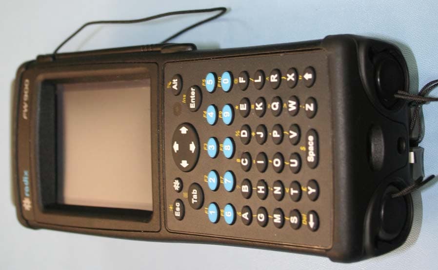
G8JHHI04
Jan 16, 2008Hand Held Interrogator
Equipment Class
TNB - Licensed Non-Broadcast Station Transmitter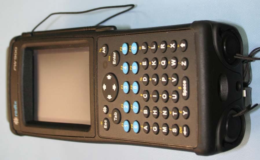
G8JHHI03
Jan 09, 2008PI900 Handheld Interrogator
Equipment Class
DSS - Part 15 Spread Spectrum Transmitter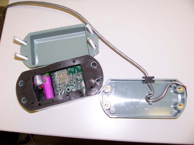
G8JEAGAS01
Dec 16, 2007EnergyAxis Gas Module
Equipment Class
DSS - Part 15 Spread Spectrum Transmitter