G8JVRT02Remote Water Meter Transponder
Elster Solutions, LLC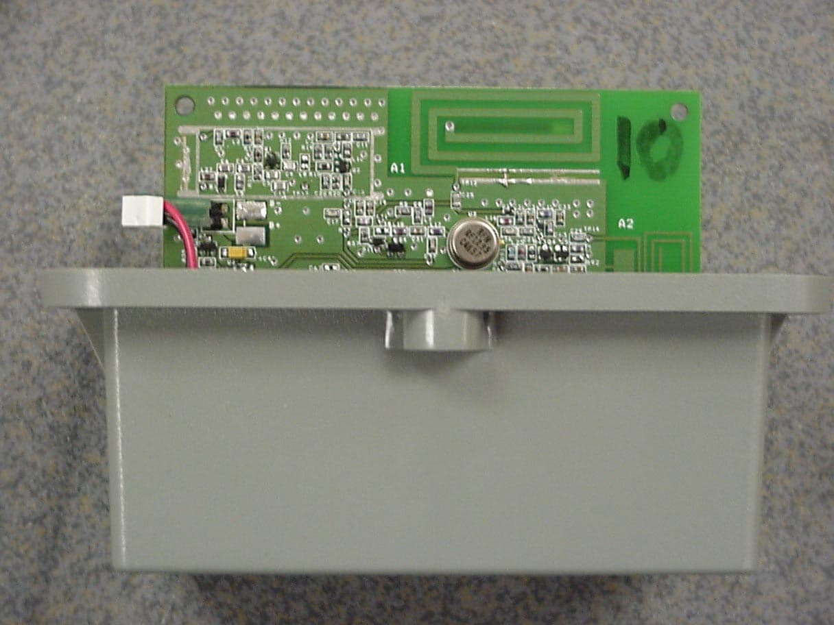
Click to zoom
Application Details
- Equipment Class
- DSC - Part 15 Security/Remote Control Transmitter
- Date of Grant
- Feb 04, 2003
- Application Purpose
- Original Equipment
- Date of Application
- Feb 04, 2003
- Equipment Note
- Remote Water Meter Transponder
- Frequency Range
- 414.50000000 - 414.50000000
- Company
- Elster Solutions, LLC
- Country
- United States
Documents & Files
Document Text
Text extracted from the exhibit documents filed with the FCC. Open a document above to read the original.
Users Manual
Rhein Tech Laboratories AMCO Automated Systems 360 Herndon Parkway Suite 1400 Remote Water Meter Transponder (RWT) FCC ID: G8JVRT02 Herndon, VA 20170 FCC Part 15.231 http://www.rheintech.com RTL WO# 2002199 Page 23 of 30 APPENDIX H: MANUAL Please see the following pages. U U U S S S E E E R R R G G G U U U I I I D D D E E E TRACE ™ V V R R T T W W a a t t e e r r T T r r a a n n s s p p o o n n d d e e r r Copyright Acknowledgements The contents of this document are the property of AMCO Automated Systems and are copyrighted. All rights reserved. Any reproduction, in whole or in part, is strictly prohibited. For additional copies of this document, please contact: AMCO Automated Systems 107 Erskine Lane Scott Depot, WV 25560 Phone 304-757-3300 Fax 304-757-3388 The information contained herein has been carefully checked and is believed to be accurate; however, no responsibility is assumed for inaccuracies. AMCO Automated Systems reserves the right to make changes without prior notice. This document is not covered by any warranty either expressed or implied. Any correction, comments or additions to the contents of this document should be directed to AMCO Automated Systems at the above address. Copyright 2002 AMCO Automated Systems. Printed in USA. TRACE, Universal RF Interface, URFI, Mini Mobile Interrogator, ReadIt and TICS are trademarks of AMCO Automated Systems. All rights reserved. MS-DOS, IBM and MicroPalm are registered trademarks of their respective owners. FCC Compliance The TRACE VRT Transponder™ has been type accepted by the Federal Communications Commission under Part 15C, low power communication device transmitter. The FCC ID for the Pit Water Transponder (PWT) is G8JVRT03, and the FCC ID for the Remote Water Transponder (RWT) is G8JVRT02. This device complies with Part 15 rules. Operation is subject to the following conditions: 1. This device may not cause harmful interference, and 2. This device must accept any interference received, including interference that may cause undesired operation. This equipment has been tested and found to comply with the limits for a Class B digital device, pursuant to part 15 of the FCC Rules. These limits are designed to provide reasonable protection against harmful interference in a residential installation. This equipment generates, uses and can radiate radio frequency energy, and if not installed and used in accordance with the instructions, may cause harmful interference to radio communications. However, there is no guarantee that interference will not occur in a particular installation. If this equipment does cause harmful interference to radio or television reception, which can be determined by turning the equipment off and on, the user is encouraged to try to correct the interference by one or more of the following measures: • Reorient or relocate the receiving antenna. • Increase the separation distance between the equipment and receiver. • Connect the equipment into an outlet on a circuit different from that to which the receiver is connected. • Consult the dealer or an experience radio/TV technician for help. Changes or modifications not expressly approved by AMCO Automated Systems could void the user’s authority to operate the equipment. TABLE OF CONTENTS VRT Transponder—User Guide Page 1 AMCO Automated Systems, January 2003 Last Saved: 1/20/2003 5:06 PM VRT Water Transponder Manual and Installation Guide Table of Contents Chapter One—Introduction................................................................................. 2 About this Document ....................................................................................... 2 Audience ................................................................................................... 2 Conventions .............................................................................................. 2 Chapter Two—Automated Meter Reading Overview........................................ 3 Basic AMR Components ................................................................................. 3 TRACE AMR System Overview ...................................................................... 4 Chapter Three—VRT Water Transponder Overview......................................... 6 VRT Water Transponder and Components..................................................... 6 How the VRT Water Transponder Works........................................................ 7 Specifications .................................................................................................. 8 Chapter Four—VRT Transponder Installation and Programming .................. 9 Installation ....................................................................................................... 9 Programming ................................................................................................... 9 Chapter Five—Troubleshooting ....................................................................... 11 INTRODUCTION VRT Transponder—User Guide Page 2 AMCO Automated Systems, January 2003 Last Saved: 1/20/2003 5:06 PM Chapter One Chapter OneChapter One Chapter One Introduction The TRACE ® VRT Transponder is the heart of AMCO Automated Systems’ portfolio of products for automated meter reading (AMR). About this Document The Transponder manual and installation Guide provides instructions for installing and troubleshooting transponders. It also includes an overview of both AMR in general and TRACE technology in particular. Audience This document is designed for utility industry meter readers and supervisory staff. In order to establish appropriate levels of detail for the material, this document assumes the following: The user is proficient in reading meters of the type currently compatible with TRACE transponders and possesses all the skills necessary to conduct meter reading by conventional means. The user has little or no prior expertise in the TRACE AMR technology. The user is familiar with common data ent…
Text truncated - open the document above for the full version.
Cover Letter(s)
American Telecommunications Certification Body Inc. 6731 Whittier Ave, McLean, VA 22101 February 3, 2003 RE: AMCO Automated Systems FCC ID: G8JVRT02 Application 1) The fundamental power appears to be miscalculated. The final value referenced in the paragraph and table should have been 62.9 from the numbers specified in the table. Since the reading is corrected by the duty cycle, then it should be compared to the average limit of 72.2 dBuV/m (Peak limit is 92.2 dBuV/m). Response : The report has been modified to show the correct limit and corrected level. 2) The readings in section 3.3 for above 1 GHz take into account a duty cycle and should therefore be compared to the average limit of 52.2 dBuV/m or alternatively 54 dBuV/m according to 15.209 (Peak limit is 72.2 dBuV/m). Please note that the average measurements provided are not considered appropriate for pulsed emissions, therefore this portion of the data will be neglected. Response : The report has been modified to show only the peak values. 3) The information provided appears to show that the TX operated over 1.5 MHz. Please explain if 15.31(m) should be applied. For example is this capable of being built or used on multiple channels, or is this strictly a tolerance. Response : The unit transmits only at one channel, and has a frequency tolerance of +.0.5, -1.0 MHz, as shown in the Specifications in the User Manual. 4) The application is being submitted for a 15.231(e), 414.5 MHz TX. The operational description explains a Quasi-TX state that covers a new frequency range of 420-451 MHz. Therefore this device may actually contains a "composite" or multi-band transmitter. Please explain the whether the Quasi-TX state is actually considered as a transmitter or not. Please provide a detailed explanation. Response : The device contains an Automatic Frequency Control (AFC) signal. These signals were considered as a spurious noise and were listed in the report. The AFC should not be considered as a second transmitter since there is no antenna connected at the end of the traces, but rather as a signal which is transmitted through traces and will radiate spurious noise. The duty cycle of the transmitter was used to correct the radiated measurement to compensate for the values by the "inherent" function of the unit. Please contact [email protected] with any questions. Thank you.
Cover Letter(s)
Rhein Tech Laboratories AMCO Automated Systems 360 Herndon Parkway Suite 1400 Remote Water Meter Transponder (RWT) FCC ID: G8JVRT02 Herndon, VA 20170 FCC Part 15.231 http://www.rheintech.com RTL WO# 2002199 Page 17 of 30 APPENDIX B: AGENCY AUTHORIZATION LETTER Please see the following page. January 16, 2003 American TCB, Inc. 6731 Whittier Avenue Suite C110 McLean, VA 22101 Re: Agent Authorization To Whom It May Concern: AMCO Automated Systems, LLC hereby authorizes Rhein Tech Laboratories, Inc. (RTL), 360 Herndon Parkway, Suite 1400, Herndon, VA 20170 to act as agent. APPLICANT ANTI-DRUG ABUSE CERTIFICATION: In signing this letter, Applicant certifies that, in the case of an individual applicant, he or she is not subject to a denial of federal benefits, that includes: FCC benefits, pursuant to Section 5301 of the Anti-Drug Abuse Act of 1988, 21 U.S.C. 853(a), or, in the case of a non-individual applicant. No party to the application is subject to a denial of federal benefits that includes FCC benefits, pursuant to that section. For the definition of a “party” for these purposes, see 47 CFR 1.2002(b). Sincerely Eric T. Kiser Director of Product Development Engineering [email protected] A A M M C C O O A A u u t t o o m m a a t t e e d d S S y y s s t t e e m m s s , , L L L L C C 107 Erskine Lane Scott Depot, WV 25560 (304) 757-3300 Fax (304) 757-3388
Cover Letter(s)
Rhein Tech Laboratories AMCO Automated Systems 360 Herndon Parkway Suite 1400 Remote Water Meter Transponder (RWT) FCC ID: G8JVRT02 Herndon, VA 20170 FCC Part 15.231 http://www.rheintech.com RTL WO# 2002199 Page 18 of 30 APPENDIX C: CONFIDENTIALITY REQUEST LETTER Please see the following page. January 16, 2003 American TCB, Inc. 6731 Whittier Avenue Suite C110 McLean, VA 22101 To Whom It May Concern: The following information is to be held confidential pursuant of 47 CFR Part 0 §0.459 and Section 552(b)(4) of the Freedom of Information Act, because the information provided contains trade secrets and is proprietary. If made public, the information might be used to the disadvantage of the applicant in the market place. • Schematics • Technical Product Description • Block Diagram Sincerely, Eric T. Kiser Director of Product Development Engineering [email protected] A A M M C C O O A A u u t t o o m m a a t t e e d d S S y y s s t t e e m m s s , , L L L L C C 107 Erskine Lane Scott Depot, WV 25560 (304) 757-3300 Fax (304) 757-3388
External Photos
Rhein Tech Laboratories AMCO Automated Systems 360 Herndon Parkway Suite 1400 Remote Water Meter Transponder (RWT) FCC ID: G8JVRT02 Herndon, VA 20170 FCC Part 15.231 http://www.rheintech.com RTL WO# 2002199 Page 26 of 30 APPENDIX J: EXTERNAL PHOTOGRAPHS PHOTOGRAPH 5: FRONT VIEW OF TRANSPONDER Rhein Tech Laboratories AMCO Automated Systems 360 Herndon Parkway Suite 1400 Remote Water Meter Transponder (RWT) FCC ID: G8JVRT02 Herndon, VA 20170 FCC Part 15.231 http://www.rheintech.com RTL WO# 2002199 Page 27 of 30 PHOTOGRAPH 6: REAR VIEW OF TRANSPONDER
ID Label/Location Info
Rhein Tech Laboratories AMCO Automated Systems 360 Herndon Parkway Suite 1400 Remote Water Meter Transponder (RWT) FCC ID: G8JVRT02 Herndon, VA 20170 FCC Part 15.231 http://www.rheintech.com RTL WO# 2002199 Page 20 of 30 APPENDIX E: LABEL AND LABEL LOCATION PHOTOGRAPH 2: LOCATION OF LABEL ON DEVICE Please refer to the following page for the label sample. 11 22 A A B B TITLE SIZE DWG NO REV SCALE SHEET OF DRAWNCHECKED QA MFG APPROVED A MCO 107 ERSKINE LANE SCOTT DEPOT, WV 25560TEL: 304 757-3300 FAX: 304 757-3388 AUTOMATED SYSTEMS, LLC MATERIAL TOLERANCES-UNLESS OTHERWISE SPECIFIEDINCHES ANGLES .X ` ` 1 ~ .XX ` .02" .XXX ` .015" SURFACES w min THIS DOCUMENT IS THE PROPERTY OF AMCO AUTOMATED SYSTEMS, ANDIT'S SUBSTANCE IS CONFIDENTIAL AND PROPRIETARY. THE CONTENTSHEREOF SHALL NOT BE PUBLISHED OR DISCLOSED TO OUTSIDE PARTIESOR USED FOR THEIR BENEFIT WITHOUT THE WRITTEN AUTHORIZATION OFAMCO AUTOMATED SYSTEMS. OLD DWG #N.A. DRAWING RELEASE ECN #: REV DESCRIPTION DATE LABEL, FCC, S/N, REMOTE, GEN 5 52870P017 1 1 B A ppenn 10/17/2002 3.500 1.500 FCC ID: G8JVRT02 AMCOAS TRACE VRT GEN 5.0 P/N 52870G500 REV. X THIS DEVICE COMPLIES WITH PART 15 OF FCC RULES. OPERATION OF THIS DEVICE IS SUBJECT TO THE FOLLOWING TWO CONDITIONS: (1) THIS DEVICE MAY NOT CAUSE HARMFUL INTERFERENCE AND (2) THIS DEVICE MUST ACCEPT ANY INTERFERENCE RECEIVED INCLUDING INTERFERENCE THAT MAY CAUSE UNDESIRED OPERATION. XXXXXXXX MATERIAL: WEATHER RESISTANT POLYIMIDE (KAPTON) or EQUIVALENT ADHESIVE: PERMANENT ACRYLIC COLORS: BLACK COPY ON WHITE BACKGROUND REVISION # PER BOM R0.125 BAR CODE AREA(DERIVED FROM S/N) TRANSPONDER SERIAL #(MIN. TEXT HEIGHT .10) SEE NOTES A INITIAL RELEASE 11/04/02 B 01/13/03 CORRECTED FCC ID
Internal Photos
Rhein Tech Laboratories AMCO Automated Systems 360 Herndon Parkway Suite 1400 Remote Water Meter Transponder (RWT) FCC ID: G8JVRT02 Herndon, VA 20170 FCC Part 15.231 http://www.rheintech.com RTL WO# 2002199 Page 28 of 30 APPENDIX K: INTERNAL PHOTOGRAPHS PHOTOGRAPH 7: FRONT VIEW OF PCB Rhein Tech Laboratories AMCO Automated Systems 360 Herndon Parkway Suite 1400 Remote Water Meter Transponder (RWT) FCC ID: G8JVRT02 Herndon, VA 20170 FCC Part 15.231 http://www.rheintech.com RTL WO# 2002199 Page 29 of 30 PHOTOGRAPH 8: BACK VIEW OF PCB Rhein Tech Laboratories AMCO Automated Systems 360 Herndon Parkway Suite 1400 Remote Water Meter Transponder (RWT) FCC ID: G8JVRT02 Herndon, VA 20170 FCC Part 15.231 http://www.rheintech.com RTL WO# 2002199 Page 30 of 30 PHOTOGRAPH 9: INSIDE VIEW
Operational Description
Rhein Tech Laboratories AMCO Automated Systems 360 Herndon Parkway Suite 1400 Remote Water Meter Transponder (RWT) FCC ID: G8JVRT02 Herndon, VA 20170 FCC Part 15.231 http://www.rheintech.com RTL WO# 2002199 Page 16 of 30 APPENDIX A: ANTENNA SPECIFICATIONS PHOTOGRAPH 1: ANTENNA LOCATION TX antenna RX antenna AMCO Automated Systems, LLC AMCO_Remote_Antenna_Specs.doc 1/27/2003 Page 1 of 1 Remote Water-Meter Transponder Antenna Specifications The Remote Water-Meter Transponder uses two (2) antennas; one for transmitting, and one for receiving. These antennas are integral to the product design. They are part of the printed wiring board. No external or purchased antennas are applicable to use with the product.
Test Report
Engineering and Testing for EMC and Safety Compliance 360 Herndon Parkway, Suite 1400 Herndon, VA 20170 Phone: 703-689-0368; Fax: 703-689-2056; Metro: 703-471-6441 CERTIFICATION APPLICATION REPORT FCC PART 15.231 Test Lab: Rhein Tech Laboratories, Inc. Phone: 703-689-0368 360 Herndon Parkway Fax: 703-689-2056 Suite 1400 Web Site: www.rheintech.com Herndon, VA 20170 E-Mail : [email protected] Applicant Information: AMCO Automated Systems Phone: 304-757-3300 Contact: Eric Kiser Fax: 304-757-3388 107 Erskine Lane E-Mail: [email protected] Scott Depot, WV 25560 FCC ID: G8JVRT02 GRANTEE FRN NUMBER: 0007856438 PLAT FORM: N/A RTL WORK ORDER NUMBER: 2002199 MODEL(S): Remote Water Meter Transponder (RWT) RTL QUOTE NUMBER: QRTL02-632 TEST REPORT DATE: December 23, 2002 American National Standard Institute: ANSI/TIA/EIA603 and ANSI/TIA/EIA 603-1 FCC Classification: Low Power Communication Device Transmitter FCC Rule Part(s): Part 15.231 Periodic operation in the band 40.66-40.70 MHz and above 70 MHz Digital Interface Information Digital Interface was found to be compliant Receiver Information Receiver was found to be compliant We, the undersigned, hereby declare that the equipment tested and referenced in this report conforms to the identified standard(s) as described in this test report. No modifications were made to the equipment during testing in order to achieve compliance with these standards. Furthermore, there was no deviation from, additions to, or exclusions from the FCC Part 2, FCC Part 15, ANSI/TIA/EIA 603, and ANSI/TIA/EIA 603-1. Signature: Date: December 23, 2002 Typed/Printed Name: Desmond A. Fraser Position: President Rhein Tech Laboratories AMCO Automated Systems 360 Herndon Parkway Suite 1400 Remote Water Meter Transponder (RWT) FCC ID: G8JVRT02 Herndon, VA 20170 FCC Part 15.231 http://www.rheintech.com RTL WO# 2002199 Page 2 of 30 TABLE OF CONTENTS 1 GENERAL INFORMATION ..................................................................................................................................................................................... 4 1.1 SCOPE .................................................................................................................................................................................. 4 1.2 TEST FACILITY .................................................................................................................................................................. 4 1.3 RELATED SUBMITTAL(S)/GRANT(S)............................................................................................................................. 4 2 TEST INFORMATION.............................................................................................................................................................................................. 5 2.1 TEST JUSTIFICATION ....................................................................................................................................................... 5 2.2 EXERCISING THE EUT ...................................................................................................................................................... 5 2.3 CONFORMITY WITH 15.231 (E) ....................................................................................................................................... 5 2.4 TEST RESULT SUMMARY ................................................................................................................................................ 7 2.5 TEST SYSTEM DETAILS ................................................................................................................................................... 8 2.6 CONFIGURATION OF TESTED SYSTEM ........................................................................................................................ 9 3 RADIATED EMISSION - §15.231.......................................................................................................................................................................... 10 3.1 RADIATED EMISSION LIMITS TEST PROCEDURE.................................................................................................... 10 3.2 DUTY CYCLE.................................................................................................................................................................... 10 3.3 RADIATED EMISSION LIMITS TEST DATA ................................................................................................................ 12 3.4 TEST EQUIPMENT USED FOR TESTING ...................................................................................................................... 12 4 MODULATED BANDWIDTH - §15.231(C)............................................................................................................................................................ 13 4.1 MODULATED BANDWIDTH TEST PROCEDURE ....................................................................................................... 13 4.2 TEST EQUIPMENT USED FOR TESTING ...................................................................................................................... 13 4.3 MODULATED BANDWIDTH TEST DATA .................................................................................................................... 13 5 CONCLUSION ....................................................................................................................................................................................................... 15 FIGURE INDEX FIGURE 1: WORST CASE CONFIGURATION OF SYSTEM UNDER TEST ................................................................................ 9 TABLE INDEX TABLE 2-1: TEST RESULT SUMMARY WITH FCC RULES AND REGULATIONS ............................................................... 7 TABLE 2-2: EQUIPMENT UNDER TEST (EUT) .......................................................................................…
Text truncated - open the document above for the full version.
Test Setup Photos
Rhein Tech Laboratories AMCO Automated Systems 360 Herndon Parkway Suite 1400 Remote Water Meter Transponder (RWT) FCC ID: G8JVRT02 Herndon, VA 20170 FCC Part 15.231 http://www.rheintech.com RTL WO# 2002199 Page 24 of 30 APPENDIX I: TEST PHOTOGRAPHS PHOTOGRAPH 3: RADIATED EMISSION FRONT VIEW, WORST CASE CONFIGURATION Rhein Tech Laboratories AMCO Automated Systems 360 Herndon Parkway Suite 1400 Remote Water Meter Transponder (RWT) FCC ID: G8JVRT02 Herndon, VA 20170 FCC Part 15.231 http://www.rheintech.com RTL WO# 2002199 Page 25 of 30 PHOTOGRAPH 4: RADIATED EMISSION REAR VIEW, WORST CASE CONFIGURATION
Contact Information
Applicant
Steve Bragg(Sr. RF Engineer)
Technical Contact
Rhein Tech LaboratoriesDesmond Fraser
[email protected]703-689-0368
360 Herndon Parkway, Suite 1400 · Herndon, Virginia · United States
Non-Technical Contact
Rhein Tech LaboratoriesKathy Grzovic
[email protected]703-689-0368
Test Firm
Tempest Inc.Louis Gnecco
Technical Specifications
| # | Rule Parts | Frequency Range | Power Output |
|---|---|---|---|
| 1 | 15.231(e) | 414.5 MHz - 414.5 MHz | - |
Other Applications from Elster Solutions, LLC
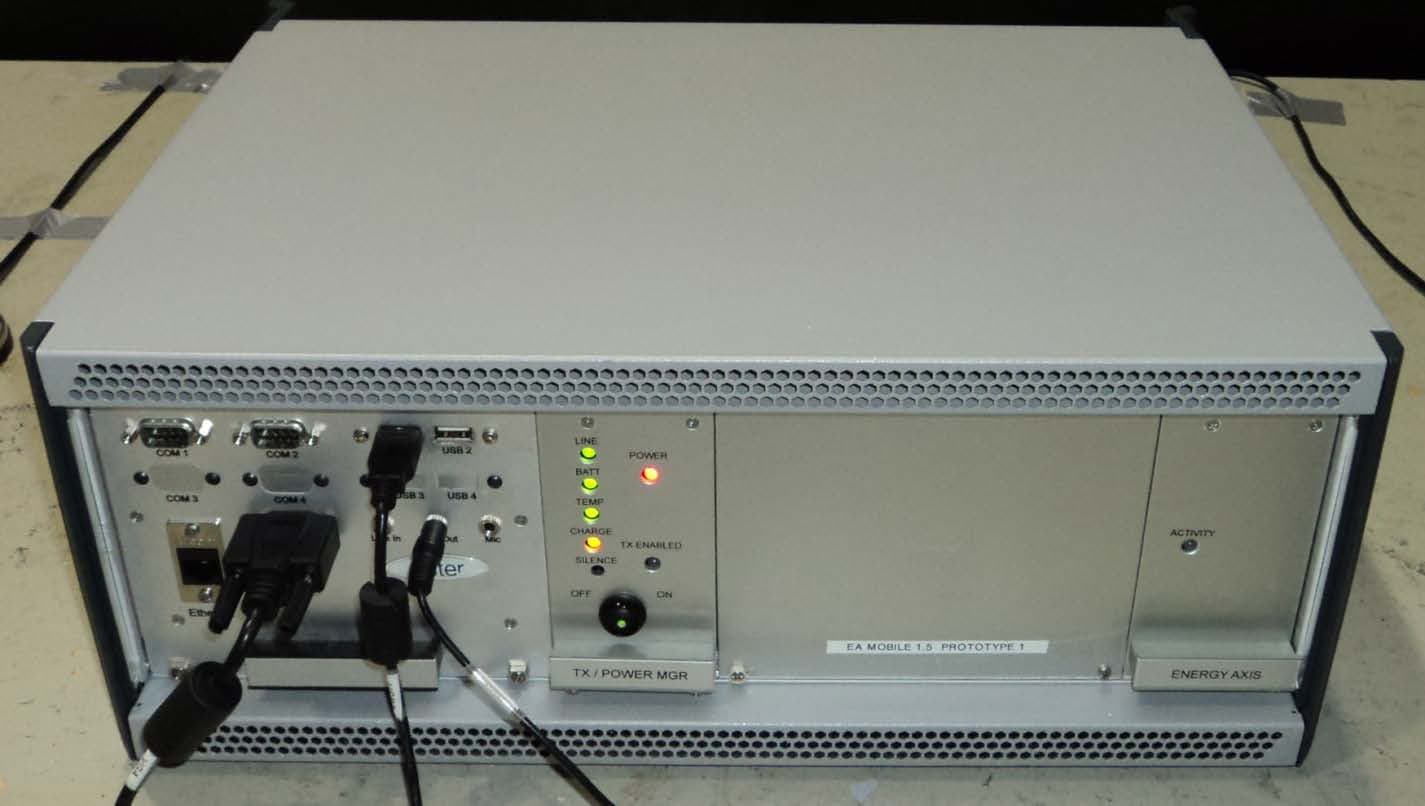
G8JEAMOBILE1
Jan 13, 2013Vehicle-Based Mobile Wireless Meter Reading Equipment
Equipment Class
TNB - Licensed Non-Broadcast Station Transmitter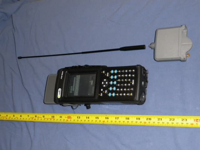
G8JHHI05
Oct 14, 2012PI900W
Equipment Class
DXX - Part 15 Low Power Communication Device Transmitter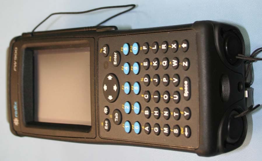
G8JHHI04
Jan 16, 2008Hand Held Interrogator
Equipment Class
TNB - Licensed Non-Broadcast Station Transmitter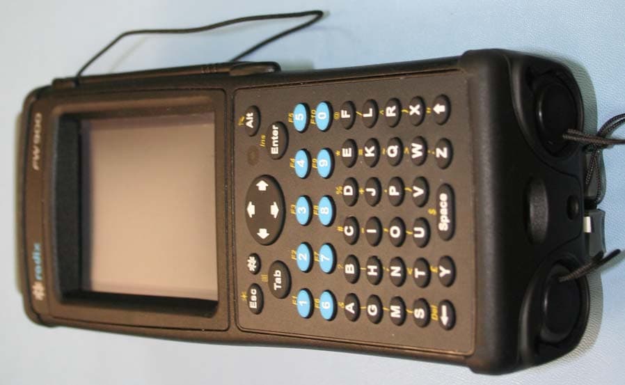
G8JHHI03
Jan 09, 2008PI900 Handheld Interrogator
Equipment Class
DSS - Part 15 Spread Spectrum Transmitter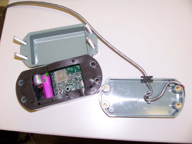
G8JEAGAS01
Dec 16, 2007EnergyAxis Gas Module
Equipment Class
DSS - Part 15 Spread Spectrum Transmitter