G9B-210192Dielectric Resonator Oscillator
Bureau D' Electronique Appliquee (B.E.A.) Inc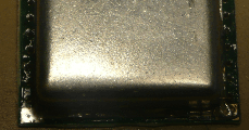
Click to zoom
Application Details
- Equipment Class
- FDS - Part 15 Field Disturbance Sensor
- Date of Grant
- Mar 11, 2012
- Application Purpose
- Original Equipment
- Date of Application
- Mar 11, 2012
- Equipment Note
- Dielectric Resonator Oscillator
- Frequency Range
- 24140.00000000 - 24140.00000000
- Country
- United States
Documents & Files
Document Text
Text extracted from the exhibit documents filed with the FCC. Open a document above to read the original.
Users Manual
Jean-Pierre LERUTH Print : 09/03/2012 Page 1 / 3 File : 4.BEA-T2 User Guide.doc B.E.A. K-Band Transceiver 21.0192 (BEA-T2) User Guide History : Date Author Version 2011/12/06 First release JPL 1.00 2012/01/19 InstructionS for OEM integrator JPL 1.01 2012/03/09 Additional instructionS for OEM integrator JPL 1.02 FCC ID : G9B-210192 IC ID : 4680A-210192 BEA Inc. (Bureau d’Electronique Appliquée) 100 Enterprise Drive, RIDC Park West Pittsburgh, PA 15275, USA Phone: (412) 249 4100 Jean-Pierre LERUTH Print : 09/03/2012 Page 2 / 3 1. Functional description of BEA-T1 Transceiver. The DRO module P/N, 21.0192 consists of a 24.150GHz Microwave Transceiver and is used in Doppler movement detectors. 2. Electrical specifications. Output frequency : Output power : 24.125 GHz ± 50 MHz < 20 dBm Type of modulation : Continuous wave ASK modulation : none Operating voltage : Regulated DC 5 V ±5% Operating current : <35mA typ. Frequency Drift vs Temperature Change : < 1 MHz / °C Operating temperature range : -30 °C to +70 °C 3. Pin arrangement. (Single row pin header) Pin I/O Description 1 Supply voltage Vcc 2 Output signal phase IF I 3 4 Ground Output signal quadrature GND IF Q Jean-Pierre LERUTH Print : 09/03/2012 Page 3 / 3 4. Regulatory Compliance • This device has been tested and approved to be compliant with Part 15 of the FCC Rules and with RSS-210 of Industry Canada. Operation is subject to the following conditions: (1) This device may not cause harmful interferences, and (2) This device must accept any interference received, including interference that may cause undesired operation. 4.1 FCC & IC Instructions • Changes or modifications made to the equipment not expressly approved by BEA Inc. may void the FCC & IC authorization to operate this equipment. • The use of the BEA-T1B transceiver is authorized into mobile or fixed devices taking into account the conditions listed below : (1) OEM Integrator may be sure that the end user manual may not contain any information about the way to install or remove the module from the final product. (2) The following information is required to be incorporated in the user manual of the final system: - This device has been tested and approved to comply with Part 15B unintentional radiator requirements - The antenna of the module may not be removed, replaced nor modified. The antenna must not be co-located or operating in conjunction with any other antenna or transmitter. No additional antenna must be used. - This device may not cause harmful interferences, and this device must accept any interference received, including interference that may cause undesired operation. (3) The module must be installed and used in strict accordance with the manufacturer’s instructions as described in the user documentation that comes with the product. (4) Power supply of the module must be conform to the electrical specifications as described in § 2 of the current user manual. (5) The antenna of the module may not be removed, replaced nor modified. The antenna must not be co-located or operating in conjunction with any other antenna or transmitter. No additional antenna must be used. (6) OEM integrator is responsible for ensuring that after the module is installed and operational into the host, it continues to be compliant with the Part 15B unintentional radiator requirements. (7) A label with the words ‘Contains FCC ID:G9B-210192’ and ‘Contains IC:4680A- 210192’ shall be applied and visible from the outside of the end product.
Cover Letter(s)
OPEN UPN5 Jean-Pierre LERUTH Print : 15/12/2011 File : 8a.BEA-T2 Confidentiality.doc Date : 06/12/2011 CONFIDENTIALITY REQUEST Federal Communication Commission Equipment Authorization Division, Application Processing Branch 7435 Oakland Mills Road Columbia, MD 21048 December, 15 2011 TO WHOM IT MAY CONCERN Pursuant to Paragraphs §0.457 and 0.459 of the Commission”s Rules (47 C.F.R.) and Section §552(b)(4) 0f the Freedom of Information Act, B.E.A. Inc. (Bureau d’Electronique Appliquée) request confidentiality for the following products FCC ID Number Product Title / Model G9B-210192 BEA Dielectric Resonator Oscillator / BEA-T2 For the product stated above, we request that the following information be held confidential: 1. Circuit diagrams, BOM, and PCBs Electronic File : ‘BEA-T2 Schematics’. 2. Block diagram Electronic File : ‘BEA-T2 Blockdiagram’. 3. Operational description Electronic File : ‘BEA-T2 Operational description’. The above exhibits contain B.E.A. Inc. trade secrets and proprietary information that could be of benefit to our competitors regarding the design of our sensors. This material is not available to the general public and we request that it be withheld form public inspection. If you have any questions, please feel free to contact me at the address shown below. Sincerely, B.E.A. Inc. Randy Wickman 100 Enterprise Drive, RIDC Park West Pittsburgh, PA 15275, USA Phone: (412) 249 4100 Email: [email protected] A HALMA COMPANY Page 1 / 1
Cover Letter(s)
Jean-Pierre LERUTH Print : 19/01/2012 Page 1 / 1 File : 9.BEA-T2 Modular Approval.doc Date : 06/12/2011 21.0192 (BEA-T2) Modular Approval Information FCC ID: G9B-210192 Requirements for equipment authorization: 1. The BEA-T2 Transceiver module working in the 24GHz frequency band has its own RF shielding. It has been designed and tested to comply with Part 15 of the Commission’s Rules without any additional shielding. 2. The BEA-T2 Transceiver module has no internal power regulation. The specifications of the power circuitry into which the module is installed are listed in the ‘installation instructions’. 3. The antenna is an integrated part of the module and cannot be removed nor replaced. 4. The BEA-T2 Transceiver module has been tested as a standalone module with power supply as specified into the datasheets. A report from a accredited laboratory is available. 5. The BEA-T2 Transceiver module has its own label and the device into which the module is installed will receive a label with the words : ‘Contains FCC ID:G9B-210192’ 6. When used in conformity with the ‘technical specification’, the BEA-T2 Transceiver module will operate in compliance with section 15.245. 7. The BEA-T2 Transceiver module complies with any other applicable RF exposure requirements.
External Photos
Jean-Pierre LERUTH Print : 19/01/2012 Page 1 / 2 File : 7.BEA-T2 Pictures.doc Date : 06/12/2011 B.E.A. Dielectric Resonator Oscillator : 21.0192 (BEA-T2) Pictures of the DRO External picture : front view External picture : rear view Jean-Pierre LERUTH Print : 19/01/2012 Page 2 / 2 Internal picture
ID Label/Location Info
Jean-Pierre LERUTH Print : 13/01/2012 Page 1 / 1 File : 5.BEA-T2 Labelling.doc Date : 13/01/2012 B.E.A. Dielectric Resonator Oscillator 21.0192 (BEA-T2) Labelling information
Internal Photos
Jean-Pierre LERUTH Print : 19/01/2012 Page 1 / 2 File : 7.BEA-T2 Pictures.doc Date : 06/12/2011 B.E.A. Dielectric Resonator Oscillator : 21.0192 (BEA-T2) Pictures of the DRO External picture : front view External picture : rear view Jean-Pierre LERUTH Print : 19/01/2012 Page 2 / 2 Internal picture
Test Setup Photos
Test report no.: 1-3880/11-01-03- 2012-03-12 Page 24 of 32 Annex A Photographs of the test setup Photo 1: Photo 2: Test report no.: 1-3880/11-01-03- 2012-03-12 Page 25 of 32 Photo 3: Photo 4: Test report no.: 1-3880/11-01-03- 2012-03-12 Page 26 of 32 Photo 5:
Contact Information
Applicant
Thomas Schluep(Vice President, Engineering)
Test Firm
cetecom advanced GmbHGerald Schmidt
Technical Specifications
| # | Rule Parts | Frequency Range | Power Output |
|---|---|---|---|
| 1 | 15.245 | 24.14 GHz - 24.14 GHz | - |
Other Applications from Bureau D' Electronique Appliquee (B.E.A.) Inc

G9B-210193
Mar 11, 2012Dielectric Resonator Oscillator
Equipment Class
FDS - Part 15 Field Disturbance Sensor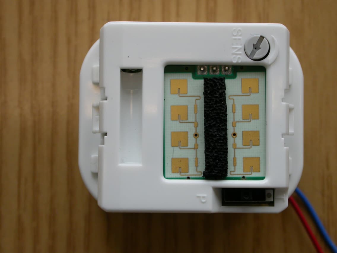
G9B-MS08
May 07, 2007Motion Detector
Equipment Class
FDS - Part 15 Field Disturbance Sensor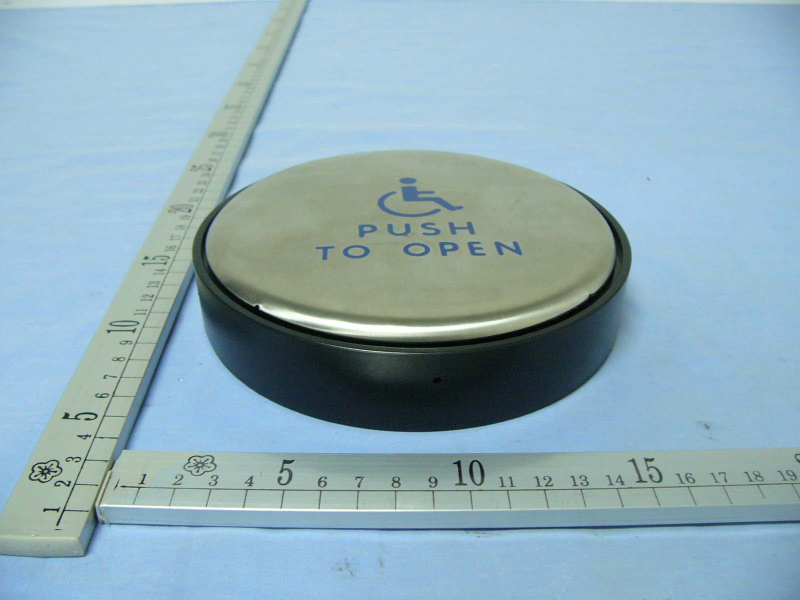
G9B-TD433PTRII
Jan 28, 2007Panther
Equipment Class
DSC - Part 15 Security/Remote Control Transmitter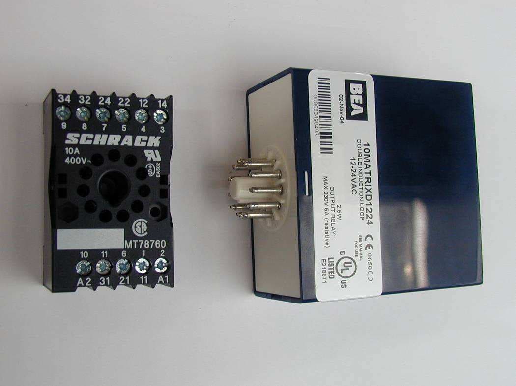
G9B-MATRIX
Sep 08, 2005Inductive Loop Sensors
Equipment Class
DCD - Part 15 Low Power Transmitter Below 1705 kHz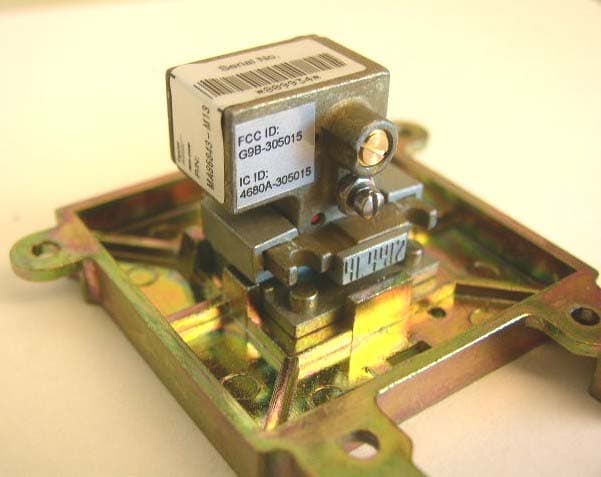
G9B-305015
Oct 24, 2004Field Disturbance Sensor
Equipment Class
FDS - Part 15 Field Disturbance Sensor