GSA-SPD2000NSSpatial Position Detector
Visonic Inc.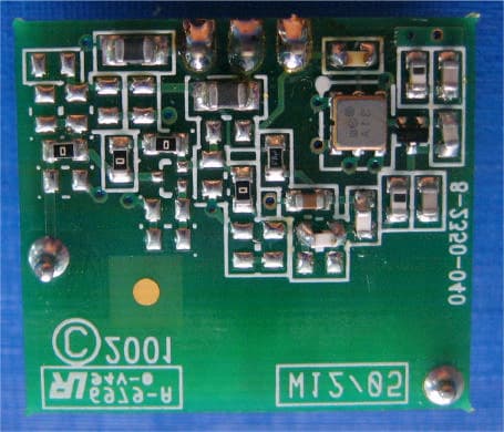
Click to zoom
Application Details
- Equipment Class
- DSC - Part 15 Security/Remote Control Transmitter
- Date of Grant
- Dec 14, 2006
- Application Purpose
- Original Equipment
- Date of Application
- Dec 14, 2006
- Equipment Note
- Spatial Position Detector
- Frequency Range
- 315.00000000 - 315.00000000
- Company
- Visonic Inc.
- Country
- United States
Documents & Files
Document Text
Text extracted from the exhibit documents filed with the FCC. Open a document above to read the original.
Users Manual
SPD-2000 NS Supervised RFID Spatial Position Detector Installation Instructions INTRODUCTION The SPD-2000 NS is a fully supervised RFID spatial position detector from Visonic Technologies (VT). The SPD-2000 NS is ideal for protecting fine art in public instutions, museums, galleries or private residences. The SPD-2000 NS detector is designed to descretly and covertly protect, location monitor and identify all types of fine art assets including paintings, statues, antiques and ceramics in environments where conventional security systems are not quite adequate. Page 1 of 3 DE3650 The SPD-2000 NS is also suitable for high-risk, stationary general asset protection; including but not limited to computers, general office and medical equipment. When deployed as part of a 'SpiderAlert' system, the SPD-2000 NS can provide on-going around-the-clock asset location monitoring in near-real time (30 second intervals). Each SPD-2000 NS detector is deployed with its own 24-bit identification code (factory set) so that each asset is protected by a uniquely numbered tag. The SPD-2000 NS contains an ultra-sensitive acceleration sensor (silicone chip mounted) that measures on two axes static (vibration) as well as dynamic (gravity) accelerations. Thus when a protected asset is moved without authorization, the SPD-2000 NS transmits a real-time identifiable coded alarm message every 30 seconds while in motion to the 'SpiderAlert' system. Each alarm transmission consists of three messages (each message @ 300ms in duration), at 700ms intervals. Thus the total duration of an alarm transmission is approximately 2300ms. The SPD-2000 NS automatically transmits an alarm restore message when the asset is again at rest or after 10 minutes has elapsed without detecting further acceleration changes so that the system can handle new alarm conditions. The SPD-2000 NS returns to generating a single supervision transmission at @ 15min. intervals for a maximum of 5 messages/hr. Each supervison transmission consists of a single message (@ 300ms in duration). Accordingly, total duration of supervision transmissions /hr is @ 1500ms. To ensure high operational reliability in security sensitive environments, the SPD-2000 NS automatically transmits supervisory status messages at 15 minute intervals or 60 minute intervals depending on the enabled mode selection position of Function Switch 2 (as detailed table 1) to the 'SpiderAlert' system throughout the day. The SPD-2000 NS is also tamper protected. Upon removing the unit's cover, the detector automatically transmits a Tamper alarm in near- real time (30 second intervals) as an alarm tracking transmission. Should the SPD-2000 NS not detect further acceleration changes after 10 minutes has elapsed, the detector returns to generating a single transmission @ every 15 minutes, comprised of three alarm messages the same as described above. The SPD-2000 NS employs a "Smart" anti-collision transmission methodogy to overcome message collisions from other RFID detectors in the protected area. Operating power is provided by single onboard commercially available 3.0 V 1/2 AA Lithium battery. When battery voltage is low, a “Low Battery” marker is added to the transmitted message. A LED illuminates upon all event transmissions (except for a low battery condition). SPD-2000 NS Advantages: • Quick and easy installation. The sensor attaches to an asset using double-sided adhesive tape or via an optional mounting bracket. • Supports four user selectable sensitivity levels for detecting unauthorized asset movement. • Powered by a single, compact 3V Lithium battery, • Small size, enables descrete, covert asset mounting. • Optional Alarm Tracking delivers near-real time (30 second intervals) location monitoring of the protected asset. SPECIFICATIONS Movement Sensitivity: 0.075g (Gravitation accel. Constant) Transmission Frequency (MHz): 315, 433.92, 447.375, 868.95, 869.025 or other frequencies according to local requirements Transmission range: Up to 60m (200 ft.) from the receiver in open indoor spaces and 30m (100 ft.) in sub-divided rooms (In environments that includes metals, the effective transmission range may drop significantly.) Overall Message Length: 36 bit pulse width modulation, including 24-bit identification code Supervision : Supervisory status messages transmitted continously at 15 minute intervals or 60 minute intervals depending on the enabled mode selection of Function Switch 2 as detailed in Table 1. Power Source: 3 V Lithium Thionyl Chloride (LiSOCl 2 ) battery, size 1/2 AA, Tadiran TL-2150, or equivalent Nominal Battery Capacity: 1 Ah Current Drain: 500 μA (STBY), 20 mA (transmission, including LED) Alarm Tracking: Automatic signaling at 30 second intervals when the protected asset is in unauthorized motion Battery Life: At least 2 years (typical operation) Battery Supervision: Automatic Low battery condition marker is automaticly added to transmitted messages Operating Temperature: 0°C to 50°C (32°F to 122°F) Dimensions (Height x Width x Depth): 72 x 49 x 18.5 mm (2-13/16 x 1-15/16 x 11/16 inches) Weight (excluding battery): 50 g (1.75 oz) Color: Black Compliance Standards: Meets FCC Part 15, ETS 300-220 and MPT1349 The 433.92 MHz models of this device comply with the European Council Directive EMC 89/336/EEC & 92/31/EEC SPD-2000 NS - Installation Instructions INSTALLATION General Information Fig. 3 (shown directly below) details how to prepare the SPD-2000 NS detector prior to mounting. 1 Remove cover 2 Install/replace battery (proper polarity) 4 ON OFF 231 Perform Function Sw. Setting (See tables 1 & 2) 3 4 Mount bracket (option) on the mounting surface, with double-sided adhesive tap or with 2 screws, and insert the assembeld detector into the bracket. 5 Press Tamper sw. once (for smooth power-up) - verify that tamper message is transmitted and LED is lit. Close cover 6 Figure 3 :Detector Preparation Process Battery Battery holder clamps Ta m p e r switch SIP Sw. Sensor car…
Text truncated - open the document above for the full version.
Block Diagram
Company Confidential SPD-2000 BLOCK DIAGRAM POWER SUPPLY MICRO CONTROLLER RF OSCILLATOR ACCELERATION SENSOR -2 AXES HARMONICS FILTER + ANTENNA MATCH ANTENNA AMPLIFIER RF AMPLIFIER 137Khz / 9.6Mhz CLOCK 1200BAUD Head office: 30 Habarzel St. Tel-Aviv 69710 Israel Tel: 972-3-7681400 Fax: 972-3-7681415 www.visonictech.com
Cover Letter(s)
30 Habarzel St., Tel Aviv, 69710, Israel Tel:+97237681400 Fax:+97237681415 www.visonictech.com October 25, 2006 American TCB 6731 Whittier Ave Suite C110 McLean, VA 22101 USA Subject: Authorization letter of Visonic Technologies Ltd. Dear Gentlemen, We the undersigned, hereby authorize Hermon Laboratories Ltd. to act on our behalf in all manners relating to application for equipment authorization, including signing of all documents relating to these matters. Any and all acts carried out by Hermon Laboratories Ltd., on our behalf shall have the same affect as acts of our own. This authorization is valid until further written notice from Visonic Technologies Ltd. Sincerely, Michael Wasserstein CEO Visonic Technologies, Ltd.
Cover Letter(s)
October 25, 2006 American TCB 6731 Whittier Ave Suite C110 McLean, VA 22101 USA Subject: Request for confidentiality for the wireless spatial position detector, model SPD-2000 NS, FCC ID:GSA-SPD2000NS Dear Gentlemen, In regards the exhibits submitted in support of the application for FCC ID:GSA- SPD2000NS, please classify the following as confidential under the provision of 47 CFR 0.459: Schematic diagram, file “schematics_16646” (2 pages of this Application). The above material contains trade secrets or technical data which Visonic Technologies Ltd. deems to be proprietary. Therefore this information would customarily be guarded from competitors and cannot be accessible to the general public. Many thanks in advance. Zachi Holtzman RF Engineer and Approvals Coordinator
Cover Letter(s)
American Telecommunications Certification Body Inc. 6731 Whittier Ave, McLean, VA 22101 November 2, 2006 RE: Visonic Technologies FCC ID: GSA-SPD2000NS I have a few comments on this Application. Depending on your responses, kindly understand there may be additional comments. 1.) It is not completely apparent from the Operational Description that this device meets the operational requirements of 15.231(a). As an example, there is no description of the transmission-on parameters when an object is moved or when the cover is removed. You are reminded that device must maintain the 5 seconds-to-off requirement for 15.231(a)(1) once triggered. You are also reminded that the “emergency condition” provisions of 15.231(a)(4) do not apply to emergencies involving property – only emergencies where life is threatened. In addition, a more complete description of how the “supervisory status” message is transmitted to show compliance with total time duration of 15.231(a)(3). Kindly provide a more comprehensive Operational Description of this device’s transmission features. 2.) Please provide an Agent Authorization letter allowing Hermon Labs to act on behalf of Visonic. 3.) If possible, please provide larger, clearer photographs of the Test Setup. The ones supplied are barely readable. William H. Graff President and Director of Engineering mailto: [email protected] The items indicated above must be submitted before processing can continue on the above referenced application. Failure to provide the requested information may result in application termination. Correspondence should be considered part of the permanent submission and may be viewed from the Internet after a Grant of Equipment Authorization is issued. Please do not respond to this correspondence using the email reply button. In order for your response to be processed expeditiously, you must submit your documents through the AmericanTCB.com website. Also, please note that partial responses increase processing time and should not be submitted. Any questions about the content of this correspondence should be directed to the sender.
Cover Letter(s)
FCC ID: GSA-SPD2000NS In reply to e-mail dated November 2, 2006 Dear Mr. Graff, Below is the answers to your questions. 1. Please refer to “SPD2000_Operational description_rev1” uploaded via “Operational description” folder, “SPD2000 Guide - DE3650_V11” uploaded via “User guide” folder, “VISRAD_FCC.16646_rev1” test report uploaded via “Test report” folder. The detector transmits continuously with 30 s intervals only during alarm condition (movement or tamper alarm) qualified as emergencies involving security; therefore the “emergency condition” provisions of 15.231(a)(4) may be applied. Please review. 2. Please refer to “Authorization Letter_Visonic” uploaded via “Additional information” folder. 3. Unfortunately, we have no test setup photos of better quality. With great respect, Natasha
Cover Letter(s)
American Telecommunications Certification Body Inc. 6731 Whittier Ave, McLean, VA 22101 November 25, 2006 RE: Visonic Technologies, Ltd. FCC ID: GSA-SPD2000NS After a review of the submitted information, I have a few comments on the above referenced Application. 1) Measurements below 1 GHz should be done on a approved OAT’s or similar site. Test photographs appear to suggest this was only done in a anechoic facility. Please review. 2) Can you explain the following from the operational description : "Thus when a protected asset is moved without authorization , ........." Can you explain how the device/tag understands it is moved with authorization? This will help to define an "alarm condition" rather than simply transmitting every time it is moved. Timothy R. Johnson Examining Engineer mailto: [email protected] The items indicated above must be submitted before processing can continue on the above referenced application. Failure to provide the requested information may result in application termination. Correspondence should be considered part of the permanent submission and may be viewed from the Internet after a Grant of Equipment Authorization is issued. Please do not respond to this correspondence using the email reply button. In order for your response to be processed expeditiously, you must submit your documents through the AmericanTCB.com website. Also, please note that partial responses increase processing time and should not be submitted. Any questions about the content of this correspondence should be directed to the sender.
Cover Letter(s)
FCC ID: GSA-SPD2000NS In reply to e-mail dated December 4, 2006 Dear Mr. Johnson, Below is the answer to your question. We had no photographs from OATS and to be sure have repeated these tests again at the OATS. The results are quite similar to the previous ones and provided in the new revision of the test report. Please refer to “VISRAD_FCC.16646_rev2” test report (Section 7.2, Table 7.2.3) uploaded via “Test report” folder and “Setup_photos_16646_rev1” uploaded via “Test setup photos” folder 12/14/2006. With great respect, Natasha
Cover Letter(s)
Inquiry: Regarding 15.231(a)(4) which cites: 15.231(a)(4) Intentional radiators which are employed for radio control purposes during emer gencies involving fire, security, and safety of life, when activated to signal an alarm, may operate during the pendency of the alarm condition Can security as given above be understood to also apply to asset management situations such as for the following 2 conditions were a device is attached to : 1) Tamper - If the units cover is removed the detectorautomatically transmits a Tamper alarm in near-real time (30 second intervals) as an alarm tracking transmission. 2) Thus when a protected asset is moved without authorization, the device transmits a real- time identifiable coded alarm message. The real-time means that such a transmission is repeated every 30 s while in motion. It would seem that both situations would be deemed an alarm condition associated with security of any asset the device is attached to. However we would like the FCC to review and comment. Note the following is a more complete description of the device in question: The device is ideal for protecting fine art in public instutions, museums, galleries or private residences. It is designed to descretly and covertly protect, location monitor and identify all types of fine art assets including paintings, statues, antiques and ceramics in environments where conventional security systems are not quite adequate. It is also suitable for high-risk, stationary general asset protection; including but not limited to computers, general office and medical equipment. Response: We agree that the tamper alarm is considered as a normal alarm situation as described in Section 15.231(a)(4), as therefore would be acceptable for approval under this section. Do not reply to this message. ! Please select the Reply to an Inquiry Response link from the OET Inquiry System to add any additional information pertaining to this inquiry. From: Generic Office of Engineering Technology <[email protected]> Subject: Response to Inquiry to FCC (Tracking Number 171179) To: [email protected] Page 1 of 1In 12/4/2006Printed for "Timothy R. Johnson" <[email protected]>
External Photos
FCC ID:GSA-SPD2000NS Date: February 2006 Page 1 of 3 EXTERNAL PHOTOGRAPHS This document contains 2 photographs FCC ID:GSA-SPD2000NS Date: February 2006 Page 2 of 3 Photograph No.1 Wireless Spatial Position Detector Front view FCC ID:GSA-SPD2000NS Date: February 2006 Page 3 of 3 Photograph No.2 Wireless Spatial Position Detector Rear view
Internal Photos
FCC ID:GSA-SPD2000NS Date: February 2006 Page 1 of 9 INTERNAL PHOTOGRAPHS This document contains 8 photographs FCC ID:GSA-SPD2000NS Date: February 2006 Page 2 of 9 Photograph No.1 Wireless Spatial Position Detector Internal view FCC ID:GSA-SPD2000NS Date: February 2006 Page 3 of 9 Photograph No.2 Wireless Spatial Position Detector Component side of the main PCB with RF PCB FCC ID:GSA-SPD2000NS Date: February 2006 Page 4 of 9 Photograph No.3 Wireless Spatial Position Detector Print side of the main PCB with RF PCB FCC ID:GSA-SPD2000NS Date: February 2006 Page 5 of 9 Photograph No.4 Wireless Spatial Position Detector Side view of the main PCB and RF PCB with antenna assembly FCC ID:GSA-SPD2000NS Date: February 2006 Page 6 of 9 Photograph No.5 Wireless Spatial Position Detector Component side of the main PCB without RF PCB FCC ID:GSA-SPD2000NS Date: February 2006 Page 7 of 9 Photograph No.6 Wireless Spatial Position Detector Print side of the main PCB without RF PCB FCC ID:GSA-SPD2000NS Date: February 2006 Page 8 of 9 Photograph No.7 Wireless Spatial Position Detector Component side of the RF PCB FCC ID:GSA-SPD2000NS Date: February 2006 Page 9 of 9 Photograph No.8 Wireless Spatial Position Detector Print side of the RF PCB
Operational Description
SPD-2000 NS Operational Description The SPD-2000 NS contains an ultra-sensitive acceleration sensor (silicone chip mounted) that measures on two axes static (vibration) as well as dynamic (gravity) accelerations. Thus when a protected asset is moved without authorization, the SPD-2000 NS transmits a real-time identifiable coded alarm message to the 'SpiderAlert' system. The alarm transmission is three messages of about 300 ms each with about 700 ms intervals from each other. The total duration of the alarm transmission is about 2300 ms. The real-time means that such a transmission is repeated every 30 s while in motion. The SPD-2000 NS automatically transmits an alarm restore message when the asset is again at rest or after 10 minutes has elapsed without detecting further acceleration changes so that the system can handle new alarm conditions. The SPD-2000 NS returns to generating a single supervision transmission at about 15 minute intervals to ensure high operational reliability in security sensitive environments. The supervision transmission is one message of about 300 ms long. The maximum number of the supervision transmissions in one hour is five, therefore approximately duration of supervision transmissions per hour is 1500 ms. The SPD-2000 NS is also tamper protected. Upon removing the unit's cover, the detector automatically transmits a Tamper alarm in near-real time (30 second intervals) as an alarm tracking transmission. Should the SPD-2000 NS not detect further acceleration changes after 10 minutes has elapsed, the detector returns to generating a single transmission at about 15 minute intervals, comprised of three alarm messages the same as the alarm transmissions described above. Operating power is provided by single onboard commercially available 3.0 V 1/2 AA Lithium battery. When battery voltage is low, a “Low Battery” marker is added to the transmitted message. A LED illuminates upon all event transmissions (except for a low battery condition). Radio characteristics: The transmitter is a resonator based oscillator with an RF output amplifier. The output power is less than 0dbm. The DC voltage for the final radio section is 3V and can decrease to 2.5V. The current at the last radio stage is 80mA at transmission and can decrease to 70mA.
Test Report
Hermon Laboratories Ltd. P.O.Box 23, Binyamina 30500, Israel Tel. +972 4628 8001 Fax. +972 4628 8277 E-mail: [email protected] Page 1 of 47 Report ID: VISRAD_FCC.16646_rev2.doc Date of Issue: 12/14/2006 Electrical TEST REPORT ACCORDING TO: FCC CFR 47 PART 15 Subpart C, section 15.231(a) FOR: Visonic Technologies Ltd. Wireless Spatial Position Detector Model: SPD-2000 NS 315 MHz This report is in conformity with ISO/ IEC 17025. The A2LA logo endorsement applies only to the test methods and the standards that are listed in the scope of Hermon Laboratories accreditation. The test results relate only to the items tested. This test report shall not be reproduced in any form except in full with the written approval of Hermon Laboratories Ltd. Report ID: VISRAD_FCC.16646_rev2.doc Date of Issue: 12/14/2006 Page 2 of 47 Table of contents 1 Applicant information..................................................................................................................................................... 3 2 Equipment under test attributes .................................................................................................................................... 3 3 Manufacturer information .............................................................................................................................................. 3 4 Test details.................................................................................................................................................................... 3 5 Tests summary.............................................................................................................................................................. 4 6 EUT description............................................................................................................................................................. 5 6.1 General information....................................................................................................................................................... 5 6.2 Changes made in the EUT ............................................................................................................................................ 5 6.3 Test configuration.......................................................................................................................................................... 5 6.4 EUT general view .......................................................................................................................................................... 5 7 Transmitter tests according to 47CFR part 15 subpart C requirements ........................................................................ 6 7.1 Periodic operation requirements ................................................................................................................................... 6 7.2 Field strength of emissions.......................................................................................................................................... 12 7.3 Occupied bandwidth test ............................................................................................................................................. 28 7.4 Antenna requirements ................................................................................................................................................. 30 7.5 Radiated emission measurements .............................................................................................................................. 31 8 APPENDIX A Test equipment and ancillaries used for tests....................................................................................... 35 9 APPENDIX B Measurement uncertainties................................................................................................................... 36 10 APPENDIX C Test facility description ......................................................................................................................... 37 11 APPENDIX D Specification references ....................................................................................................................... 37 12 APPENDIX E Abbreviations and acronyms................................................................................................................. 38 13 APPENDIX F Test equipment correction factors ......................................................................................................... 39 Report ID: VISRAD_FCC.16646_rev2.doc Date of Issue: 12/14/2006 Page 3 of 47 1 Applicant information Client name: Visonic Technologies Ltd. Address: Habarzel street 30, Tel Aviv, Israel, 69710 Telephone: +972 3645 6714 Fax: +972 3645 6788 E-mail: [email protected] Contact name: Mr. Arick Elshtein 2 Equipment under test attributes Product name: Wireless Spatial Position Detector Product type: Transmitter Model: SPD-2000 NS Operating frequency: 315 MHz Receipt date: 8/24/2005 3 Manufacturer information Manufacturer name: Visonic Technologies Ltd. Address: Habarzel street 30, Tel Aviv, Israel, 69710 Telephone: +972 3645 6714 Fax: +972 3645 6788 E-Mail: [email protected] Contact name: Mr. Arick Elshtein 4 Test details Project ID: 16646 Location: Hermon Laboratories Ltd. P.O.Box 23, Binyamina 30500, Israel Test started: 8/24/2005 Test completed: 12/13/2006 Test specifications: FCC Part 15, subpart C, ß15.231(a); subpart B, ß15.109 Report ID: VISRAD_FCC.16646_rev2.doc Date of Issue: 12/14/2006 Page 4 of 47 5 Tests summary Test Status Transmitter characteristics Section 15.231(a), Periodic operation requirements Pass Section 15.231(b), Field strength of emissions Pass Section 15.231(c), Occupied bandwidth Pass Section 15.207(a), Conducted emission Not required Section 15.203, Antenna requirement Pass Unintentional emissions Section 15.107, Conducted emission at AC power port Not required Section 15.109, Radiated emission, Class B P…
Text truncated - open the document above for the full version.
Test Setup Photos
FCC ID:GSA-SPD2000NS Date: December 2006 Page 1 of 9 SETUP PHOTOGRAPHS This document contains 8 photographs FCC ID:GSA-SPD2000NS Date: December 2006 Page 2 of 9 Photograph No.1 Setup for spurious emission field strength measurements in anechoic chamber below 30 MHz FCC ID:GSA-SPD2000NS Date: December 2006 Page 3 of 9 Photograph No.2 Setup for spurious emission field strength measurements in anechoic chamber from 30 to 1000 MHz FCC ID:GSA-SPD2000NS Date: December 2006 Page 4 of 9 Photograph No.3 Setup for spurious emission field strength measurements at OATS from 200 to 1000 MHz FCC ID:GSA-SPD2000NS Date: December 2006 Page 5 of 9 Photograph No.4 Setup for spurious emission field strength measurements in anechoic chamber above 1000 MHz FCC ID:GSA-SPD2000NS Date: December 2006 Page 6 of 9 Photograph No.5 Setup for spurious emission field strength measurements at OATS above 1000 MHz FCC ID:GSA-SPD2000NS Date: December 2006 Page 7 of 9 Photograph No.6 Setup for occupied bandwidth test FCC ID:GSA-SPD2000NS Date: December 2006 Page 8 of 9 Photograph No.7 Setup for unintentional radiated emission measurements in anechoic chamber FCC ID:GSA-SPD2000NS Date: December 2006 Page 9 of 9 Photograph No.8 Setup for radiated emission measurements in anechoic chamber, EUT view
Contact Information
Applicant
Scott Jensen(Tec Manager)
860-243-0833
Technical Contact
Hermon LaboratoriesAlex Usoskin
[email protected]972-4628-8001
Harakevet Industrial zone · Binyamina · Israel
Non-Technical Contact
Visonic Technologies Ltd.Zachi Holzman
[email protected]972 3768 1408
Test Firm
Hermon Laboratories Ltd.Alexander Usoskin
Technical Specifications
| # | Rule Parts | Frequency Range | Power Output |
|---|---|---|---|
| 1 | 15.231 | 315 MHz - 315 MHz | - |
Other Applications from Visonic Inc.

GSA5-BTC00433
Nov 14, 2007Infant Protection Bracelet
Equipment Class
DSC - Part 15 Security/Remote Control Transmitter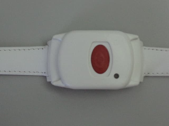
GSAWPK250
Jun 03, 2007PANIC WATCH
Equipment Class
DSC - Part 15 Security/Remote Control Transmitter
GSA5-RLE00125B
May 28, 2007LF Exciter
Equipment Class
DCD - Part 15 Low Power Transmitter Below 1705 kHz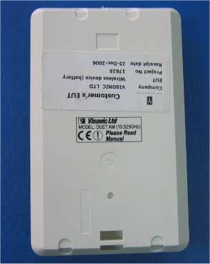
GSADUETAM
May 16, 2007Dual-Technology Microwave/PIR Intrusion Detector
Equipment Class
FDS - Part 15 Field Disturbance Sensor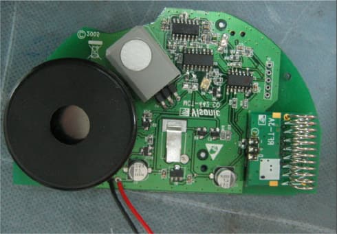
GSAMCT442
May 01, 2007Supervised Indoor Wireless CO Gas Detector
Equipment Class
DSC - Part 15 Security/Remote Control Transmitter