GSA5-BTC00433Infant Protection Bracelet
Visonic Inc.
Click to zoom
Application Details
- Equipment Class
- DSC - Part 15 Security/Remote Control Transmitter
- Date of Grant
- Nov 14, 2007
- Application Purpose
- Original Equipment
- Date of Application
- Nov 14, 2007
- Equipment Note
- Infant Protection Bracelet
- Frequency Range
- 433.92000000 - 433.92000000
- Company
- Visonic Inc.
- Country
- United States
Documents & Files
Document Text
Text extracted from the exhibit documents filed with the FCC. Open a document above to read the original.
Users Manual
Infant Protection Bracelet User Guide Part Numbers: 5-BTC00433-A, 5-BTC00433 Elpas Active RFID Solutions Page 1 of 4 BTC03U01 General Overview The Elpas Infant Protection Bracelet from Visonic Technologies (VT) is a rechargeable miniature, unified active long-range Radio Frequency (RFID) and Infrared device. The bracelet provides 24/7 infant protection by tracking the real-time location of newborns in maternity wards and by generating mother-baby mismatch alarms. The Infant Protection Bracelet is comprised of a rechargeable tag and a di sposable, anti-tamper, adjustable band made of skin-safe non-latex materials that can be retightened should the baby loose weight. When worn by the newborn, the bracelet automatically transmits removal alert notifications for keeping facility personnel informed of deliberate or accidental tampering and/or removal of the baby from the protected area. The bracelet’s all-in-one, dual technology transmitter continuously emits low power, beacon type radio frequency (RF) messages as well as safe, supplemental infra-red (IR) messages that identifies the exact real-time location of the new born infant This same RF/IR technologies also continuously broadcasts the operational st atus of the tag (such as whether the tag is moving or at rest, it’s battery state and the condition of its tamper wire). The bracelet's onboard magnetic low frequency (LF) receiver adds chokepoint area detection so whenever the new born infant nears a prohibited exit/entrance covered by an Elpas LF Exciter a security intervention alarm is raised. Made of tough ABS thermoplastic, the Elpas Infa nt Protection Bracelet is shower and bath proof as well as temperature stable. Small in size and weight (39.4mm long, 31.5mm wide and 14.8mm thick) is rechargeab le and includes LED visual indicators that illuminate whenever the bracelet transmits and/or when a low battery condition exists. CAUTION: It is important that you read, understand, and follow the instructions in this document. If you have questions, call your local Visonic Technologies support representative. This document is intended for trained system integrators, field service or maintenance engineers that need to troubleshoot problems in the EIRIS system, or configurations and processes. Tamper Transmissions Transmission Rate: Single burst of 4 IR/RF transmissions (eac h lasting @ 2ms) and the total burst time not exceeding 1 second. Event Transmission Rates in LF Zones Moving Bracelet LF Response Time: Onboard LF receiver activates every 0.6 seconds to check if the tag is in a LF zone. Transmission Rate: Continuous bursts of 4 messages (each lasting @ 2ms), with intervals of 400ms. Transmitted Message Type: IR/RF Data Message includes ID code of LF Exciter. Motionless Bracelet LF Response Time: Onboard LF receiver activates every 15 seconds to check if the tag is in a LF zone. Transmission Rate when in LF : Continuous bursts of 4 messages (each lasting @ 2ms), with intervals of 400ms. Transmitted Message Type : IR/RF Data Message includes ID code of LF Exciter. Comments on IR Signaling Attaining the maximum IR reception range depends mainly on direct line of sight between the transmitter and the receiver. Nevertheless, certain environments allow the signal to reach the receiver in a roundabout path, by reflection or refraction of the infrared radi ation. Tiled floors (uncarpeted), walls, smooth ceilings (not too high) can reflect IR signals reasonably well, and allowing them to be received even when the radiating source is pointed away from the receiver. Wi th good indirect reflection path, a range of 5 - 6m (15 - 18ft) is expected (with poor reflection, the range gets even shorter). The user is therefore strongly advised to point the transmitter directly at the nearest re ceiver or, if the location of the nearest receiver is unknown, to press the transmit button several times wh ile pointing the transmitte r in different directions. It is strongly recommended not install IR receiver ou tdoors, facing direct sunl ight, or near fluorescent lamps, to prevent interference to IR reception. The installer is encouraged to test the reception ra nge in the various zones and to install additional receivers if necessary. Comments on Radio Signaling Some limitations have to be considered. A. Receivers may be blocked by radio signals occurring on or near their operating frequencies, regardless of the code selected. B. A receiver can only respond to one transmitted signal at a time. C. Wireless equipment should be tested regularly (at least once a week) to determine if there are sources of interference and to protect against faults. Infant Protection Bracelet – User Guide ________________________________________________________________________________________ ___ Page 2 of 4 BTC03U01 Preparing the Bracelet for Usage 1. Hold the tag with the back side face down in one hand, and the disposable tamper band in the other. 2. Place the snap-on cap on the tag. Make sure to match the wide edge of the cap to the wide edge of the tag. Then verify that the tag is active. Attaching the Bracelet 1. Place the bracelet around th e baby’s ankle such that the cap part of the disposable tamper band is always on top. 2. Using the grip key, adjust the band length as needed to obtain a snug fit around the baby's ankle. Then remove the grip ke y by turning it counter- clockwise 3. Finally position the bracelet on the baby's ankle as shown here Removing the Bracelet 1. Using baby-safe scissors cut one of the two tamper wires (around the ankle) as close as possible to the tag. NOTE: It is highly recommended to perform a match test between the Mother tag and Infant Protection Bracelet before removing the bracelet and releasing the mother with the baby (Refer to the Nurse Station BabyMatch III Users Guide for more information). Removing the Disposable Tamper Band 2. Push the tag gently through the Extractor Tool until it clicks into place. 3. Press on the cap and release the…
Text truncated - open the document above for the full version.
Block Diagram
Company Confidential BTC BLOCK DIAGRAM POWER SUPPLY MICRO CONTROLLER RF OSCILLATOR INDUCTORS -2 AXES ANTENNA MATCH LOOP ANTENNA LF RECEIVER 13.56MHZ CRYSTAL 3.64Mhz CLOCK 19200BAUD IR TX DATA 455KHZ MOTION SENSOR Head office: 30 Habarzel St. Tel-Aviv 69710 Israel Tel: 972-3-7681400 Fax: 972-3-7681415 www.visonictech.com
Cover Letter(s)
20 September, 2007 ATCB 6731 Whittier Avenue Suite C110 McLean, VA 22101 To whom it may concern, I authorize Arik Elshtein of Visonic Ltd. (corporate HQ) to sign for all FCC and IC matters. Sincerely, Scott B. Jensen, CPP Technical Manager Ext. 217 65 West Dudley Town Road Bloomfield, CT 06002-1376 Tel: (860) 243-0833, (800) 223-0020 Fax: (860) 242-8094 Email: [email protected]
Cover Letter(s)
September 6, 2007 American TCB 6731 Whittier Ave Suite C110 McLean, VA 22101 USA Subject: Request for confidentiality for the Baby Tag, model 5-BTC00433-A, FCC ID:GSA5-BTC00433 Dear Gentlemen, In regards the exhibits submitted in support of the application for FCC ID:GSA5-BTC00433, please classify the following as confidential under the provision of 47 CFR 0.459: 1) Schematic diagram, file “BTC_schematics” (4 pages of this Application). 2) Operational description (2 pages of this Application). The above material contains trade secrets or technical data which Visonic Inc. deems to be proprietary. Therefore this information would customarily be guarded from competitors and cannot be accessible to the general public. Many thanks in advance. Arick Elshtein, International Standards Department Manager
Cover Letter(s)
30 Habarzel St. Tel-Aviv 69710 Israel Tel: 972-3-7681400 Fax: 972-3-7681415 www.visonictech.com September 30, 2007 American TCB 6731 Whittier Ave Suite C110 McLean, VA 22101 USA Subject: Authorization letter of Visonic Ltd. Dear Gentlemen, We the undersigned, hereby authorize Hermon Laboratories Ltd. to act on our behalf in all manners relating to application for equipment authorization, including signing of all documents relating to these matters. Any and all acts carried out by Hermon Laboratories Ltd., on our behalf shall have the same affect as acts of our own. This authorization is valid until further written notice from Visonic Technologies. Arick Elshtein, International Standards Department Manager
Cover Letter(s)
American Telecommunications Certification Body Inc. 6731 Whittier Ave, McLean, VA 22101 September 18, 2007 RE: Visonic Inc. FCC ID: GSA5-BTC00433 After a review of the submitted information, I have a few comments on the above referenced Application. Depending on your responses, kindly understand there may be additional comments. 1) Due to various concerns recently seen about proper authority being given to others for FCC and/or IC matters, the agency letter (and ideally confidentiality letters as well) should be signed by someone traceable to have the proper authority. For instance, the FCC site shows Scott Jensen as the correct contact of authority for FCC matters. Therefore the agency letters should be signed by this contact or alternatively a letter showing who he has “deputized” (i.e. Michael Wasserstein) to sign on his behalf may be provided as well. 2) FYI....The device does not appear to be subject to DoC requirements under 15.101 and therefore should not be labeled as such. For instance, the device does not appear to be a PC peripheral and the RX portion of the device is outside 30 – 960 MHz range regulated by Part 15. 3) Page 3 of the users manual cites motion RF transmissions are every 7.5 sec. This is less that the minimum measured and allowed in 15.231 (10 sec. min. and/or 30* duration of transmission). 4) The information presented in Table 7.1.2 appears to be for motionless RF transmissions (manual says these are approx. 2 msec in duration). How about the motion transmissions. The manual cites these are 400 msec. Please provide appropriate test data for this condition. 5) 400 msec transmit duration would also affect duty cycle correction factor. Please adjust. Note that compliance may be affected depending on the worse case results of the duty factor. 6) Tamper conditions shows transmissions beyond the 1 second (1.412 second duration for the series of transmissions. 7) Please explain why the fundamental in plot 7.2.3 appears higher than reported anywhere else – including the data tables. Timothy R. Johnson Examining Engineer mailto: [email protected] The items indicated above must be submitted before processing can continue on the above referenced application. Failure to provide the requested information may result in application termination. Correspondence should be considered part of the permanent submission and may be viewed from the Internet after a Grant of Equipment Authorization is issued. Please do not respond to this correspondence using the email reply button. In order for your response to be processed expeditiously, you must submit your documents through the AmericanTCB.com website. Also, please note that partial responses increase processing time and should not be submitted. Any questions about the content of this correspondence should be directed to the sender.
Cover Letter(s)
American Telecommunications Certification Body Inc. 6731 Whittier Ave, McLean, VA 22101 October 17, 2007 RE: Visonic Inc. FCC ID: GSA5-BTC00433 After a review of the submitted information, I have a few comments on the above referenced Application. Depending on your responses, kindly understand there may be additional comments. 1) Much of the TX information in the manual was adjusted from 400 msec duration to 400 msec intervals with 4 transmissions. Also, previous comment regarding tamper conditions shows transmissions beyond the 1 second (1.412 second duration for the series of transmissions. Previously it appears that only tamper TX would last 1.412 sec, but now with revised manual all transmissions appears to follow this. Note that the FCC requirement is maximum of 1 second period to meet 15.231(e) transmissions. Additionally, the users manual was adjusted to show in motion and motionless also transmit at this duty cycle. To meet FCC requirements, it would appear that a maximum of 3 transmissions may occur. Currently the device does not appear to meet 15.231(e) requirements Timothy R. Johnson Examining Engineer mailto: [email protected] The items indicated above must be submitted before processing can continue on the above referenced application. Failure to provide the requested information may result in application termination. Correspondence should be considered part of the permanent submission and may be viewed from the Internet after a Grant of Equipment Authorization is issued. Please do not respond to this correspondence using the email reply button. In order for your response to be processed expeditiously, you must submit your documents through the AmericanTCB.com website. Also, please note that partial responses increase processing time and should not be submitted. Any questions about the content of this correspondence should be directed to the sender.
Cover Letter(s)
FCC ID: GSA5-BTC00433 In reply to e-mail dated September 18, 2007 Dear Mr. Johnson, Below is the answers to your questions. 1. Please refer to “FCC_authority_letter” uploaded via “Additional information” folder and to “Authorization_letter FOR VT” uploaded via “Additional information” folder. 2. Please refer to “Label_location_16642_rev1” uploaded via “Label location” folder. 3. According to our customer’s statement, the rate that appeared in the users manual was in error. Please refer to “Infant Protection Bracelet User Guide_V8_16642” uploaded via “Users Manual” folder with correct, 15 second, transmission rate for RF. 4. According to our customer’s statement, again the users manual was inaccurate. The RF transmission is the same in motion and motionless states. The transmission rate is always approximately 2 ms in length. Please refer to “Infant Protection Bracelet User Guide_V8_16642” uploaded via “Users Manual” folder. 5. According to our customer’s statement, again the users manual was incorrect. 400 ms is the interval of the burst during an event and not the message length. Please refer to “Infant Protection Bracelet User Guide_V8_16642” uploaded via “Users Manual” folder. 6. When a tag is tampered, it sends a single transmission burst consisting of four pulses with 400 ms intervals, the total length of transmission is 1.412 s. 7. Plot 7.2.3 shows the prescan results obtained in the semi anechoic chamber. This plot is intended to demonstrate that there are no emissions other than carrier and second harmonic in 30 – 1000 MHz range. The fundamental emission exceeds the reference level and the measurement accuracy cannot be guaranteed. The reference level was adjusted to obtain sufficient margin of the internal noise and limit. The final measurements were performed at the OATS including the full maximization of emission. The actual difference obtained between sites is 69.93 dBuV/m versus 73.2 dBuV/m or 3.27 dB. Taking into account the above considerations and uncertainty of RE measurements – it really can happen. With great respect, Natasha
Cover Letter(s)
FCC ID: GSA5-BTC00433 In reply to e-mail dated October 17, 2007 Dear Mr. Johnson, Below are the answers to your questions. 1) There are the types of transmissions generated by BTC: supervision, alarm and tamper. All transmissions have the same length of transmission message 2ms approx. The supervision transmission consists of one transmission of 2ms approx. The interval between two supervision transmissions is approx. 15s and complies with FCC Part 15, subpart C, §15.231(e). The alarm and tamper transmissions consist of four 2ms transmissions with 400ms intervals between them, the total duration is approx. 1.4s and complies with FCC Part 15, subpart C, §15.231(a). Please refer to “Infant Protection Bracelet User Guide_V11_16642” uploaded via “Users Manual” folder, “BTC Operational Description_rev3_16642” uploaded via “Operational Description” folder with corrected transmissions description, as well as to the test report “VISRAD_FCC.16642_rev2” uploaded via “Test Report” folder with revised Section 7.1. With great respect, Natasha
External Photos
FCC ID:GSA5-BTC00433 Date: October 2006 Page 1 of 5 EXTERNAL PHOTOGRAPHS This document contains 4 photographs FCC ID:GSA5-BTC00433 Date: October 2006 Page 2 of 5 Photograph No.1 Baby Tag General view FCC ID:GSA5-BTC00433 Date: October 2006 Page 3 of 5 Photograph No.2 Baby Tag Front view FCC ID:GSA5-BTC00433 Date: October 2006 Page 4 of 5 Photograph No.3 Baby Tag Rear view FCC ID:GSA5-BTC00433 Date: October 2006 Page 5 of 5 Photograph No.4 Baby Tag Charger side view
ID Label/Location Info
Visonic Technologies Ltd. FCC ID:GSA5-BTC00433 Page 1 of 1 LABEL Baby Tag, model 5-BTC00433-A Due to very little size of the baby tag, the FCC part § 15.19(a)(3) statement is placed in User Manual. LABEL LOCATION The label with FCC ID:GSA5-BTC00433 is affixed to the baby tag rear side. Label with FCC ID This device complies with Part 15 of the FCC Rules. Operation is subject to the following two conditions: (1) This device may not cause harmful interference, and (2) This device must accept any interference received, including interference that may cause undesired o peration.
Internal Photos
FCC ID:GSA5-BTC00433 Date: October 2006 Page 1 of 11 INTERNAL PHOTOGRAPHS This document contains 10 photographs FCC ID:GSA5-BTC00433 Date: October 2006 Page 2 of 11 Photograph No.1 Baby Tag Internal view FCC ID:GSA5-BTC00433 Date: October 2006 Page 3 of 11 Photograph No.2 Baby Tag Upper PCB without antenna top view FCC ID:GSA5-BTC00433 Date: October 2006 Page 4 of 11 Photograph No.3 Baby Tag Upper PCB rear view FCC ID:GSA5-BTC00433 Date: October 2006 Page 5 of 11 Photograph No.4 Baby Tag Upper PCB rear view with motion detector removed FCC ID:GSA5-BTC00433 Date: October 2006 Page 6 of 11 Photograph No.5 Baby Tag Second PCB top view FCC ID:GSA5-BTC00433 Date: October 2006 Page 7 of 11 Photograph No.6 Baby Tag Second PCB rear view with battery FCC ID:GSA5-BTC00433 Date: October 2006 Page 8 of 11 Photograph No.7 Baby Tag Second PCB rear view without battery FCC ID:GSA5-BTC00433 Date: October 2006 Page 9 of 11 Photograph No.8 Baby Tag Antenna assembly side view FCC ID:GSA5-BTC00433 Date: October 2006 Page 10 of 11 Photograph No.9 Baby Tag Antenna assembly top view FCC ID:GSA5-BTC00433 Date: October 2006 Page 11 of 11 Photograph No.10 Baby Tag Antenna assembly rear view
Test Report
Hermon Laboratories Ltd. P.O.Box 23, Binyamina 30500, Israel Tel. +972 4628 8001 Fax. +972 4628 8277 E-mail: [email protected] Page 1 of 49 Report ID: VISRAD_FCC.16642_rev2.doc Date of Issue: 11/13/2007 Electrical 839.01 TEST REPORT ACCORDING TO: FCC CFR 47 PART 15 Subpart C, sections 15.231(a), 15.231(e) FOR: Visonic Technologies Ltd. ELPAS Local Positioning Systems Baby Tag IR/RF/LF Tech Model: 5-BTC00433-A This report is in conformity with ISO/ IEC 17025. The "A2LA Accredited" symbol endorsement applies only to the tests and calibrations that are listed in the scope of Hermon Laboratories accreditation. The test results relate only to the items tested. This test report shall not be reproduced in any form except in full with the written approval of Hermon Laboratories Ltd. Report ID: VISRAD_FCC.16642_rev2.doc Date of Issue: 11/13/2007 Page 2 of 49 Table of contents 1 Applicant information..................................................................................................................................................... 3 2 Equipment under test attributes .................................................................................................................................... 3 3 Manufacturer information .............................................................................................................................................. 3 4 Test details.................................................................................................................................................................... 3 5 Tests summary.............................................................................................................................................................. 4 6 EUT description............................................................................................................................................................. 5 6.1 General information....................................................................................................................................................... 5 6.2 Test configuration.......................................................................................................................................................... 5 6.3 EUT general view .......................................................................................................................................................... 5 7 Transmitter tests according to FCC 47CFR part 15 subpart C requirements ................................................................ 6 7.1 Periodic operation requirements ................................................................................................................................... 6 7.2 Field strength of emissions.......................................................................................................................................... 11 7.3 Occupied bandwidth test ............................................................................................................................................. 30 7.4 Antenna requirements ................................................................................................................................................. 32 7.5 Radiated emission measurements .............................................................................................................................. 33 8 APPENDIX A Test equipment and ancillaries used for tests....................................................................................... 37 9 APPENDIX B Measurement uncertainties................................................................................................................... 38 10 APPENDIX C Test facility description ......................................................................................................................... 39 11 APPENDIX D Specification references ....................................................................................................................... 39 12 APPENDIX E Abbreviations and acronyms................................................................................................................. 40 13 APPENDIX F Test equipment correction factors ......................................................................................................... 41 Report ID: VISRAD_FCC.16642_rev2.doc Date of Issue: 11/13/2007 Page 3 of 49 1 Applicant information Client name: Visonic Technologies Ltd. Address: Habarzel street 30, Tel Aviv, 69710, Israel Telephone: +972 3768 1408 Fax: +972 3768 1415 E-mail: [email protected] Contact name: Mr. Zachi Holzman 2 Equipment under test attributes Product name: Baby Tag IR/RF/LF Tech Product family: ELPAS Local Positioning Systems Model: 5-BTC00433-A Serial number: 12401590 Receipt date: 8/17/2005 3 Manufacturer information Manufacturer name: Visonic Technologies Ltd. Address: Habarzel street 30, Tel Aviv, 69710, Israel Telephone: +972 3768 1408 Fax: +972 3768 1415 E-mail: [email protected] Contact name: Mr. Zachi Holzman 4 Test details Project ID: 16642 Location: Hermon Laboratories Ltd. P.O.Box 23, Binyamina 30500, Israel Test started: 8/17/2005 Test completed: 11/11/2007 Test specifications: FCC Part 15, subpart C, ß15.231(a), 15.231(e); subpart B, ß15.109 Report ID: VISRAD_FCC.16642_rev2.doc Date of Issue: 11/13/2007 Page 4 of 49 5 Tests summary Test Status Transmitter characteristics Section 15.231(a), 15.231(e), Periodic operation requirements Pass Section 15.231(b), Field strength of emissions Pass Section 15.231(c), Occupied bandwidth Pass Section 15.207(a), Conducted emission Not required Section 15.203, Antenna requirement Pass Unintentional emissions Section 15.107, Conducted emission at AC power port Not required Section 15.109, Radiated emission Pass Section 15.111, Conducted emission at receiver antenna port Not required Testing was completed against the relevant requi…
Text truncated - open the document above for the full version.
Test Setup Photos
FCC ID:GSA5-BTC00433 Date: October 2006 Page 1 of 7 SETUP PHOTOGRAPHS This document contains 6 photographs FCC ID:GSA5-BTC00433 Date: October 2006 Page 2 of 7 Photograph No.1 Setup for spurious emission field strength measurements in anechoic chamber below 30 MHz FCC ID:GSA5-BTC00433 Date: October 2006 Page 3 of 7 Photograph No.2 Setup for spurious emission field strength measurements in anechoic chamber above 30 MHz FCC ID:GSA5-BTC00433 Date: October 2006 Page 4 of 7 Photograph No.3 Setup for spurious emission field strength measurements in anechoic chamber, EUT view FCC ID:GSA5-BTC00433 Date: October 2006 Page 5 of 7 Photograph No.4 Setup for spurious emission field strength measurements at OATS FCC ID:GSA5-BTC00433 Date: October 2006 Page 6 of 7 Photograph No.5 Setup for occupied bandwidth test FCC ID:GSA5-BTC00433 Date: October 2006 Page 7 of 7 Photograph No.6 Setup for unintentional radiated emission measurements in anechoic chamber
Contact Information
Applicant
Scott Jensen(Tec Manager)
860-243-0833
Technical Contact
Hermon LaboratoriesAlex Usoskin
[email protected]972-4628-8001
Harakevet Industrial zone · Binyamina · Israel
Non-Technical Contact
Visonic Ltd.Arick Elshtein
[email protected]972 3645 6714
Test Firm
Hermon Laboratories Ltd.Alexander Usoskin
Technical Specifications
| # | Rule Parts | Frequency Range | Power Output |
|---|---|---|---|
| 1 | 15.231,15.231(e) | 433.92 MHz - 433.92 MHz | - |
Other Applications from Visonic Inc.
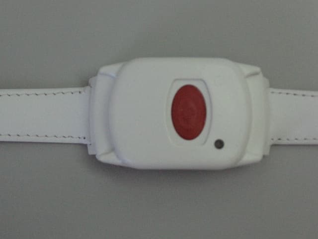
GSAWPK250
Jun 03, 2007PANIC WATCH
Equipment Class
DSC - Part 15 Security/Remote Control Transmitter
GSA5-RLE00125B
May 28, 2007LF Exciter
Equipment Class
DCD - Part 15 Low Power Transmitter Below 1705 kHz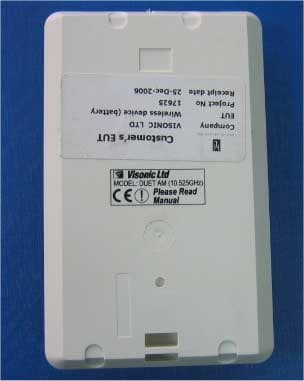
GSADUETAM
May 16, 2007Dual-Technology Microwave/PIR Intrusion Detector
Equipment Class
FDS - Part 15 Field Disturbance Sensor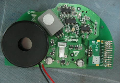
GSAMCT442
May 01, 2007Supervised Indoor Wireless CO Gas Detector
Equipment Class
DSC - Part 15 Security/Remote Control Transmitter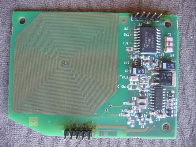
GSAPWRMAXPRO
Jan 17, 2007Security Control Panel
Equipment Class
DSR - Part 15 Remote Control/Security Device Transceiver