GSAMCT442Supervised Indoor Wireless CO Gas Detector
Visonic Inc.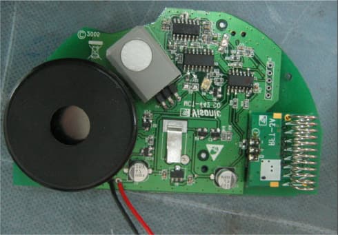
Click to zoom
Application Details
- Equipment Class
- DSC - Part 15 Security/Remote Control Transmitter
- Date of Grant
- May 01, 2007
- Application Purpose
- Original Equipment
- Date of Application
- Apr 30, 2007
- Equipment Note
- Supervised Indoor Wireless CO Gas Detector
- Frequency Range
- 315.00000000 - 315.00000000
- Company
- Visonic Inc.
- Country
- United States
Documents & Files
Document Text
Text extracted from the exhibit documents filed with the FCC. Open a document above to read the original.
Users Manual
D-300273 1 MCT MCTMCT MCT- -- -442 442442 442 Supervised Indoor Wireless CO Gas Detector Installation Instructions 1. INTRODUCTION The carbon monoxide (CO) detector is designed to monitor the CO gas level in residential dwellings and give early warning before potentially dangerous levels exist. The CO alarm is transmitted to the PowerMax+ (version F and up) or PowerMax Pro and presented on its display. The CO gas is considered to be a highly dangerous poisonous gas because it is colorless, odorless, tasteless and very toxic. Presence of CO gas inhibits the blood's capacity to transport oxygen throughout the body, which can eventually lead to brain damage. CO gas is produced by incomplete combustion of fuels (such as natural gas, propane, heating oil, kerosene, coal, charcoal, gasoline or wood) that can occur in any device that depends on burning for energy and heat (such as furnaces, boilers, room heaters, hot water heaters, stoves, grills and in any gasoline powered vehicle or engine). Before CO harmful level is reached, the detector's internal buzzer beeps sound periodically and the detector's red LED flashes. In this condition, the buzzer sound can be stopped for 6 minutes by pressing the TEST/MUTE switch. It will not correct the CO gas problem, but will temporarily silence the buzzer while you correct the problem. After 6 minutes, the detector restarts alarm if the CO level remains high. The detector provides low battery and detector end-of-life indications. Caution: The detector expiry date is stamped on the detector. After the expiry date, the detector should not be used - do not wait for end-of-life indication!! Battery (green) / Fault (yellow) LED TEST / MUTE BUTTON ALARM (red) LED Figure 1 - General View The detector is continuously self-tested and has a TEST button that enables the user to test the detector anytime. Note: The TEST/MUTE switch functions as TEST switch (in normal operation) or as MUTE switch (in alarm condition). The tamper switch actuator (fig. 3), is pressed against the bracket when the unit is attached to the bracket. Removal of the unit from the bracket causes the switch contacts to open, creating a tamper event, which is reported by the transmitter to the alarm system control panel. 2. SPECIFICATIONS CO DETECTION Detection principle: Electrochemical cell Detector Active Life: 5 years maximum Selectable Sensitivity: DIP switch in EN Mode No warning at 30 ppm for 120 minutes, 50 ppm for 60 minutes, 100 ppm for 10 minutes. Warning at 50 ppm between 60-90 minutes, 100 ppm for 10-40 minutes, 150 ppm within 3 minutes. DIP switch in UL Mode No warning at 30 ppm for 30 days, 70 ppm for 60 minutes, 150 ppm for 10 minutes, 400 ppm for 4 minutes. Warning at 70 ppm between 60-240 minutes, 150 ppm for 10- 50 minutes, 400 ppm between 4-15 minutes. Audible Alarm Volume: >95db at a distance of 3m (10 ft.). TRANSMITTER AND CODING Operating Frequency (MHz): 315, 433.92, 868.95 or other frequency according to local requirements. Transmitter's ID Code: 24-bit digital word, over 16 million combinations, pulse width modulation. PowerCode or Zigbee Protocols. Overall Message Length: 36 bits Supervision: Automatic signaling at 60-minute intervals (315 MHz version), 15-minute interval (433.92, 868.95 MHz versions) or according to the local standards. Transmitted Messages: CO gas alarm, low battery, tamper, sensor end of life (5 years), sensor trouble, supervision. Tamper Alerts: Tamper message is transmitted to the PowerMax+ / PowerMax Pro control panel when the detector is removed from its bracket . ELECTRICAL DATA Power Source: 9 volt Lithium battery (Ultra Life #U9VL, U9VL-J). Current Drain: 11 μA standby, 250 μA in operation Battery Life Expectancy: At least 1 year (for typical use) Battery Supervision: Automatic transmission of battery status data as part of any transmitted message. Visual and Audible Indications: Visual Indication (LEDs) Condition Red YellowGreen Audio Indication Alarm 4 flashes (*) - - 4 beeps (*) End of Life / Fault - 3 flashes every 60 sec. - one beep every 60 sec. Battery OK- - Flashes once every minute - Low battery - 1 flash every 60 sec. - one beep every 60 sec. MUTE button is pressed (to silent the alarm for 6 minutes) 4 flashes (*) - - OFF for 6 minutes (**) TEST button is pressed 1 flash (the 1st LED) 1 flash (the 2nd LED) Flashes (the 3rd LED) If CO circuit test and battery are OK - lights during 2 sec. 1 beep * Every 5 seconds during the first 4 minutes, every 60 sec. after the first 4 minutes. ** After 6 minutes, the detector restarts alarm if the CO level remains high. Note: Long period of low battery condition may cause improper function. In case of End-of-Life/Fault indication, replace the battery and check if the End-of-Life/Fault indication still exists. If it still exists, stop using the detector. PHYSICAL DATA Operating Temperature: -10°C to 40°C (14°F to 104°F). Relative Humidity: 10-93% ± 2% RH Dimensions: 127 mm (5 in.) x 40 mm (1-9/16 in.) Weight (without battery): 180g (6.35 oz) Compliance with Standard: EN 50291, UL 2034, BS 7860, CSA-6.19-01 2 D-300273 3. PREPARATIONS 3.1 Disassembly BRACKET DETECTOR 1 Hold the bracket with one hand 2 Rotate the detector as shown and pull it from the bracket Figure 2. Separating the Detector from Its Bracket 3.2 Communication Format Selection Select the desired communication format, EN or UL, by switch 1 (see figure 3). Note: Switch 2 is not used. 3.3 Enrolling the Detector ID Insert battery (see figure 3). Battery cover Function selector: Sw. 1 ON = UL Sw. 1 OFF = EN 9 volts Open battery cover and connect the battery to its terminals (without insulator). Verify proper polarity. Tamper switch actuator Tab (1 of 4) Red button Figure 3. Detector Rear Side The ID of the detector's transmitter must be enrolled in the alarm control panel memory. Refer to the alarm control panel’s installation instructions and follow the procedure given there for enrolling detector's transmitter ID in the control panel's m…
Text truncated - open the document above for the full version.
Block Diagram
No 8, Lane 492, Ba-Der St., Shulin, Taipei Hsien, Taiwan 238 Tel: (886) 2 2668-9668 Fax: (886) 2 2668-9666 www.everday.com Making the World a Safer Place ™ ISO 9001:2000 Certified Company Visonic MCT-442 CO Circuit Frequency a block diagram CPU 250KHZ Change to 500KHZ SENSOR No frequency LED indicator No frequency SOUND3.2KHZ POWER No frequency RF module Selectiveness 315MHZ,433MHZ 868MHZ,869MHZ
Cover Letter(s)
March 7, 2007 American TCB 6731 Whittier Ave Suite C110 McLean, VA 22101 USA Subject: Request for confidentiality for the wireless CO gas detector, model MCT-442, FCC ID:GSAMCT442 Dear Gentlemen, In regards the exhibits submitted in support of the application for FCC ID:GSAMCT442, please classify the following as confidential under the provision of 47 CFR 0.459: 1) Schematic diagram, file “Schematics_17420” (1 page of this Application). The above material contains trade secrets or technical data which Visonic Inc. deems to be proprietary. Therefore this information would customarily be guarded from competitors and cannot be accessible to the general public. Many thanks in advance. Arick Elshtein, International Standards Department Manager
Cover Letter(s)
American Telecommunications Certification Body Inc. 6731 Whittier Ave, McLean, VA 22101 March 18, 2007 RE: Visonic Inc. FCC ID: GSAMCT442 After a review of the submitted information, I have a few comments on the above referenced Application. 1) Please explain the information being presented in Plot 7.1.1 and 7.1.2. One plot appears to transmit in excess of the 5 second requirement and does not appear to be an alarm condition that is life threatening (i.e. not a pending emergency for tamper condition). Tamper appears to take 19 seconds which exceeds the 5 second requirement. 2) From the operational description, for each of the following conditions please explain how the device will transmit: CO gas alarm, low battery, tamper, sensor end of life (5 years), sensor trouble, supervision. Note that for alarm condition of CO, this can transmit continuously since it is a danger to human life. Others are considered a single event and should only transmit a single time < 5 seconds when triggered. Information regarding the low battery, sensor end of life or trouble may be re-transmitted as part of the hourly supervisory transmission, but the original transmissions are considered a single event and limited to the one 5 second transmission. Please explain. 3) If the device is transmitting continuously due to measurement of CO. If CO is not longer detected, please explain if the alarm condition stops/resets. 4) Plot 7.1.4 also appears to exceed the transmit time of 5 seconds. The explanation does not appear to make sense or show compliance (i.e. turn on appears > 5 Seconds) Please explain in further detail. 5) If turn on is > 5 seconds as shown in plot 7.1.4, this appears to be out of compliance as it is expected that the end user may be expected to change the batteries if necessary and then initiate a turn on procedure. This would no longer be under control of a professional installer at this time. 6) If professional installer is being used for any transmissions above, then please note the following interpretation. Inquiry: Regarding 15.231 (a)(5) which states: provided such transmissions are under the control of a professional installer and do not exceed ten seconds after a manually operated switch is released or a transmitter is activated automatically. Such set-up information may include data. Is there any specific guidance that should be submitted by the applicant to support this? Should the device be designed so that only the professional installer can access the functions related to this? Is is sufficient to state in the manual that certain setup/test functions only be used by the installer? Please provide some guidance on what the applicant should provide in their application. Response: The applicant should confirm the following when justifying Professional installation: Professional installation To qualify for professional installation, you must explain why the hardware cannot simply be purchased and installed by the average (technically inclined) person 1) Marketing * The device cannot be sold retail,to the general public or by mail order. It must be sold to dealers. 2) Requires professional installation; - installation must be controlled. - installed by licensed professionals ( EUT sold to dealer who hire installers) - installation requires special training ( special programming, access to keypad, field strength measurements made) What is unique, sophisticated, complex, or specialized about your equipment which REQUIRES it to be installed by a professional installer? 3) Application -The intended use is generally not for the general public. It is generally for industry/commercial use. z Page 2 March 19, 2007 Timothy R. Johnson Examining Engineer mailto: [email protected] The items indicated above must be submitted before processing can continue on the above referenced application. Failure to provide the requested information may result in application termination. Correspondence should be considered part of the permanent submission and may be viewed from the Internet after a Grant of Equipment Authorization is issued. Please do not respond to this correspondence using the email reply button. In order for your response to be processed expeditiously, you must submit your documents through the AmericanTCB.com website. Also, please note that partial responses increase processing time and should not be submitted. Any questions about the content of this correspondence should be directed to the sender.
Cover Letter(s)
HERM O N LA BO RA TO RIES March 29, 2007 American TCB 6731 Whittier Ave Suite C110 McLean, VA 22101 Attn: Mr. T. Johnson, Examining Engineer RE: your e-mail dated March 18, 2007; Visonic Ltd. FCC ID:GSAMCT442, ATCB004652 Dear Mr. Johnson, Please find below the answers to your questions. 1) The “Tamper mode” shown in Plot 7.1.2 is defined by the applicant as alarm mode. The explanation of all modes of operation, file “Signal_general_information_17420” was uploaded on March 29, 2007 via Operational Description folder. 2) Please refer to “Signal_general_information_17420”. 3) As above. 4), 5) Upon replacing its batteries, which occurs very seldom (every two or three years), the product generates 3 transmissions. Each of the 3 transmissions is of 0.2 seconds length with 9 seconds intervals there-between. The three transmissions are used for testing the new battery and for supervision purposes. The regular supervision transmissions are also of 0.2 seconds each and one hour there-between. In the worst case the total transmissions time within two hours window is not more than 0.8 seconds after the replacement of the battery and 0.2 seconds thereafter. Visonic see no objection to transmitting these three transmissions either automatically or manually (depends how you classify battery replacement), nor is the accumulated duration of these transmissions longer than the allowed limits. 6) Not to be used. Marina Cherniavsky, certification engineer Hermon Laboratories
Cover Letter(s)
HERM O N LA BO RA TO RIES April 25, 2007 American TCB 6731 Whittier Ave Suite C110 McLean, VA 22101 Attn: Mr. T. Johnson, Examining Engineer RE: your e-mail dated April 15, 2007; Visonic Ltd. FCC ID:GSAMCT442, ATCB004652 Dear Mr. Johnson, Please find below the answers to your questions. 1) FCC requires ACCUMULATED 2 seconds which can consist of many smaller transmissions, and if you look in our reply to ATCB dated March 29, 2007 (responses 4, 5) the battery replacing plus the supervsion does not exceed 2 seconds. For the “Tamper mode” shown in Plot 7.1.2 Visonic’s answer is always the same, they are sending several messages (in the picture you see 3 messages which is consistent with our reply dated March 29, 2007), the total sum of each of these message is less than 2 seconds !!! The corrected test report VISRAD_FCC.17420_rev1 was uploaded on April 25, 2007. Marina Cherniavsky, certification engineer Hermon Laboratories
External Photos
Visonic Ltd. FCC ID:GSAMCT442 IC:1467C- MCT442 Page 1 of 3 EXTERNAL PHOTOGRAPHS This document contains 2 photographs Visonic Ltd. FCC ID:GSAMCT442 IC:1467C- MCT442 Page 2 of 3 Photograph No.1 Wireless CO gas detector general view Visonic Ltd. FCC ID:GSAMCT442 IC:1467C- MCT442 Page 3 of 3 Photograph No.2 Wireless CO gas detector rear view with a battery removed
ID Label/Location Info
Visonic Ltd. FCC ID:GSAMCT442 IC:1467C- MCT442 Page 1 of 3 Label location Label with FCC ID:GSAMCT442 and IC:1467C-MCT442 will be located at the rear side panel Product Name: LABEL MCT-442 CO DIPSWITCH FCC VISONIC LTD. Apx 2-1-3 Create:Approved: Document No: 4005464 Doc.Rev.: 00 Sheet No./of: 1/1 Name Date Signature Scale: 100% Title: Stamp and Sticker Drawing Upd ECM 12345 0 CONFIDENTIALThis document contains information which is proprietary to Visonic Ltd., Israel. The use, copy or dissemination of this material for any purpose other than that for which it is intended is prohibited without the prior written consent of Visonic Ltd. Date Released: To Whom: Micky L. Yana K. 05.03.07 10 Catalog No.: S-300858 Update: WARNING Carbon monoxide can not be seen or smelled but it can kill you.If alarm signal sounds: 1. Operate reset/silence button. 2. Call your emergency services (fire department or 911). 3. Immediately move to fresh air ñ outdoors or by an open door/window. CAUTION: Read installation instructions. REMINDER · Press the detector's test button once every week. Press the test button until the built-in buzzer sounds and the LEDs flashes sequentially. · Once a month, use a vacuum cleaner to clean the air vents to keep them free of dust. · Replace battery once a year or when a yellow LED flashes & buzzer beeps once in 60 second. · For information contact: Visonic INC. (USA) 10 Northwood drive, Bloomfield CT. 06002-1376. Phone: (860) 243-0833, (800) 223-0020 Visonic LTD. (UK) Fraser Road, Priory business park, Bedford MK44 3WH. Phone: (0870) 7300800 Model Number: Supervised Indoor Wireless CO Gas Detector MCT- 442 (315) Dip SW function: Sw. 1: ON ñ UL Standard. Sw. 1: OFF ñ EN Standard. Sw. 2: NOT USED. 96mm 22mm 45mm 22mm 17mm 14mm 10mm 15mm 30mm FCC ID: GSAMCT442 IC:1467C-MCT442 This device complies with part 15 of the FCC rules.Operation is subject to the following two conditions: (1) this device may not cause harmful interference, and (2) this device must accept any interference received, including interference that may cause undesired operation. S-300858 REV.00 05.03.07 54 mm 23 mm S-300338 REV.0 Operating Voltage -9V DC battery. Battery type: Lithium battery (Ultralife #U9VL, U9VLJ). Product Name: LABLE MCT-442 C0 BATTERYT VISONIC LTD. Apx 2-1-3 Create: Approved: Document No: 4004246 Doc.Rev.: 0 Sheet No./of: 1/1 Name Date Signature Scale: 100% Title: Stamp and Sticker Drawing Upd ECM 12345 0 CONFIDENTIALThis document contains information which is proprietary to Visonic Ltd., Israel. The use, copy or dissemination of this material for any purpose other than that for which it is intended is prohibited without the prior written consent of Visonic Ltd. Date Released: To Whom: Micky L. Yana K. 17.05.06 10343 Catalog No.: S-300338 WARNING Use only batteries specified in marking. Use of a different battery may have detrimental effect on alarm operation. WARNING Constant exposures to high or low temperature or high-humidity may reduce battery life. 17.05.06
Internal Photos
Visonic Ltd. FCC ID:GSA MCT442 IC:1467C- MCT442 Page 1 of 7 INTERNAL PHOTOGRAPHS This document contains 6 photographs Visonic Ltd. FCC ID:GSA MCT442 IC:1467C- MCT442 Page 2 of 7 Photograph No.1 Wireless CO gas detector internal view Visonic Ltd. FCC ID:GSA MCT442 IC:1467C- MCT442 Page 3 of 7 Photograph No.2 Wireless CO gas detector internal view with RF module removed Visonic Ltd. FCC ID:GSA MCT442 IC:1467C- MCT442 Page 4 of 7 Photograph No.3 Detector main PCB front view Visonic Ltd. FCC ID:GSA MCT442 IC:1467C- MCT442 Page 5 of 7 Photograph No.4 Detector main PCB rear side view Visonic Ltd. FCC ID:GSA MCT442 IC:1467C- MCT442 Page 6 of 7 Photograph No.5 RF module front view Visonic Ltd. FCC ID:GSA MCT442 IC:1467C- MCT442 Page 7 of 7 Photograph No.6 RF module rear side view
Operational Description
Visonic Ltd. FCC ID:GSAMCT442 MCT442 operational description The MCT442 is a carbon monoxide (CO) detector designed to monitor the CO gas level in residential dwellings and give early warning before potentially dangerous levels exist. The CO alarm is transmitted to the PowerMax+ (version F and up) or PowerMax Pro and presented on its display. The CO gas is considered to be a highly dangerous poisonous gas because it is colorless, odorless, tasteless and very toxic. Presence of CO gas inhibits the blood's capacity to transport oxygen throughout the body, which can eventually lead to brain damage. CO gas is produced by incomplete combustion of fuels (such as natural gas, propane, heating oil, kerosene, coal, charcoal, gasoline or wood) that can occur in any device that depends on burning for energy and heat (such as furnaces, boilers, room heaters, hot water heaters, stoves, grills and in any gasoline powered vehicle or engine). The transmitter operates at 315 MHz and utilizes a helical integral antenna, the device is powered by 9 V Lithium battery. Transmitted Messages: CO gas alarm, low battery, tamper, sensor end of life (5 years), sensor trouble, supervision. Tamper Alerts: Tamper message is transmitted to the PowerMax+ / PowerMax Pro control panel when the detector is removed from its bracket.
Operational Description
Visonic Ltd. FCC ID:GSAMCT442 - 1 - General information about the MCT442 transmitted signals The MCT 442 transmission signals are very similar to the MCT 425 smoke detector which was tested by Hermon Labs and certified by FCC in 2003 (FCC ID:GSAMCT425). General information about transmitted signals and their duration: 1.1 RF transmitting The detector will send the following messages to Visonic control panel: · CO gas alarm · Low battery · Tamper · Sensor E.O.L (end of life) · Sensor trouble · Supervision The format will be according to Visonic proprietary Power-Code protocol (used in all MCT transmitters approved by FCC, such as MCT 302, MCT 234 and MCT 211) with minor changes. 1.1.1 Alarm message All transmitters will initiate a message transmission when an ALARM condition is detected (CO Alarm, Tamper, Trouble or EOL). Alarm message will be transmitted in 3 message blocks separated randomly by a time that is generated using the ID Code as a seed. Time between blocks = 300 ms+ (value of ID bits 0 to 2) * 60ms. When an alarm is detected, the software should transmit the message without a delay. When a CO ALARM condition is detected, the detector will send message repeatedly up to 30 minutes, when CO concentration becomes lower than the threshold , the alarm stops. 1.1.2 Supervision and Low battery message When a low battery is detected, a flag will rise. Flag will not reset until battery is replaced or program reset (Tamper switch). The battery status will be sent with supervision message (or alarm message). A supervision message is sent every 60 minutes from the last transmission (any transmission). A message will be transmitted in 1 message block. 1.1.3 Coding method The coding uses a return to zero pulse width Manchester code. The transmitters are using key ON-OFF modulation. The message starts with a start pulse after a pause of at least 2T ( 2.4 ms). The start pulse is of the duration of 1/3T (0.4 ms), followed by the message bits (see figure). The end of the start pulse is used as time reference for the next bit, and the end of each bit is the reference for the next one. Bit “0” is starting at 1/3T from the end of the previous bit. Bit “1” will start transmission at 2/3T from the end of the previous bit. The transmission stops always at the end of the bit period. When a CO Alarm, Tamper, Trouble or EOL condition is detected, messages will be transmitted in 3 message blocks. When a SUPERVISION condition is detected, messages will be transmitted in 1 message block. Visonic Ltd. FCC ID:GSAMCT442 - 2 - Each message block is composed of a burst of 6 identical messages, separated by 4 ms from each other - see figure below, the block time is 285 ms. Arick Elshtein, International Standards Department Manager Visonic Ltd.
Test Report
Hermon Laboratories Ltd. P.O.Box 23, Binyamina 30550, Israel Tel. +972-4-6288001 Fax. +972-4-6288277 E-mail: [email protected] Page 1 of 42 Report ID: VISRAD_FCC.17420_rev1.doc Date of Issue: 12/26/2006 Electrical TEST REPORT ACCORDING TO: FCC CFR 47 PART 15 Subpart C, section 15.231 FOR: Visonic Ltd. Wireless CO gas detector Model: MCT-442 This report is in conformity with ISO/ IEC 17025. The A2LA logo endorsement applies only to the test methods and the standards that are listed in the scope of Hermon Laboratories accreditation. The test results relate only to the items tested. This test report shall not be reproduced in any form except in full with the written approval of Hermon Laboratories Ltd. Report ID: VISRAD_FCC.17420_rev1.doc Date of Issue: 12/26/2006 Page 2 of 42 Table of contents 1 Applicant information..................................................................................................................................................... 3 2 Equipment under test attributes .................................................................................................................................... 3 3 Manufacturer information .............................................................................................................................................. 3 4 Test details.................................................................................................................................................................... 3 5 Tests summary.............................................................................................................................................................. 4 6 EUT description............................................................................................................................................................. 5 6.1 General information....................................................................................................................................................... 5 6.2 Operating frequencies ................................................................................................................................................... 5 6.3 Changes made in the EUT ............................................................................................................................................ 5 6.4 Transmitter characteristics ............................................................................................................................................ 6 7 Transmitter tests according to 47CFR part 15 subpart C requirements ........................................................................ 7 7.1 Periodic operation requirements ................................................................................................................................... 7 7.2 Field strength of emissions.......................................................................................................................................... 14 7.3 Occupied bandwidth test ............................................................................................................................................. 25 7.4 Antenna requirements ................................................................................................................................................. 27 7.5 Radiated emission measurements .............................................................................................................................. 28 8 APPENDIX A Test equipment and ancillaries used for tests....................................................................................... 32 9 APPENDIX B Measurement uncertainties................................................................................................................... 33 10 APPENDIX C Test facility description ......................................................................................................................... 34 11 APPENDIX D Specification references ....................................................................................................................... 34 12 APPENDIX E Abbreviations and acronyms................................................................................................................. 35 13 APPENDIX F Test equipment correction factors ......................................................................................................... 36 Report ID: VISRAD_FCC.17420_rev1.doc Date of Issue: 12/26/2006 Page 3 of 42 1 Applicant information Client name: Visonic Ltd. Address: 24 Habarzel st., Tel Aviv 61920, Israel Telephone: 03-6456714 Fax: 03-6456788 E-mail: [email protected] Contact name: Mr. Elshtein Arik 2 Equipment under test attributes Product name: Wireless CO gas detector Product type: Transmitter Model(s): MCT-442 Receipt date 9/28/2006 3 Manufacturer information Manufacturer name: Visonic Ltd. Address: 24 Habarzel st., Tel Aviv 61920, Israel Telephone: 03-6456714 Fax: 03-6456788 E-Mail: [email protected] Contact name: Mr. Elshtein Arik 4 Test details Project ID: 17420 Location: Hermon Laboratories Ltd. P.O.Box 23, Binyamina 30550, Israel Test started: 9/28/2006 Test completed: 11/16/2006 Test specification(s): FCC Part 15, subpart C, ß15.231; subpart B Report ID: VISRAD_FCC.17420_rev1.doc Date of Issue: 12/26/2006 Page 4 of 42 5 Tests summary Test Status Transmitter characteristics Section 15.231(a), Periodic operation requirements Pass Section 15.231(b), Field strength of emissions Pass Section 15.231(c), Occupied bandwidth Pass Section 15.207(a), Conducted emission Not required Section 15.203, Antenna requirement Pass Unintentional emissions Section 15.107, Conducted emission at AC power port Not required Section 15.109, Radiated emission Pass Section 15.111, Conducted emission at receiver antenna port Not required Testing was completed against the relevant requirements of the test standard. T…
Text truncated - open the document above for the full version.
Test Setup Photos
Visonic Ltd. FCC ID:GSA MCT442 IC:1467C- MCT442 Page 1 of 6 SETUP PHOTOGRAPHS This document contains 5 photographs Visonic Ltd. FCC ID:GSA MCT442 IC:1467C- MCT442 Page 2 of 6 Photograph No.1 Setup for periodic transmission and occupied bandwidth measurements Visonic Ltd. FCC ID:GSA MCT442 IC:1467C- MCT442 Page 3 of 6 Photograph No.2 Setup for fundamental and spurious emission field strength measurements in anechoic chamber below 30 MHz Visonic Ltd. FCC ID:GSA MCT442 IC:1467C- MCT442 Page 4 of 6 Photograph No.3 Setup for fundamental and spurious emission field strength measurements in anechoic chamber in 30 MHz – 1000 MHz range Visonic Ltd. FCC ID:GSA MCT442 IC:1467C- MCT442 Page 5 of 6 Photograph No.4 Setup for radiated emission measurements in anechoic chamber, close view Visonic Ltd. FCC ID:GSA MCT442 IC:1467C- MCT442 Page 6 of 6 Photograph No.5 Setup for fundamental and spurious emission field strength measurements in anechoic chamber above 1000 MHz
Contact Information
Applicant
Scott Jensen(Tec Manager)
860-243-0833
Technical Contact
Hermon LaboratoriesAlex Usoskin
[email protected]972-4628-8001
Harakevet Industrial zone · Binyamina · Israel
Non-Technical Contact
Visonic Ltd.Mr. Arick Elshtein
[email protected]972 3645 6714
Test Firm
Hermon Laboratories Ltd.Alexander Usoskin
Technical Specifications
| # | Rule Parts | Frequency Range | Power Output |
|---|---|---|---|
| 1 | 15.231 | 315 MHz - 315 MHz | - |
Other Applications from Visonic Inc.

GSA5-BTC00433
Nov 14, 2007Infant Protection Bracelet
Equipment Class
DSC - Part 15 Security/Remote Control Transmitter
GSAWPK250
Jun 03, 2007PANIC WATCH
Equipment Class
DSC - Part 15 Security/Remote Control Transmitter
GSA5-RLE00125B
May 28, 2007LF Exciter
Equipment Class
DCD - Part 15 Low Power Transmitter Below 1705 kHz
GSADUETAM
May 16, 2007Dual-Technology Microwave/PIR Intrusion Detector
Equipment Class
FDS - Part 15 Field Disturbance Sensor
GSAPWRMAXPRO
Jan 17, 2007Security Control Panel
Equipment Class
DSR - Part 15 Remote Control/Security Device Transceiver