GSADUETAMDual-Technology Microwave/PIR Intrusion Detector
Visonic Inc.
Click to zoom
Application Details
- Equipment Class
- FDS - Part 15 Field Disturbance Sensor
- Date of Grant
- May 16, 2007
- Application Purpose
- Original Equipment
- Date of Application
- Apr 30, 2007
- Equipment Note
- Dual-Technology Microwave/PIR Intrusion Detector
- Frequency Range
- 10525.00000000 - 10525.00000000
- Company
- Visonic Inc.
- Country
- United States
Documents & Files
Document Text
Text extracted from the exhibit documents filed with the FCC. Open a document above to read the original.
Users Manual
D-300431 1 DUET DUETDUET DUET- -- -AM C/O AM C/OAM C/O AM C/O Dual-Technology Microwave/PIR Intrusion Detector Installation Instructions 1. FEATURES 1. FEATURES1. FEATURES 1. FEATURES • Combined Fresnel and cylindrical optics improves detection range and false alarm immunity. • Normally closed and normally open alarm outputs. • Look-down "creep zone" lens. • True Motion Recognition™ (TMR) algorithm (patented) for recognition of true motion of a human body. • DRO-stabilized MW microstrip technology. • MW Motion Simulator simulates the effect of a human body moving in the MW field (patent pending for MW self-test). • Range control for adjusting the MW coverage. • PIR self-test by applying a short heat pulse. • Temperature compensation for the PIR section. • Unique tamper protection mechanism. • Programmable motion event counter (1 or 2 events). • Simple-to-use, three-position vertical adjustment. • TEST input to enable/disable the walk test LED remotely (per new European standard). • Relay output for trouble. • Anti-masking protection. • White light protection. • Optional swivel brackets for wall or ceiling installation. MICROWAVE DETECTOR (HIDDEN) LED (VISIBLE THROUGH LENS WHEN ILLUMINATED) CREEP ZONE LENS PIR SENSOR (BEHIND LENS) SCREW Figure 1. General View 2. SPECIFICATIONS 2. SPECIFICATIONS2. SPECIFICATIONS 2. SPECIFICATIONS Input Voltage: 9 to 16 VDC Current Drain @ 12 VDC: 21 mA standby, 29 mA max. PIR SECTION Sensor: Low noise dual-element pyroelectric type Tripping Indication: LED flashes green for up to 5 seconds Motion Event Verification Counter: Selectable, 1 or 2 events Front Lens Data (see Figure 2) Beams: 32 in two layers (10 curtain beams in bottom layer) Max. Coverage: 20 x 20 m (60 x 60 ft) / 90° field of view Optional Long Range Lens 34D (see figure 2) Beams: 16 Max. Coverage: 25x3m (82x10 ft.) / 6° field of view Vertical Adjustment: FAR, MID and NEAR, by sliding the circuit board along a 3-position scale. MW SECTION Oscillator: Microstrip DRO-stabilized Doppler sensor Frequency: 10.687 GHz (in the UK only) or 10.525 GHz (10.525 GHz for movement detector is prohibited or restricted from use in Austria, Czech Republic, Estonia, Finland, French, Germany, Portugal, Slovak Republic, Turkey, UK, Spain and Sweden). Detection Range Control: Adjustable from 25% to 100% Tripping Indication: LED lights green for up to 5 seconds ALARM, TAMPER & TROUBLE DATA Alarm Indication: LED lights red for 1.5 to 5 seconds if both sensors trip Alarm Output (NC): Solid state, N.C., 0.1 A resistive / 30 VDC; 35 Ω max. internal resistance. Contact opens (1.5 - 5 seconds) in case of alarm event or opens constantly in case of power failure. NO/TRB Output: Solid state, 0.1 A resistive / 30 VDC; 35 Ω max. internal resistance. If DIP switch 3 is in OFF position the contact is normally open type. The contact closes in case of alarm (1.5 - 5 seconds). If DIP switch 3 is in ON position the contact is normally closed type. The contact opens in case of mask detection or in case of internal circuit failure. The contact closes constantly in case of power failure regardless of DIP switch 3 position. Alarm Duration: 1.5 to 5 seconds Tamper Switch: N.C., rated at 50 mA resistive / 30 VDC Masking Detection Delay: About 60 seconds Trouble/ Masking Indication: LED alternately flashes green and red and if DIP switch 3 is in ON position, NO/TRB relay opens until the detector is reset. 20 m151050 2 m TOP VIEW SIDE VIEW (”FAR” POSITION) 90° CURTAINS UPPER LAYER 60 ft453015 Optional long range Lens No. 34D 10 20 30 40 50 60 70 2m (6.5ft) SIDE VIEW TOP VIEW 3 6 9 12 151821 82 ft 25 m Figure 2. Coverage Pattern MOUNTING Form: Surface or corner (no brackets); surface, corner and ceiling with brackets Height: 2 - 2.6 m (6.5 - 8.5 ft) without bracket, 2 - 3.6 m (6.5 - 12 ft) with bracket. Caution: with brackets in use, effective detection ranges may differ from those indicated in Figures 2 and 8. Optional Brackets: BR-1 (surface), BR-2 (corner) and BR-3 (ceiling) ENVIRONMENTAL RFI Protection: >30 V/m up to 1000 MHz. Operating Temperatures: -10°C to 50°C (14°F to 122°F). Storage Temperatures: -20°C to 60°C (-4°F to 140°F). Standards: Complies with Part 15 of the FCC Rules. EN 50131-1 Grade 2 Class II. This device complies with the essential requirements and provisions of Directive 1999/5/EC of the European Parliament and of the Council of 9 March 1999 on radio and telecommunications terminal equipment. See frequency restriction under "Frequency", at the left side. PHYSICAL Dimensions (H X W X D): 123 x 76 x 48 mm (4-13/16 x 3 x 1-7/8 in.) Weight: 145 g (4.5 oz). PATENTS U.S. Patents 5,237,330 and 5,693,943 2 D-300431 3. INSTALLATION 3. INSTALLATION3. INSTALLATION 3. INSTALLATION 3.1 Installation Tips To minimize false alarms: Do not aim at heat sources Mount on solid, stable surfaces Do not expose to air drafts Do not install outdoors Prevent direct sunlight from reaching the detector Keep wiring away from electrical power cables Do not install behind partitions In addition, a few important rules must be observed while selecting a mounting location: A. Microwave radiation passes through glass and non-metallic walls. Be sure to adjust the MW range so that it does not exceed the room limits, or else motion in the next room or moving traffic along the outer side of the wall will cause the MW sensor to trip. B. Large reflecting objects (especially metals) in the coverage area can distort the microwave sensor's coverage pattern. C. If two DUET-AM C/O units are installed in the same room or on opposite sides of a shared wall, they should not face each other and must be mounted at least 2 meters apart. D. Do not install the DUET-AM C/O in places where one of the two sensor circuits alarms constantly or intermittently, due to environmental interference. E. DUET-AM C/O users are advised to mount the unit in locations where inadvertent approach to less than 1 m (3 ft) from the detector is unlikely to occur. 3.2 Mounting A. Remove the f…
Text truncated - open the document above for the full version.
Block Diagram
123450 CONFIDENTIAL This document contains information which is proprietary to Visonic Ltd., Israel. The use, copy or dissemination of this material for any purpose other than that for which it is intended is prohibited with out the prior written consent of Visonic Ltd. Date Released: To Whom: Apx 2-1-3 Designed: Drew: Updated: Approved: Name Date Product Name: Drawing Name: Signature Sheet No./of: Scale: Catalog No.: Drawing No.: File Name: Doc. Rev.: Upd ECOs DUET AM C/O Block Diagram BAABI P. 06.03.07 1/1 E-200380 0 06.03.07 SHVIKI Y. Microcontroller PIC16C711 Tamper Switch PIR Sensor Circuit Microwave Sensor Circuit 10.525 GHZ LED Indicator Green & Red Voltage Regulator DUET AM C/O - Block Diagram Event Counter Alarm Output Output ModeAnti Mask On/OffLED On/Off Test Input Trouble OutputTamper Output DIP Switches Outputs 1 OSC 4MHZ
Cover Letter(s)
March 12, 2007 American TCB 6731 Whittier Ave Suite C110 McLean, VA 22101 USA Subject: Request for confidentiality for the wireless motion detector, model DUET AM, FCC ID:GSADUETAM Dear Gentlemen, In regards the exhibits submitted in support of the application for FCC ID:GSADUETAM, please classify the following as confidential under the provision of 47 CFR 0.459: 1) Schematic diagram, file “Schematics_17625” (1 page of this Application). The above material contains trade secrets or technical data which Visonic Inc. deems to be proprietary. Therefore this information would customarily be guarded from competitors and cannot be accessible to the general public. Many thanks in advance. Arick Elshtein, International Standards Department Manager
Cover Letter(s)
American Telecommunications Certification Body Inc. 6731 Whittier Ave, McLean, VA 22101 April 5, 2007 RE: Visonic Inc. FCC ID: GSADUETAM After a review of the submitted information, I have a few comments on the above referenced Application. 1) Labeling format should be “FCC ID:” note “FCC. ID:” Please correct. Additionally, FYI...IC format is now “IC:” not “CAN:”. 2) The device has a MW adjustment which appears to affect output distance or power. Please ensure that this was set to maximum during testing. 3) Some average plots/measurements appear to use 300 Hz. However average measurements would appear to require > VBW of 33.33 kHz (for 30 uS). Please review. 4) Additionally, it appears that average measurements are not necessary and can simply be adjusted by an averaging factor. However this value does not appear to be used for average results. Please review. 5) It appears incorrect limits were used for 31 GHz. It appears this should be 77.5 dBuV/m. Timothy R. Johnson Examining Engineer mailto: [email protected] The items indicated above must be submitted before processing can continue on the above referenced application. Failure to provide the requested information may result in application termination. Correspondence should be considered part of the permanent submission and may be viewed from the Internet after a Grant of Equipment Authorization is issued. Please do not respond to this correspondence using the email reply button. In order for your response to be processed expeditiously, you must submit your documents through the AmericanTCB.com website. Also, please note that partial responses increase processing time and should not be submitted. Any questions about the content of this correspondence should be directed to the sender.
Cover Letter(s)
American Telecommunications Certification Body Inc. 6731 Whittier Ave, McLean, VA 22101 May 1, 2007 RE: Visonic Inc. FCC ID: GSADUETAM After a review of the submitted information, I have a few comments on the above referenced Application. 1) Your response to previous item 2 appears to refer to the module already being set to maximum. However the users manual clearly explains an MW detection range control of 25% - 100% and also an MW level control on the board. Please explain. Timothy R. Johnson Examining Engineer mailto: [email protected] The items indicated above must be submitted before processing can continue on the above referenced application. Failure to provide the requested information may result in application termination. Correspondence should be considered part of the permanent submission and may be viewed from the Internet after a Grant of Equipment Authorization is issued. Please do not respond to this correspondence using the email reply button. In order for your response to be processed expeditiously, you must submit your documents through the AmericanTCB.com website. Also, please note that partial responses increase processing time and should not be submitted. Any questions about the content of this correspondence should be directed to the sender.
Cover Letter(s)
HERM O N LA BO RA TO RIES April 26, 2007 American TCB 6731 Whittier Ave Suite C110 McLean, VA 22101 Attn: Mr. T. Johnson, Examining Engineer RE: your e-mail dated April 5, 2007; Visonic Ltd. FCC ID:GSADUETAM, ATCB004653 Dear Mr. Johnson, Please find below the answers to your questions. 1) The file “Label_location_17625_rev1” with the revised label was uploaded on April 26, 2007. 2) According to the applicant statement the samples(s) got by Hermon Labs are directly from the production line where Visonic buys the microwave module. The setting of the microwave module can NOT be changed. 3) The measurements were performed in Tx mode, only to show spurious emissions presence in 10.5 to 10.55 GHz range, that’s why VBW was slightly reduced to ensure noise level is under the average limit. Fundamental emission level is not relevant in these particular measurements, it was measured separately with proper setting. 4) The revised test report VISRAD_FCC.17625_rev1 with recalculated Table 7.1.3 was uploaded on April 26, 2007. 5) The revised test report VISRAD_FCC.17625_rev1 with corrected Table 7.1.3 was uploaded on April 26, 2007. Marina Cherniavsky, certification engineer Hermon Laboratories
Cover Letter(s)
HERM O N LA BO RA TO RIES May 10, 2007 American TCB 6731 Whittier Ave Suite C110 McLean, VA 22101 Attn: Mr. T. Johnson, Examining Engineer RE: your e-mail dated May 1, 2007; Visonic Ltd. FCC ID:GSADUETAM, ATCB004653 Dear Mr. Johnson, Please find below the answer of the applicant: Indeed the Microwave module is adjustable, BUT the adjustment is of the RECEIVING sensitivity gain, NOT of the transmit power. Marina Cherniavsky, certification engineer Hermon Laboratories
External Photos
Visonic Ltd. FCC ID:GSADUETAM IC:1467C- DUETAM Page 1 of 3 EXTERNAL PHOTOGRAPHS This document contains 2 photographs Visonic Ltd. FCC ID:GSADUETAM IC:1467C- DUETAM Page 2 of 3 Photograph No.1 Wireless motion detector front view Visonic Ltd. FCC ID:GSADUETAM IC:1467C- DUETAM Page 3 of 3 Photograph No.2 Wireless motion detector rear view
ID Label/Location Info
Visonic Ltd. FCC ID:GSADUETAM IC:1467C- DUETAM Page 1 of 2 Label location Label with FCC ID:GSADUETAM and IC:1467C-DUETAM will be located at the rear side panel Product Name: STAMP DUET AM FCC VISONIC LTD. Apx 2-1-3 Create:Approved: Document No: 4 Doc.Rev.: 00 Sheet No./of: 1/1 Name Date Signature Scale: 100% Title: Stamp and Sticker Drawing Upd ECM 12345 0 CONFIDENTIALThis document contains information which is proprietary to Visonic Ltd., Israel. The use, copy or dissemination of this material for any purpose other than that for which it is intended is prohibited without the prior written consent of Visonic Ltd. Date Released: To Whom: Micky L. Yana K. 07.03.07 10 Catalog No.: S- Update: 05.03.07 VISONIC Model: DUET AM (10.525) FCC ID: GSADUETAM IC: 1467C-DUETAM Made in Israel This device complies with part 15 of the FCC rules. Operation is subject to the following two conditions: (1) this device may not cause harmful interference, and (2) this device must accept any interference received, including interference that may cause undesired operation.
Internal Photos
Visonic Ltd. FCC ID:GSADUETAM IC:1467C- DUETAM Page 1 of 11 INTERNAL PHOTOGRAPHS This document contains 10 photographs Visonic Ltd. FCC ID:GSADUETAM IC:1467C- DUETAM Page 2 of 11 Photograph No.1 Wireless motion detector internal view Visonic Ltd. FCC ID:GSADUETAM IC:1467C- DUETAM Page 3 of 11 Photograph No.2 Wireless motion detector internal view PCB removed Visonic Ltd. FCC ID:GSADUETAM IC:1467C- DUETAM Page 4 of 11 Photograph No.3 Detector main PCB front view Visonic Ltd. FCC ID:GSADUETAM IC:1467C- DUETAM Page 5 of 11 Photograph No.4 Detector main PCB rear side view Visonic Ltd. FCC ID:GSADUETAM IC:1467C- DUETAM Page 6 of 11 Photograph No.5 Detector main PCB without RF module Visonic Ltd. FCC ID:GSADUETAM IC:1467C- DUETAM Page 7 of 11 Photograph No.6 RF module front view Visonic Ltd. FCC ID:GSADUETAM IC:1467C- DUETAM Page 8 of 11 Photograph No.7 RF module rear side view Visonic Ltd. FCC ID:GSADUETAM IC:1467C- DUETAM Page 9 of 11 Photograph No.8 RF module PCB front view Visonic Ltd. FCC ID:GSADUETAM IC:1467C- DUETAM Page 10 of 11 Photograph No.9 RF module internal view Visonic Ltd. FCC ID:GSADUETAM IC:1467C- DUETAM Page 11 of 11 Photograph No.10 Second side of the RF module PCB
Operational Description
The powerful synthesis of PIR and MW technologies with integrated anti-masking detection Visonic’s Duet AM detector with anti-masking combines digital PIR and microwave technologies, to optimize intrusion detection for industrial environments. Advanced infrared and microwave technologies with self test motion simulation ensure total reliability Enhanced anti-masking and tamper-proof mechanism assures immunity to masking and tampering New microstrip DRO stabilized microwave design with unique patented cylindrical lens technology provides superior range, detection and coverage Patented True Motion Recognition (TMR™) enhances detection processing and dramatically reduces false alarms Remote test input and two separate relays ensure easy installation and compliance to latest European EN50131-2 rules Duet AM Dual Technology Detector FEATURES Duet AM Advanced dual-technology detector with integrated anti-masking for industrial environments Visonic reserves the right to change specifications without prior notice. Full warranty statement availble upon request. © VISONIC LTD. 2001 NEXT PIR CE1812S0 (REV 08/01) © VISONIC LTD. 2001 NEXT PIR CE1812S9 (REV 08/01) Web site: http://www.visonic.com Head Office (Israel)Tel (972- 3) 6456789Fax (972-3) 6456788 Visonic Inc. (U.S.A.)Tel (860) 243-0833, (800) 223-0020Fax (860) 242-8094 Visonic Ltd (U.K.)Tel (44-1767) 600857Fax (44-1767) 601098 Visonic Iberica (Spain)Tel (34-91) 413-4575Fax (34-91) 413-4597 Visonic GmbH (Germany)Tel (49-2202) 104930Fax (49-2202) 104959 Visonic Desson (East Asia)Tel (852) 2157-7111Fax (852) 2512 9071 Visonic Rep. (Nordic countries)Tel (47) 6758-0843Fax (47) 6758-0814 Visonic Rep. (Singapor)Tel (66) 223-6768Fax (66) 223-6769 Visonic Rep. (Pacific)Tel (61-2) 9687-1333Fax (61-2) 9687-2333 Duet AM dual-technology detector incorporates Visonic’s digital passive infrared and microwave technologies, guaranteeing long-range coverage, detection accuracy and superior false alarm immunity. The PIR sensor utilizes new advanced Digital Signal Processing (DSP) algorithms, which eliminate the many types of noise and interference that affect the reliability of traditional detectors. Advanced technology embedded in the microwave sensing module increases coverage flexibility and reliability. Unique patented lens design combines Frensel and cylindrical optics for superior detection range. Solid state relays achieve immunity to magnetic field, high reliability and silent operation. Visonic’s patented True Motion Recognition (TMR™) algorithm and advanced circuitry enhance detection of human motion, dramatically reduce false alarms, and guarantee long-term performance. Featuring Visonic’s improved anti-masking technology, the Duet- AM detector utilizes the MW channel to detect and alert upon masking and tampering attempts. To aid the installer, Visonic has added key features for easy installation – separate trouble and alarm dry contact relays, remote test input, easy to use three-position vertical adjustment, and EOL terminal. Software self- tests with true motion simulation of both MW and PIR channels assure greater reliability. Its accurate long-range detection, reliable performance and easy installation make Duet AM the ideal detector for industrial applications. Superior coverage extended to 20 meters Anti-masking for tamper-proof security Remote test input for easy installation and testing Separate solid state relays for ‘trouble/masking’ and ‘alarm’ Combined Fresnel and cylindrical optics (patented) Look-down creep zone lens Easy to use three-position vertical adjustment Compliance with the latest European EN50131-2 security standards SPECIFICATIONS ELECTRICAL Input Voltage: 9 to 16 VDC Current Drain @ 12 VDC: 21 mA standby, 29 mA max. OPTICAL Max. Coverage: 20 x 20 m (60 x 60 ft) / 90 ̊( field of view Vertical Adjustment: FAR, MID and NEAR, by sliding the circuit board along a 3-position scale. MICROWAVE Oscillator: Microstrip DRO-stabilized Doppler sensor Frequency: 10.525 GHz or 10.687 GHz (in the UK only) Detection Range: Adjustable from 25% to 100% (5 m to 20 m) ALARM, TAMPER & TROUBLE DATA Alarm Relay: Solid state, N.C., 0.1 A resistive / 30 VDC; 35Ωmax. internal resistance Alarm Duration: 2 to 3 seconds Tamper Switch: N.C., rated at 50 mA resistive / 30 VDC Trouble Relay: Solid state, N.C., 0.1 A resistive / 30 VDC; 35Ωmax. internal resistance Masking Detection Delay: About 60 seconds MOUNTING Form: Surface or corner (no brackets); surface, corner and ceiling with brackets Height: 2 - 2.6 m (6.5 - 8.5 ft) without bracket, 2 - 3.6 m (6.5 - 12 ft) with bracket. ENVIRONMENTAL RFI Protection: >30 V/m up to 1000 MHz. Operating Temperatures: -10 ̊C to 50 ̊C 14 ̊F to 122 ̊F. Storage Temperatures: -20 ̊C to 60 ̊C -4 ̊F to 140 ̊F. PHYSICAL Size (H X W X D): 123 x 76 x 48 mm (4-13/16 x 3 x 1-7/8 in.) Weight: 145 g (4.5 oz). PATENTS U.S. Patents: 6,211,522 and 5,936,524 (other patents pending) m i c r o w a v e r a n g e 20 m151050 2 m 45301560 ft SIDE VIEW (”FAR” POSITION) CURTAINS UPPER LAYER TOP VIEW 90°
Operational Description
Sheet 1 Rev.04 Mar25, 2005_NJR4178 X-band MIC Doppler Module Frequency: 10.525GHz Applicable Regions: Belgium, Netherlands Model No. NJR4178 Specifications Rev.04 March 25, 2005 Copyright © 2005 New Japan Radio Co., Ltd. Microwave Components Division -Notice of Proprietary Information- This documents and its contents are proprietary to New Japan Radio Co., Ltd. This publication and its contents may not be reproduced or distributed for any other purpose without the written permission of New Japan Radio Co., Ltd. Sheet 2 Rev.04 Mar25, 2005_NJR4178 1. Scope This specification covers the general requirements for X-band microwave doppler module. This module is designed for motion sensing applications. It consists of DRO (Dielectric Resonator Oscillator), balanced Schottky Barrier Diode mixer and Micro- strip Patch Antennas. 2. Features ● Compact Size ● Low Operating Current : 30 mA ● Detection Target Range : 30 m 3. Specifications # Item Specification Electrical Characteristics (at +25C, +5VDC) 1. Operating Voltage 5.0 +/- 0.2 Vdc 2. Operating Current 30 mA typ. 3. Center Frequency 10.525 GHz 4. Frequency Stability +/- 5 MHz max. (-30 to +55 C) 5. Output Power +13 dBm E.I.R.P.typ. 6. Return Loss Sensitivity -90 dBc typ. 7. Second Harmonic Emission 1μW max. 8. Antenna Beamwidth (-3dB) E-Plane H-Plane 36 deg. nom. 72 deg. nom. Pulse Mode Operation 1. Pulse Width 5μsec 2. Duty Cycle 0.01 Absolute Maximum Ratings 1. DC Input Voltage +8 Vdc 2. Operating Temperature Range -30 to +55 C 3. Storage Temperature Rang -40 to +80 C 4. Relative Humidity 95 % at 35 C 5. Vibration G = 10 (f = 30,50 Hz, t = 10min., Direction; X, Y, Z) 6. Shock G = 20 (Half Sine, 10msec., Direction; X, Y, Z) Regulation 1. Regulation for compliance ETS 300 440 Sheet 3 Rev.04 Mar25, 2005_NJR4178 3. Outline Drawing Unit: mm
Test Report
Hermon Laboratories Ltd. P.O.Box 23, Binyamina 30550, Israel Tel. +972-4-6288001 Fax. +972-4-6288277 E-mail: [email protected] Page 1 of 58 Report ID: VISRAD_FCC.17625_rev1.doc Date of Issue: 2/25/2007 Electrical TEST REPORT ACCORDING TO: FCC CFR 47 PART 15 SUBPART C, section 15.245 and subpart B; RSS-210 issue 6 Annex 7 and ICES-003:2004 FOR: Visonic Ltd. Wireless motion detector Model:Duet AM 10.525 GHz This report is in conformity with ISO/ IEC 17025. The A2LA logo endorsement applies only to the test methods and the standards that are listed in the scope of Hermon Laboratories accreditation. The test results relate only to the items tested. This test report shall not be reproduced in any form except in full with the written approval of Hermon Laboratories Ltd. Report ID: VISRAD_FCC.17625_rev1.doc Date of Issue: 2/25/2007 Page 2 of 58 Table of contents 1 Applicant information..................................................................................................................................................... 3 2 Equipment under test attributes .................................................................................................................................... 3 3 Manufacturer information .............................................................................................................................................. 3 4 Test details.................................................................................................................................................................... 3 5 Tests summary.............................................................................................................................................................. 4 6 EUT description............................................................................................................................................................. 5 6.1 General information....................................................................................................................................................... 5 6.2 Ports and lines .............................................................................................................................................................. 5 6.3 Changes made in EUT .................................................................................................................................................. 5 6.4 Test configuration.......................................................................................................................................................... 5 6.5 Transmitter characteristics ............................................................................................................................................ 6 7 Transmitter tests according to 47CFR part 15 subpart C requirements ........................................................................ 7 7.1 Field strength of emissions............................................................................................................................................ 7 7.2 Band edge emission.................................................................................................................................................... 29 7.3 Conducted emissions .................................................................................................................................................. 33 7.4 Antenna requirements ................................................................................................................................................. 36 8 Emission tests according to 47CFR part 15 subpart B and ICES-003 requirements...................................................37 8.1 Conducted emissions .................................................................................................................................................. 37 8.2 Radiated emission measurements .............................................................................................................................. 40 9 APPENDIX A Test equipment and ancillaries used for tests....................................................................................... 46 10 APPENDIX B Test facility description.......................................................................................................................... 48 11 APPENDIX C Specification references ....................................................................................................................... 48 12 APPENDIX D Test equipment correction factors ........................................................................................................ 49 13 APPENDIX E Measurement uncertainties................................................................................................................... 57 14 APPENDIX F Abbreviations and acronyms................................................................................................................. 58 Report ID: VISRAD_FCC.17625_rev1.doc Date of Issue: 2/25/2007 Page 3 of 58 1 Applicant information Client name: Visonic Ltd. Address: 24 Habarzel st., Tel Aviv 61220, Israel Telephone: 03-6456714 Fax: 03-6456788 E-mail: [email protected] Contact name: Mr. Arik Elshtein 2 Equipment under test attributes Product name: Wireless motion detector Product type: Transmitter Model(s): Duet AM 10.525 GHz Serial number: 4178 Receipt date 12/25/2006 3 Manufacturer information Manufacturer name: Visonic Ltd. Address: 24 Habarzel st., Tel Aviv 61220, Israel Telephone: 03-6456714 Fax: 03-6456788 E-Mail: [email protected] Contact name: Mr. Arik Elshtein 4 Test details Project ID: 17625 Location: Hermon Laboratories Ltd. P.O.Box 23, Binyamina 30550, Israel Test started: 12/25/2006 Test completed: 2/02/2007 Test specification(s): FCC Part 15, subpart C, ß15.245 and subpart B; RSS-210, ICES-003:2004 Report ID: VISRAD_FCC.17625_rev1.…
Text truncated - open the document above for the full version.
Test Setup Photos
Visonic Ltd. FCC ID:GSADUETAM IC:1467C- DUETAM Page 1 of 11 SETUP PHOTOGRAPHS This document contains 10 photographs Visonic Ltd. FCC ID:GSADUETAM IC:1467C- DUETAM Page 2 of 11 Photograph No.1 Setup for spurious emission field strength measurements in anechoic chamber below 30 MHz Visonic Ltd. FCC ID:GSADUETAM IC:1467C- DUETAM Page 3 of 11 Photograph No.2 Setup for spurious emission field strength measurements in anechoic chamber in 30 MHz – 1000 MHz range Visonic Ltd. FCC ID:GSADUETAM IC:1467C- DUETAM Page 4 of 11 Photograph No.3 Setup for fundamental and spurious emission field strength measurements in anechoic chamber above 1000 MHz Visonic Ltd. FCC ID:GSADUETAM IC:1467C- DUETAM Page 5 of 11 Photograph No.4 Setup for spurious emission field strength measurements at the OATS from 18 to 26.5 GHz Visonic Ltd. FCC ID:GSADUETAM IC:1467C- DUETAM Page 6 of 11 Photograph No.5 Setup for spurious emission field strength measurements at the OATS from 26.5 to 40 GHz Visonic Ltd. FCC ID:GSADUETAM IC:1467C- DUETAM Page 7 of 11 Photograph No.6 Setup for spurious emission field strength measurements at the OATS above 40 GHz Visonic Ltd. FCC ID:GSADUETAM IC:1467C- DUETAM Page 8 of 11 Photograph No.7 Band edge emission measurement setup at the OATS Visonic Ltd. FCC ID:GSADUETAM IC:1467C- DUETAM Page 9 of 11 Photograph No.8 Radiated emission measurement setup at the OATS, EUT close view Visonic Ltd. FCC ID:GSADUETAM IC:1467C- DUETAM Page 10 of 11 Photograph No.9 Conducted emission measurement setup Visonic Ltd. FCC ID:GSADUETAM IC:1467C- DUETAM Page 11 of 11 Photograph No.10 Conducted emission measurement setup
Contact Information
Applicant
Scott Jensen(Tec Manager)
860-243-0833
Technical Contact
Hermon LaboratoriesAlex Usoskin
[email protected]972-4628-8001
Harakevet Industrial zone · Binyamina · Israel
Non-Technical Contact
Visonic Ltd.Arick Elshtein
[email protected]972 3645 6714
Test Firm
Hermon Laboratories Ltd.Alexander Usoskin
Technical Specifications
| # | Rule Parts | Frequency Range | Power Output |
|---|---|---|---|
| 1 | 15.245 | 10.53 GHz - 10.53 GHz | - |
Other Applications from Visonic Inc.

GSA5-BTC00433
Nov 14, 2007Infant Protection Bracelet
Equipment Class
DSC - Part 15 Security/Remote Control Transmitter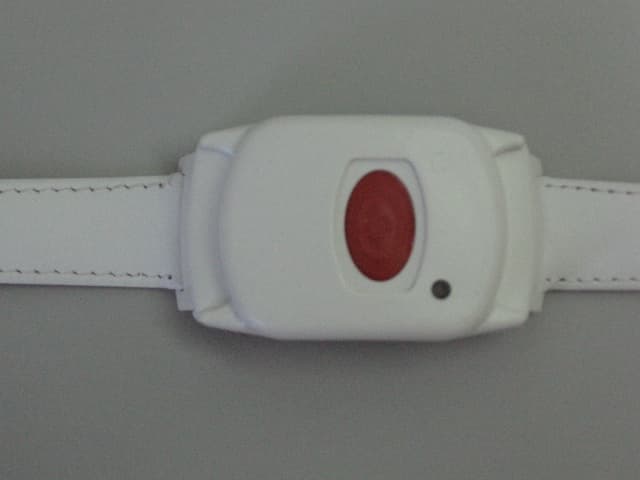
GSAWPK250
Jun 03, 2007PANIC WATCH
Equipment Class
DSC - Part 15 Security/Remote Control Transmitter
GSA5-RLE00125B
May 28, 2007LF Exciter
Equipment Class
DCD - Part 15 Low Power Transmitter Below 1705 kHz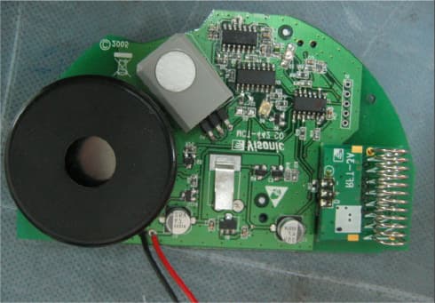
GSAMCT442
May 01, 2007Supervised Indoor Wireless CO Gas Detector
Equipment Class
DSC - Part 15 Security/Remote Control Transmitter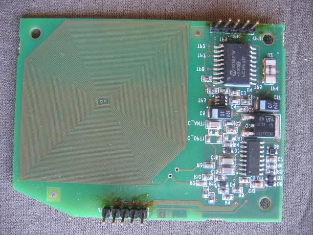
GSAPWRMAXPRO
Jan 17, 2007Security Control Panel
Equipment Class
DSR - Part 15 Remote Control/Security Device Transceiver