GSADISCOVERYQDMCW15.231 Security Remote Control Transmitter
Visonic Inc.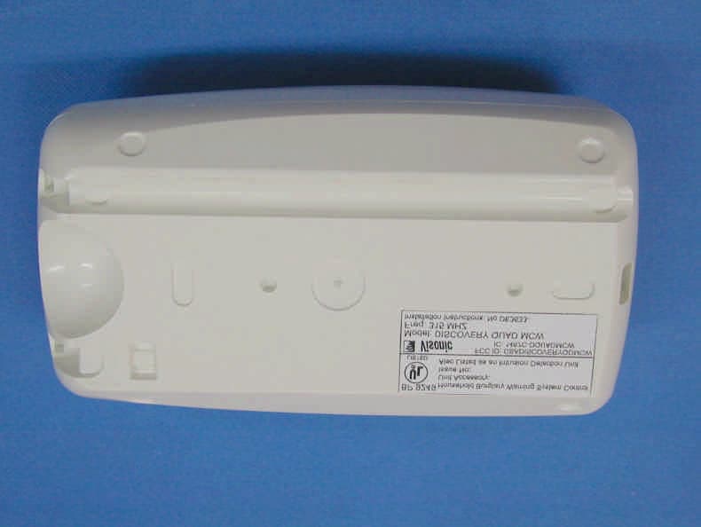
Click to zoom
Application Details
- Equipment Class
- DSC - Part 15 Security/Remote Control Transmitter
- Date of Grant
- Jul 02, 2003
- Application Purpose
- Original Equipment
- Date of Application
- Jul 02, 2003
- Equipment Note
- 15.231 Security Remote Control Transmitter
- Frequency Range
- 315.00000000 - 315.00000000
- Company
- Visonic Inc.
- Country
- United States
Documents & Files
Document Text
Text extracted from the exhibit documents filed with the FCC. Open a document above to read the original.
Users Manual
DE3633 1 DISCOVERY QUAD MCW Wireless PowerCode Quad PIR Detector Installation Instructions 1. FEATURES • Employs a real quad element low-noise pyroelectric sensor • Includes a fully supervised PowerCode transmitter • Patented sophisticated motion analysis algorithm - True Motion Recognition (TMR™) • Two-position vertical adjustment for coverage pattern • Integral swivel bracket for wall or ceiling installation • Programmable motion event counter - ON or OFF (default) • Front and back tamper switches for improved tamper protection • Full stabilization achieved 30 seconds after power up • After detection, the detector disables itself to save battery power. It reverts to the ready state if there is no subsequent detection throughout the following 2-minute period • Automatic termination of walk-test after 15 minutes • Low current consumption • Microprocessor-controlled temperature compensation • Sealed chamber protects the optical system • White light protection • Elegantly styled, sturdy case • Keyhole-shaped slot for easy removal of PCB Figure 1. External View 2. SPECIFICATIONS OPTICAL Detector Type: Quad element low-noise pyroelectric sensor. Detection Pattern: 90° wide angle lens with 19 quad zones in 3 detection layers. Max. coverage is 15 x 15 m (50 x 50 ft). Adjustment: 2-position vertical adjustment scale: FAR and NEAR. Figure 2. Coverage Pattern ELECTRICAL Internal Battery: 3 V Lithium battery, Panasonic CR-2 or equivalent Nominal Battery Capacity: 750 mAh Standby Current Drain: 0.015 mA Transmit Current Drain: 20 mA (including LED) Battery Life Expectancy: 3 years (for typical use) Battery Supervision: Automatic reporting of battery status with each alarm and with periodic supervision message. FUNCTIONAL True Motion Event Verification: 2 position selector - 1 (OFF) or 2 (ON) motion events. Alarm Period: 3 seconds. Visual Indications: LED lights for about 3 seconds upon transmission of alarm & tamper messages and upon each motion detection in the walk test mode. LED flashes during the power-up stabilization period, or after restoring (pressing) the tamper switch. LED does not light upon transmission of supervision messages. Rearm Timer: Rearms the detector 2 minutes after the last alarm. Timer disabled in the walk test mode. WIRELESS Frequency (MHz): 315, 433.92, 868.95, 869.2625 or other frequencies according to local requirements. Transmission Sequence: 3 data bursts at variable intervals within 3 seconds. Encoding: 24-bit ID, over 16 million possible combinations. Total Message Length: 36 bits. Tamper Alert: Reported when a tamper event occurs and in any subsequent message, until the tamper switch is restored. Supervision Message: Once per 15 minutes, 60 minutes or according to local standards. MOUNTING Height: With bracket : Up to 3.6 m (12 ft) Without bracket: 2 - 2.6 m (6.5 - 8.5 ft) Installation Options: With bracket: Surface or ceiling Without bracket: Surface or corner Bracket Adjustment: 20° downward, 20° left and right. ENVIRONMENTAL RFI Protection: >30 V/m up to 1000 MHz. Operating Temperatures: -10°C to 50°C (14°F to 122°F). Storage Temperatures: -20°C to 60°C (-4°F to 140°F). Compliance with Standards: Designed to meet FCC Part 15 and Directive 1999/5/EC of the European Parliament. PHYSICAL Dimensions (H x W x D): 117 x 65 x 47 mm. (4-5/8 x 2-9/16 x 1-7/8 in.). Weight: 92 g (3.25 oz) without bracket, 107 g (3.75 oz) with bracket. Color: White PATENTS: U.S. Patent No. 5,693,943 2 DE3633 3. INSTALLATION 3.1 Installation Hints To minimize false alarms: Do not aim at heat sources Mount on solid, stable surfaces Do not expose to air draughts Do not install outdoors Prevent direct sunlight from reaching the detector Keep wiring away from electrical power cables Do not install behind partitions 3.2 Battery Insertion It is recommended to power up the detector and let the target receiver “learn” the transmitter’s ID before actual installation. This can be done only after battery installation. 1st.Remove the front cover as shown in Figure 3. Figure 3. Cover Removal B. Insert the battery into the battery clip - observe polarity (see Figure 4). 3rd. Press the tamper switch once and release it. This will perform the reset necessary for smooth power up. 4th. Put the cover on and observe the LED. It will flash until the detector stabilizes (within about 30 seconds). 3.3 Enrolling the Transmitter ID Refer to the target receiver’s installation instructions and follow the procedure given there for “teaching” the transmitter's ID. It is much easier to carry out this operation in close proximity to the receiver. 3.4 Mounting without Swivel Bracket 1st.Remove the front cover as shown in Figure 3. 2nd.Loosen the vertical adjustment screw, slide the PCB down and remove it via the “keyhole” (see Figure 4). Figure 4. Inside View 3rd.Punch out the mounting knockouts at the base (for surface mounting) or mounting knockouts at the angled sides of the base (for corner mounting). Attention! The unit has a special tamper switch under the PCB. As long as the PCB is seated firmly within the base, the switch lever will be pressed against a special break-away base segment that is loosely connected to the base (Figure 5). Be sure to fasten the break-away segment to the wall. If the detector unit is forcibly removed from the wall, this segment will break away from the base, causing the tamper switch to open. It is advisable to pierce the anti-tamper knockouts from within the base outward, while pressing the rear surface of the break-away segment against a piece of wood. Figure 5. Anti-Tamper Break-Away Base Segment 4th.Hold the base against the wall at the selected location, mark the drilling points, drill the holes and attach the base to the wall. 5th.Return the PCB to its place: align the ”keyhole” with the head of the vertical adjustment screw, press the PCB against the base, slide the PCB up and temporarily tighten the screw. 3.5 Mounting with Swivel Bracket 1st.Remove the front cover as shown in Figu…
Text truncated - open the document above for the full version.
Block Diagram
MICROCONTROLLER PIC16LC711 QUAD ELEMENT PIR SENSOR TAMPER PULSE COUNTER OFF/ON TRANSMITTER RFT - x BATTERY 3v VOLTAGE DETECTOR (2.7v) LED 4 MHZ BACK TAMPER LED CONTROL OFF/ON NTC DISCOVERY QUAD MCW BLOCK DIAGRAM
Cover Letter(s)
July 2, 2003 American TCB 6731 Whittier Ave Suite C110 McLean, VA 22101 USA Subject: Request for confidentiality for wireless PIR detector, model: Discovery QUAD MCW, FCC ID:GSADISCOVERYQDMCW Dear Gentlemen, We apply to you with request to withhold Visonic Ltd. trade secrets in Application for Certification for wireless PIR detector, FCC ID: GSADISCOVERYQDMCW. These trade secrets can be found in the transmitter schematic diagrams (3 pages of this Application). Many thanks in advance. Yaacov Kotlicki Directing Manager Head Office 30 Habarzel Street Tel Aviv 69710 Israel Postal Address P.O.B. 22020 Tel Aviv 61220 Israel Tel 972 3 6456789 Fax 972 3 6456788
Cover Letter(s)
July 2, 2003 American TCB 6731 Whittier Ave Suite C110 McLean, VA 22101 USA Subject: Application for certification of wireless PIR detector, model: Discovery QUAD MCW, FCC ID:GSADISCOVERYQDMCW Dear Gentlemen, Please find attached our application for certification of wireless PIR detector, FCC ID: GSADISCOVERYQDMCW, prepared in accordance with FCC Rules, parts 15 and 2. The product testing and this application for certification were performed by Hermon Laboratories, which is listed by FCC. Hermon Labs responsible person is Mr. Gonen Usishkin, tel: 011 972 4628 8001, fax:011 972 4628 8277, e-mail: [email protected] . Please send an invoice to Hermon Labs. We hope this application satisfies your requirements. Yaacov Kotlicki Directing Manager Head Office 30 Habarzel Street Tel Aviv 69710 Israel Postal Address P.O.B. 22020 Tel Aviv 61220 Israel Tel 972 3 6456789 Fax 972 3 6456788
External Photos
Front view Rear view
ID Label/Location Info
The identification label (material –polyester) is affixed on the device rear side, as shown in photograph below.
Internal Photos
Internal view PCB first side PCB first side without RF module PCB second side RF module first side RF module second side
Operational Description
DE3633 1 DISCOVERY QUAD MCW Wireless PowerCode Quad PIR Detector Operational description 1. FEATURES • Employs a real quad element low-noise pyroelectric sensor • Includes a fully supervised PowerCode transmitter • Patented sophisticated motion analysis algorithm - True Motion Recognition (TMR™) • Two-position vertical adjustment for coverage pattern • Integral swivel bracket for wall or ceiling installation • Programmable motion event counter - ON or OFF (default) • Front and back tamper switches for improved tamper protection • Full stabilization achieved 30 seconds after power up • After detection, the detector disables itself to save battery power. It reverts to the ready state if there is no subsequent detection throughout the following 2-minute period • Automatic termination of walk-test after 15 minutes • Low current consumption • Microprocessor-controlled temperature compensation • Sealed chamber protects the optical system • White light protection • Elegantly styled, sturdy case • Keyhole-shaped slot for easy removal of PCB Figure 1. External View 2. SPECIFICATIONS OPTICAL Detector Type: Quad element low-noise pyroelectric sensor. Detection Pattern: 90° wide angle lens with 19 quad zones in 3 detection layers. Max. coverage is 15 x 15 m (50 x 50 ft). Adjustment: 2-position vertical adjustment scale: FAR and NEAR. Figure 2. Coverage Pattern ELECTRICAL Internal Battery: 3 V Lithium battery, Panasonic CR-2 or equivalent Nominal Battery Capacity: 750 mAh Standby Current Drain: 0.015 mA Transmit Current Drain: 20 mA (including LED) Battery Life Expectancy: 3 years (for typical use) Battery Supervision: Automatic reporting of battery status with each alarm and with periodic supervision message. FUNCTIONAL True Motion Event Verification: 2 position selector - 1 (OFF) or 2 (ON) motion events. Alarm Period: 3 seconds. 2 DE3633 Visual Indications: LED lights for about 3 seconds upon transmission of alarm & tamper messages and upon each motion detection in the walk test mode. LED flashes during the power-up stabilization period, or after restoring (pressing) the tamper switch. LED does not light upon transmission of supervision messages. Rearm Timer: Rearms the detector 2 minutes after the last alarm. Timer disabled in the walk test mode. WIRELESS Frequency (MHz): 315, 433.92, 868.95, 869.2625 or other frequencies according to local requirements. Transmission Sequence: 3 data bursts at variable intervals within 3 seconds. Encoding: 24-bit ID, over 16 million possible combinations. Total Message Length: 36 bits. Tamper Alert: Reported when a tamper event occurs and in any subsequent message, until the tamper switch is restored. Supervision Message: Once per 15 minutes, 60 minutes or according to local standards. MOUNTING Height: With bracket : Up to 3.6 m (12 ft) Without bracket: 2 - 2.6 m (6.5 - 8.5 ft) Installation Options: With bracket: Surface or ceiling Without bracket: Surface or corner Bracket Adjustment: 20° downward, 20° left and right. ENVIRONMENTAL RFI Protection: >30 V/m up to 1000 MHz. Operating Temperatures: -10°C to 50°C (14°F to 122°F). Storage Temperatures: -20°C to 60°C (-4°F to 140°F). Compliance with Standards: Designed to meet FCC Part 15 and Directive 1999/5/EC of the European Parliament. PHYSICAL Dimensions (H x W x D): 117 x 65 x 47 mm. (4-5/8 x 2-9/16 x 1-7/8 in.). Weight: 92 g (3.25 oz) without bracket, 107 g (3.75 oz) with bracket. Color: White PATENTS: U.S. Patent No. 5,693,943 APPENDIX A. THE VISONIC LTD. POWERCODE SYSTEM A-1. The PowerCode Message Format The PowerCode message transmitted by the DISCOVERY QUAD MCW includes the 24-bit ID and a status report (see Fig. A1). Figure A1. Transmitted Data A message includes the following data: • Detector's ID: Any message transmitted starts with the 24- bit ID assigned to the particular detector unit. • Tamper / Restore: Upon removal of the unit's front cover, a message will be transmitted with a "tamper marker" ON. If the unit's cover is put back, a message will be transmitted with the tamper marker OFF ("Tamper Restore"). • Alarm: Once the detector is in alarm, a message will be transmitted with an "alarm marker" ON. • Low Battery: A special battery condition marker is used to report the battery status in any message. The battery is tested once an hour and if found low, the "low battery marker" is set to ON in all following messages. • Supervision Message: A special "supervision message marker", when set to ON, identifies the periodic supervision messages transmitted automatically at 1 hour or 15 minute intervals. This marker will be OFF in all other messages. • Transmitter Type: A special marker indicates the type of the transmitter: n Supervised or non-supervised n Reports or does not report restorals after alarm The DISCOVERY QUAD MCW does not report restorals after alarms. • Checksum: Checksum bits at the end of the message allow the receiver to determine whether an incoming message is valid (error-free). This feature considerably enhances the reliability of the wireless communication link. A-2. Anti-Collision To overcome message collisions at the receiving end, PowerCode transmitters transmit 3 data bursts at random intervals, with 6 repetitions of the same message in each burst (Fig. A2). This redundancy improves the probability of reception. Note: Periodic supervision messages are an exception to this rule - they consist of a single 6-message burst. Figure A2. Anti-Collision Transmission Sequence WARRANTY Visonic Ltd. and/or its subsidiaries and its affiliates ("the Manufacturer") warrants its products hereinafter referred to as "the Product" or "Products" to be in conformance with its own plans and specifications and to be free of defects in materials and workmanship under normal use and service for a period of twelve months from the date of shipment by the Manufacturer. The Manufacturer's obligations shall be limited within the warranty period, at its option, to repair or replace the product or any part ther…
Text truncated - open the document above for the full version.
Test Setup Photos
Photograph 1 Spurious emission measurement setup in 9 kHz – 30 MHz range, Loop antenna in vertical polarization Photograph 2 Spurious emission measurements in 30 – 2000 MHz range, Biconilog antenna in vertical polarization Photograph 3 Spurious emission measurements in 2000 – 3200 MHz range, Double ridged guide antenna in horizontal polarization Photograph 4 Field strength of fundamental measurements, Log periodic antenna in horizontal polarization Photograph 5 EUT setup view, OATS measurements Photograph 6 EUT setup view, OATS measurements Photograph 7 Harmonics measurements in OATS, Double ridged guide antenna in horizontal polarization
Contact Information
Applicant
Scott Jensen(Tec Manager)
860-243-0833
Technical Contact
Hermon Laboratoriesgonen Usishkin
[email protected]972 4 628 8001
Harakevet Industrial zone · Binyamina · Israel
Test Firm
Hermon Laboratories Ltd.Alexander Usoskin
Technical Specifications
| # | Rule Parts | Frequency Range | Power Output |
|---|---|---|---|
| 1 | 15.231 | 315 MHz - 315 MHz | - |
Other Applications from Visonic Inc.

GSA5-BTC00433
Nov 14, 2007Infant Protection Bracelet
Equipment Class
DSC - Part 15 Security/Remote Control Transmitter
GSAWPK250
Jun 03, 2007PANIC WATCH
Equipment Class
DSC - Part 15 Security/Remote Control Transmitter
GSA5-RLE00125B
May 28, 2007LF Exciter
Equipment Class
DCD - Part 15 Low Power Transmitter Below 1705 kHz
GSADUETAM
May 16, 2007Dual-Technology Microwave/PIR Intrusion Detector
Equipment Class
FDS - Part 15 Field Disturbance Sensor
GSAMCT442
May 01, 2007Supervised Indoor Wireless CO Gas Detector
Equipment Class
DSC - Part 15 Security/Remote Control Transmitter