GSAK980MCWPIR Transmitter
Visonic Inc.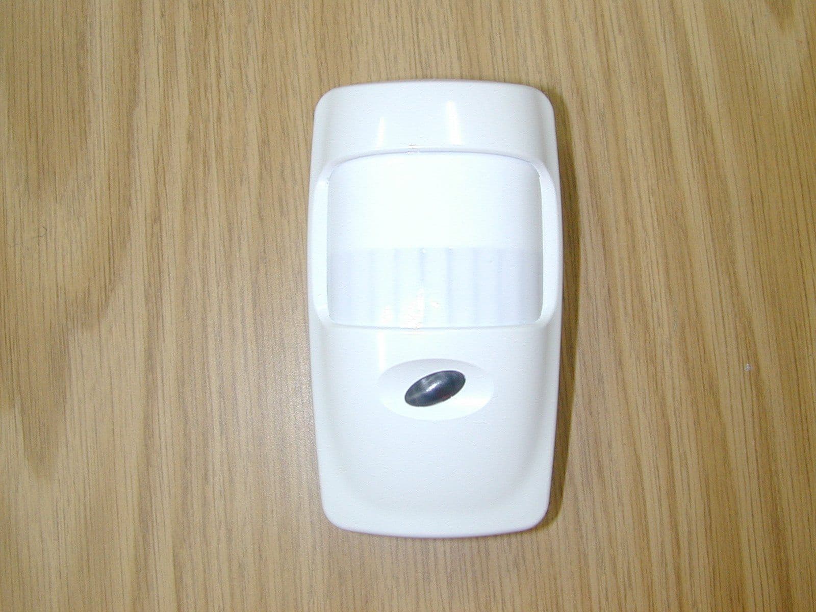
Click to zoom
Application Details
- Equipment Class
- DSC - Part 15 Security/Remote Control Transmitter
- Date of Grant
- Oct 21, 2002
- Application Purpose
- Original Equipment
- Date of Application
- Oct 21, 2002
- Equipment Note
- PIR Transmitter
- Frequency Range
- 315.00000000 - 315.00000000
- Company
- Visonic Inc.
- Country
- United States
Documents & Files
Document Text
Text extracted from the exhibit documents filed with the FCC. Open a document above to read the original.
Users Manual
DE3637 1 KK--980MCW 980MCW Pet-Immune PowerCode Wireless PIR Detector Installation Instructions 1. INTRODUCTION1. INTRODUCTION The K-980MCW is a pet-immune, fully supervised ultra low- current wireless PIR that incorporates a PowerCode transmitter. Both transmitter and detector circuits are powered by an on- board, long life 3.6 V Lithium battery. As a pet immune motion detector, the K-980MCW utilizes TSI™ (Target Specific Imaging) technology that ensures immunity to pets weighing up to 36 kg (80 lb). As a supervised wireless detector, the K-980MCW has a 24-bit ID code, randomly selected in the factory from over 16 million possible combinations. Compatible PowerCode receivers are designed to "learn" specific IDs and respond only to them. Following detection of a human intruder, the K-980MCW triggers the on-board transmitter which transmits its specific PowerCode ID followed by an alarm signal and status designators for tampering and battery condition. Alarm and other data are thus forwarded to the alarm control panel or to a head-end computer, depending on the type of system in which the detector is used. After triggering the transmitter, the K-980MCW inhibits itself to save battery power. The detector reverts to the ready state 2 minutes after the last movement has been detected. An LED/ WALK-TEST jumper is used to override the 2-minute rearm timer during walk testing. Since messages transmitted by the K-980MCW might collide with those transmitted by other Power- Code transmitters, an anti-collision transmission sequence is used. A programmable pulse counter is included in the unit for maximum immunity against false alarms. A periodic test transmission for supervision purposes takes place automatically once an hour. The receiver is thus informed that the Figure 1. General View particular detector is taking an active part in the wireless network. 2. 2. SPECIFICATIONSSPECIFICATIONS OPTICAL Max. Coverage Range: 12 x 12 m (40 x 40 ft) / 90° Pet Immunity: Animals up to 36 kg (80 lb) - not verified by UL. Vertical Adjustment: 3-position adjustment scale: 1.8 m (6 ft), 2.1 m (7 ft) and 2.4 m (8 ft). ELECTRICAL Battery Type: 3.6 Volt lithium thionyl chloride (LiSOCl 2 ) battery, size 1/2AA, Tadiran TL-2150 Nominal Battery Capacity: 1 Ah Standby Current Drain: 0.015 mA Transmit Current Drain: 12 mA (including LED) Figure 2. Coverage Pattern Battery Life Expectancy (not verified by UL): 3 years (for typical use). LED: Lights for 2 seconds upon transmission and upon motion detection in the walk test mode. Detector: Dual-element low-noise pyroelectric sensor. Pulse Counter: Programmable to 1, 3 or 5 pulses. Inhibit Time: 2 minutes after last alarm (none during walk test) WIRELESS Frequency (MHz): 315, 433.92, 868.95, 869.2625 according to local requirements. UL has only investigated at 315 MHz. Transmission Sequence: 3 data bursts at variable intervals within 3 seconds. Encoding: 24-bit ID, over 16 million possible combinations. Total Message Length: 36 bits Battery Supervision: Automatic reporting of low-battery status with each alarm and with periodic autotest. Tamper Alert: Reported at 3-minute intervals ENVIRONMENTAL Operating Temperature: -10° to 49°C (14° to 120°F). Storage Temperature: -20° to 60°C (-4°F to 140°F). RFI Protection: > 30 V/m up to 1000 MHz Compliance with Standards: Meets FCC Part 15, MPT1349 and Directive 1999/5/EC. This device complies with the essential requirements and provisions of Directive 1999/5/EC of the European Parliament and of the Council of 9 March 1999 on radio and telecommunications terminal equipment. PHYSICAL Size (H x W x D): 117 x 65 x 47 mm (4-5/8 x 2-9/16 x 1-7/8 in.). Weight: 97 g (3.4 oz) without bracket. 112 g (4 oz) with bracket. Color: White. 3. 3. INSTALLATIONINSTALLATION 3.1 Installation Tips To minimize false alarms, follow these guidelines: Do not aim at heat sources Mount on solid, stable surfaces 2 DE3637 Do not expose to air drafts Do not install outdoors Prevent direct sunlight from reaching the detector Keep wiring away from electrical power cables Do not install behind partitions The unit must be installed so that the expected motion of a intruder would be perpendicular to the zones of detection. Important! The detector is immune to 36 kg (80 lb) animals moving on the floor or climbing on furniture as long as the activity takes place below 1 m (3 ft). Above the 1 m (3 ft) height limit, the detector is immune to 18 kg (40 lb) pets, but the pet immunity will decrease as the pet gets closer to the detector. It is therefore recommended to select a mounting location that minimizes potential close proximity of animals. These characteristics have not been verified by UL. 3.2 Battery Insertion It is recommended to power up the detector and let the target receiver “learn” the transmitter’s ID before actual installation. 1st.Remove the front cover as shown in Figure 3. Figure 3. Cover Removal B. Insert the battery into the battery clip - observe polarity (see Figure 4). Figure 4. Inside View DE3637 3 3rd. Press the tamper switch once and release it. This will perform the reset necessary for smooth power up. 4th. Put the cover on and watch the LED. It will flash once in 2 seconds for at least 15 seconds until the sensor stabilizes. 3.3 Enrolling the Transmitter ID into the Target Receiver’s Memory Refer to the target receiver’s installation instructions and follow the procedure given there for “teaching” transmitter IDs. It is much easier to carry out this operation in close proximity to the receiver. 3.4 Mounting without Swivel Bracket A. Remove the front cover as shown in Figure 3. B. Loosen the vertical adjustment screw, slide the PCB down and remove it via the “keyhole” (see Figure 4). C. Punch out the mounting knockouts at the rear wall of the base (for surface mounting) or mounting knockouts at the angled sides of the base (for corner mounting). D. Hold the base against the wall at the selected installation location and mark the points for drill…
Text truncated - open the document above for the full version.
Block Diagram
1 2 3 4 5 0 CONFIDENTIAL This document contains information which is proprietary to Visonic Ltd., Israel. The use, copy or dissemination of this material for any purpose other than that for which it is intended is prohibited with out the prior written consent of Visonic Ltd. Date Released: To Whom: Apx 2-1-3 Designed: Drew: Updated: Approved: Name Date Product Name: Drawing Name: Signature Sheet No./of: Scale: Catalog No.: Drawing No.: File Name: Doc. Rev.: UpdECOs K-980 MCW (FCC) Block Diagram BAABI P.22.8.02 1/1 0-3637-1 0F-3637-00 0F363700.VSD 0 MICROCONTROLLER PIR SENSOR TAMPER PULSE COUNTER TRANSMITTER RFT-3A BATTERY LOW BATTERY LED 4 MHZ
Cover Letter(s)
American Telecommunications Certification Body Inc. 6731 Whittier Ave, McLean, VA 22101 October 15, 2002 RE: Visonic Ltd. FCC ID: GSAK980MCW After a review of the submitted information, I have a few comments on the above referenced Application. 1) Please provide external photographs of the back of the unit. 2) Please provide close up internal photographs of the top and bottom of each independent board. 3) The information given in the application states that the unit transmits once per hour to indicate transmitter status for supervisory purposes. As given in 15.231(a)(3) this is only allowed to determine system integrity for applications involving security or safety application ONLY. However, this transmission must be less than 1 second. Please provide information as to how long a single supervisory transmission takes. 4) This application did not include a request for confidentiality. Please confirm that confidentiality is not requested on this application. 5) It appears that the transmitter is contained on a separate board. Please provide the schematic for the TX board. Alternatively, if this board is purchased as an OEM part, please provide a parts list that shows this. 6) Please set the device to transmit normally and provide a plot of 10 seconds showing that once the device is triggered, it automatically stops transmitting in less that 5 seconds. 7) Please note that 1574.98, 2204.8, and 2834.82 MHz fall in restricted bands and are subject to 74 dBuV peak and 54 dBuV Avg limits. Timothy R. Johnson Examining Engineer mailto: [email protected] The items indicated above must be submitted before processing can continue on the above referenced application. Failure to provide the requested information may result in application termination. Correspondence should be considered part of the permanent submission and may be viewed from the Internet after a Grant of Equipment Authorization is issued. Please do not respond to this correspondence using the email reply button. In order for your response to be processed expeditiously, you must submit your documents through the AmericanTCB.com website. Also, please note that partial responses increase processing time and should not be submitted. Any questions about the content of this correspondence should be directed to the sender.
Cover Letter(s)
FCC ID: GSAK980MCW In reply to e-mail dated October 15, 2002 Dear Mr. Johnson, Below are the answers to your questions. 1. Please find an external photograph of the back of the unit (External photo_back.pdf), submitted via "Add to existing application", External photos folder on October 22, 2002. 2. Please find the requested internal photographs (Internal photos_new.pdf), submitted via "Add to existing application", Internal photos folder on October 22, 2002. 3. A supervisory transmission lasts 1/3 s (one burst of 6 messages). This information can be found in Appendix A of the Installation Instructions (A-2. Anti-Collision). 4. Visonic confirms that confidentiality is not requested. 5. Please find schematics of TX board (Tx module_schematics.pdf), submitted via "Add to existing application", Schematics folder on October 22, 2002 6. Please find a 10 s plot in updated Operational description (Oper_descry_updated.pdf), submitted via "Add to existing application", Operational description folder on October 22, 2002. With great respect, Valeria To: "'[email protected]'" <[email protected]> Subject: FCC ID: GSAK980MCW Page 1 of 1In 10/22/2002Printed for "Timothy R. Johnson" <[email protected]>
External Photos
Back of the unit. External view.
ID Label/Location Info
The identification label (material –polyester) is affixed on the device rear side. Label
Internal Photos
Internal view PCB print side
Internal Photos
Internal view PCB, first side PCB, second side Transmitter module, first side Transmitter module, second side
Operational Description
DE3637 1 1. INTRODUCTION1. INTRODUCTION The K-980MCW is a pet-immune, fully supervised ultra low- current wireless PIR that incorporates a PowerCode transmitter. Both transmitter and detector circuits are powered by an on- board, long life 3.6 V Lithium battery. As a pet immune motion detector, the K-980MCW utilizes TSI™ (Target Specific Imaging) technology that ensures immunity to pets weighing up to 36 kg (80 lb). As a supervised wireless detector, the K-980MCW has a 24-bit ID code, randomly selected in the factory from over 16 million possible combinations. Compatible PowerCode receivers are designed to "learn" specific IDs and respond only to them. Following detection of a human intruder, the K-980MCW triggers the on-board transmitter which transmits its specific PowerCode ID followed by an alarm signal and status designators for tampering and battery condition. Alarm and other data are thus forwarded to the alarm control panel or to a head-end computer, depending on the type of system in which the detector is used. After triggering the transmitter, the K-980MCW inhibits itself to save battery power. The detector reverts to the ready state 2 minutes after the last movement has been detected. An LED/ WALK-TEST jumper is used to override the 2-minute rearm timer during walk testing. Since messages transmitted by the K-980MCW might collide with those transmitted by other Power- Code transmitters, an anti-collision transmission sequence is used. A programmable pulse counter is included in the unit for maximum immunity against false alarms. A periodic test transmission for supervision purposes takes place automatically once an hour. The receiver is thus informed that the Figure 1. General View particular detector is taking an active part in the wireless network. 2. SPECIFICA2. SPECIFICATIONSTIONS OPTICAL Max. Coverage Range: 12 x 12 m (40 x 40 ft) / 90° Pet Immunity: Animals up to 36 kg (80 lb) - not verified by UL. Vertical Adjustment: 3-position adjustment scale: 1.8 m (6 ft), 2.1 m (7 ft) and 2.4 m (8 ft). ELECTRICAL Battery Type: 3.6 Volt lithium thionyl chloride (LiSOCl 2 ) battery, size 1/2AA, Tadiran TL-2150 Nominal Battery Capacity: 1 Ah Standby Current Drain: 0.015 mA Transmit Current Drain: 12 mA (including LED) Figure 2. Coverage Pattern Battery Life Expectancy (not verified by UL): 3 years (for typical use). LED: Lights for 2 seconds upon transmission and upon motion detection in the walk test mode. Detector: Dual-element low-noise pyroelectric sensor. Pulse Counter: Programmable to 1, 3 or 5 pulses. Inhibit Time: 2 minutes after last alarm (none during walk test) Antenna: A piece of wire AWG 24, 15 cm long inside the casing is used as an antenna. WIRELESS Frequency (MHz): 315, 433.92, 868.95, 869.2625 according to local requirements. UL has only investigated at 315 MHz. Transmission Sequence: 3 data bursts at variable intervals within 3 seconds. Encoding: 24-bit ID, over 16 million possible combinations. Total Message Length: 36 bits Battery Supervision: Automatic reporting of low-battery status with each alarm and with periodic autotest. Tamper Alert: Reported at 3-minute intervals ENVIRONMENTAL Operating Temperature: -10° to 49°C (14° to 120°F). Storage Temperature: -20° to 60°C (-4°F to 140°F). RFI Protection: > 30 V/m up to 1000 MHz Compliance with Standards: Meets FCC Part 15, MPT1349 and Directive 1999/5/EC. This device complies with the essential requirements and provisions of Directive 1999/5/EC of the European Parliament and of the Council of 9 March 1999 on radio and telecommunications terminal equipment. PHYSICAL Size (H x W x D): 117 x 65 x 47 mm (4-5/8 x 2-9/16 x 1-7/8 in.). Weight: 97 g (3.4 oz) without bracket. 112 g (4 oz) with bracket. Color: White.
Operational Description
DE3637 1 1. INTRODUCTION1. INTRODUCTION The K-980MCW is a pet-immune, fully supervised ultra low- current wireless PIR that incorporates a PowerCode transmitter. Both transmitter and detector circuits are powered by an on- board, long life 3.6 V Lithium battery. As a pet immune motion detector, the K-980MCW utilizes TSI™ (Target Specific Imaging) technology that ensures immunity to pets weighing up to 36 kg (80 lb). As a supervised wireless detector, the K-980MCW has a 24-bit ID code, randomly selected in the factory from over 16 million possible combinations. Compatible PowerCode receivers are designed to "learn" specific IDs and respond only to them. Following detection of a human intruder, the K-980MCW triggers the on-board transmitter which transmits its specific PowerCode ID followed by an alarm signal and status designators for tampering and battery condition. Alarm and other data are thus forwarded to the alarm control panel or to a head-end computer, depending on the type of system in which the detector is used. After triggering the transmitter, the K-980MCW inhibits itself to save battery power. The detector reverts to the ready state 2 minutes after the last movement has been detected. An LED/ WALK-TEST jumper is used to override the 2-minute rearm timer during walk testing. Since messages transmitted by the K-980MCW might collide with those transmitted by other Power- Code transmitters, an anti-collision transmission sequence is used. A programmable pulse counter is included in the unit for maximum immunity against false alarms. A periodic test transmission for supervision purposes takes place automatically once an hour. The receiver is thus informed that the Figure 1. General View particular detector is taking an active part in the wireless network. 2. SPECIFICA2. SPECIFICATIONSTIONS OPTICAL Max. Coverage Range: 12 x 12 m (40 x 40 ft) / 90° Pet Immunity: Animals up to 36 kg (80 lb) - not verified by UL. Vertical Adjustment: 3-position adjustment scale: 1.8 m (6 ft), 2.1 m (7 ft) and 2.4 m (8 ft). ELECTRICAL Battery Type: 3.6 Volt lithium thionyl chloride (LiSOCl 2 ) battery, size 1/2AA, Tadiran TL-2150 Nominal Battery Capacity: 1 Ah Standby Current Drain: 0.015 mA Transmit Current Drain: 12 mA (including LED) Figure 2. Coverage Pattern Battery Life Expectancy (not verified by UL): 3 years (for typical use). LED: Lights for 2 seconds upon transmission and upon motion detection in the walk test mode. Detector: Dual-element low-noise pyroelectric sensor. Pulse Counter: Programmable to 1, 3 or 5 pulses. Inhibit Time: 2 minutes after last alarm (none during walk test) Antenna: A piece of wire AWG 24, 15 cm long inside the casing is used as an antenna. WIRELESS Frequency (MHz): 315, 433.92, 868.95, 869.2625 according to local requirements. UL has only investigated at 315 MHz. Transmission Sequence: 3 data bursts at variable intervals within 3 seconds. Encoding: 24-bit ID, over 16 million possible combinations. Total Message Length: 36 bits Battery Supervision: Automatic reporting of low-battery status with each alarm and with periodic autotest. Tamper Alert: Reported at 3-minute intervals ENVIRONMENTAL Operating Temperature: -10° to 49°C (14° to 120°F). Storage Temperature: -20° to 60°C (-4°F to 140°F). RFI Protection: > 30 V/m up to 1000 MHz Compliance with Standards: Meets FCC Part 15, MPT1349 and Directive 1999/5/EC. This device complies with the essential requirements and provisions of Directive 1999/5/EC of the European Parliament and of the Council of 9 March 1999 on radio and telecommunications terminal equipment. PHYSICAL Size (H x W x D): 117 x 65 x 47 mm (4-5/8 x 2-9/16 x 1-7/8 in.). Weight: 97 g (3.4 oz) without bracket. 112 g (4 oz) with bracket. Color: White. A 10 s plot, showing that transmitter stops transmitting in less than 5 s :
Schematics
ee363700_739229.sch-1 - Mon Oct 07 11:12:21 2002
Test Report
This report is in conformity with ISO/IEC 17025. The A2LA logo endorsement applies only to the test methods and the standards that are listed in the scope of Hermon Laboratories accreditation. The test results relate only to the items tested. This test report must not be reproduced in any form except in full with the approval of Hermon Laboratories Ltd. Page 1 of 38 Document ID: visrad_fcc.15174.doc Date of Issue: July 02 HERMON LABORATORIES Electrical Hermon Laboratories Ltd. P.O.Box 23 Binyamina 30550, Israel Tel.+972 66288001 Fax.+972 66288277 e-mail: [email protected] RADIO TEST REPORT ACCORDING TO 47 CFR Part 15 SUBPART C §15.231, §15.205, §15.209 and SUBPART B; RSS-210 Issue 5:2001; ICES-003 Issue 3:1997 for VISONIC Ltd. EQUIPMENT UNDER TEST: Pet immune wireless detector Model: K-980MCW @ 315 MHz Page 2 of 38 Document ID: visrad_fcc.15174.doc Date of Issue: July 02 HERMON LABORATORIES Contents CONTENTS.............................................................................................................................................................................. 2 1 PROJECT INFORMATION............................................................................................................................................... 3 2 SUMMARY OF TESTS AND REQUIREMENTS .............................................................................................................. 4 3 EUT DESCRIPTION ......................................................................................................................................................... 6 3.1 G ENERAL DESCRIPTION ................................................................................................................................................ 6 3.2 EUT TEST CONFIGURATION .......................................................................................................................................... 6 3.3 T RANSMITTER DESCRIPTION .......................................................................................................................................... 7 4 TEST RESULTS ............................................................................................................................................................... 8 4.1 B ANDWIDTH OF EMISSION ACCORDING TO § 15.231 ( C ) AND RSS-210 § 6.1.1( C ) ............................................................ 8 4.2 F IELD STRENGTH OF FUNDAMENTAL , § 15.231 AND RSS-210 § 6.1.1( B )......................................................................... 9 4.3 F IELD STRENGTH OF SPURIOUS RADIATION , § 15.231 AND RSS-210 § 6.1.1( B ) ............................................................. 10 4.4 U NINTENTIONAL RADIATED EMISSIONS TEST ACCORDING TO §15.109 AND ICES-003....................................................... 11 APPENDIX A - PLOTS ........................................................................................................................................................... 12 APPENDIX B – TEST SETUP PHOTOGRAPHS ................................................................................................................... 27 APPENDIX C - TEST EQUIPMENT USED FOR TESTS ....................................................................................................... 30 APPENDIX E TEST EQUIPMENT CORRECTION FACTORS.............................................................................................. 31 APPENDIX E - GENERAL INFORMATION............................................................................................................................ 37 T EST FACILITY DESCRIPTION ................................................................................................................................................... 37 A BBREVIATIONS AND ACRONYMS ............................................................................................................................................. 37 S PECIFICATION REFERENCES .................................................................................................................................................. 37 FCC E QUIPMENT CODES AND DESCRIPTIONS ........................................................................................................................... 38 Page 3 of 38 Document ID: visrad_fcc.15174.doc Date of Issue: July 02 HERMON LABORATORIES 1 Project information Description of equipment under test Test items : Pet immune wireless detector Manufacturer : Visonic Ltd. Brand name : K-980MCW Equipment serial number : Cat No 0-3637-1 Types (Models) : K-980MCW @ 315 MHz Equipment FCC code 1 : DSC Applicant information Applicant’s responsible person : Mr. Arick Elshtein, project manager Company : Visonic Ltd. Address : 27 Habarzel Street Postal code : 69710 City : Tel Aviv Country : Israel Telephone number : +972 3 6456714 Telefax number : +972 3 6456891 Test performance Project Number: : 15174 Location : Hermon Laboratories Receipt date : July 1, 2002 Test performed : July 11, 2002 Purpose of test : Apparatus compliance verification in accordance with emission requirements Test specification(s) : 47CFR Part 15, subpart C, §15.231, §15.205, §15.209, and subpart B §15.109; RSS-210 Issue 5: 2001 and ICES-003 Issue 3: 1997 1 FCC Equipment codes – see Appendix D Page 4 of 38 Document ID: visrad_fcc.15174.doc Date of Issue: July 02 HERMON LABORATORIES Hermon Laboratories Ltd. P.O.Box 23 Binyamina 30550, Israel Tel.+972 66288001 Fax.+972 66288277 e-mail: [email protected] 2 Summary of tests and requirements Parameter Subclause C NC NT NA Tested by Date tested Remarks Transmitter characteristics, §15.231 Periodic operation 15.231(a) X Refer to Installation instructions Bandwidth of emission 15.231(c) X Mrs. E. Pitt, test engineer July 8, 2002 Field strength of fundamental 15.231(b)(2) X Mr. M. Feldman, test engineer July 1, 2002 Field strength of spurious radiation 15.231(b)(3) X Mrs. E. Pitt, test engineer Jul…
Text truncated - open the document above for the full version.
Test Setup Photos
Test setup with loop antenna Test setup with log-periodic antenna EUT test setup
Contact Information
Applicant
Scott Jensen(Tec Manager)
860-243-0833
Technical Contact
Hermon LaboratoriesEdward Usoskin
[email protected]972 4 628 8001
Harakevet Industrail zone · Binyamina · Israel
Non-Technical Contact
Visonic Ltd.Arick Elshtein
[email protected]972 3 6456714
Test Firm
Hermon Laboratories Ltd.Alexander Usoskin
Technical Specifications
| # | Rule Parts | Frequency Range | Power Output |
|---|---|---|---|
| 1 | 15.231 | 315 MHz - 315 MHz | - |
Other Applications from Visonic Inc.

GSA5-BTC00433
Nov 14, 2007Infant Protection Bracelet
Equipment Class
DSC - Part 15 Security/Remote Control Transmitter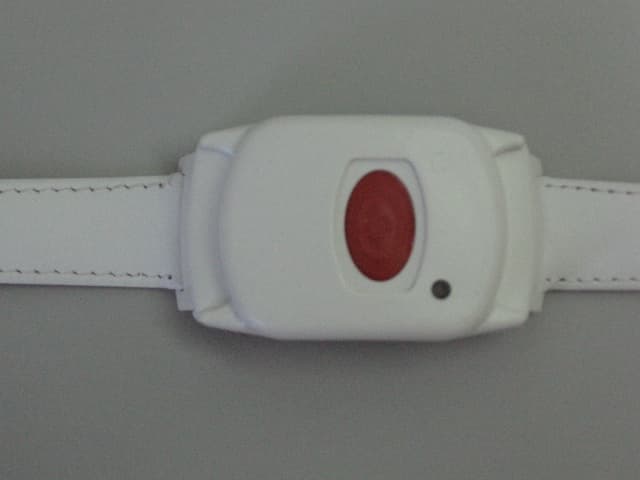
GSAWPK250
Jun 03, 2007PANIC WATCH
Equipment Class
DSC - Part 15 Security/Remote Control Transmitter
GSA5-RLE00125B
May 28, 2007LF Exciter
Equipment Class
DCD - Part 15 Low Power Transmitter Below 1705 kHz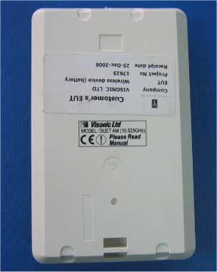
GSADUETAM
May 16, 2007Dual-Technology Microwave/PIR Intrusion Detector
Equipment Class
FDS - Part 15 Field Disturbance Sensor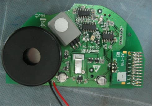
GSAMCT442
May 01, 2007Supervised Indoor Wireless CO Gas Detector
Equipment Class
DSC - Part 15 Security/Remote Control Transmitter