GSAK980WMotion Detector
Visonic Inc.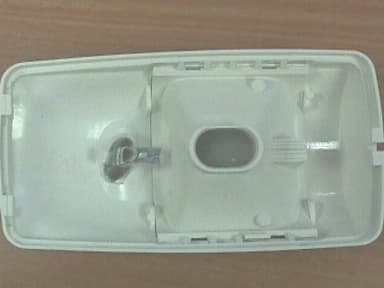
Click to zoom
Application Details
- Equipment Class
- DSC - Part 15 Security/Remote Control Transmitter
- Date of Grant
- Feb 13, 2000
- Application Purpose
- Original Equipment
- Date of Application
- Nov 13, 1999
- Equipment Note
- Motion Detector
- Frequency Range
- 315.00000000 - 315.00000000
- Company
- Visonic Inc.
- Country
- United States
Documents & Files
Document Text
Text extracted from the exhibit documents filed with the FCC. Open a document above to read the original.
Users Manual
DE35821 K-980W K-980WK-980W K-980W Pet-immune Wireless PIR Motion Detector Installation Instructions 1. FEATURES 1. FEATURES1. FEATURES 1. FEATURES • Uses TSI™ (Target Specific Imaging) technology for distinction between humans and pets • Immune to pets weighing up to 36 kg (80 lb) • Integral swivel bracket for wall or ceiling installation • Sealed chamber protects the optical system • On-board CE and FCC approved transmitter • Programmable pulse counter (1, 2, 3 or 5 pulses) • 9 Volt battery powered, with unique energy saving circuitry • Extremely-low current consumption – 0.013 mA • Automatically inhibited after detecting motion; reverts to the ready state if no motion is detected for 2 minutes. • A TEST/NORMAL selector eliminates the 2-minute inhibit period and sets the pulse counter to 1-pulse during walk testing. • Automatic transmission of low-battery and tamper alerts • Three-position vertical adjustment • White light protection • Programmable 8-bit system code and 4-bit channel code • Surface and corner mounting • Rejects RF interference up to 1000 MHz • Elegantly styled, sturdy case • Keyhole-shaped slot for easy removal of PCB Figure 1. The K-980W Wireless Detector 2. SPECIFICATIONS 2. SPECIFICATIONS2. SPECIFICATIONS 2. SPECIFICATIONS OPTICAL Max. Coverage Range: 9 x 9 m (30 x 30 ft) / 90 ° Pet Immunity: Immune to pets weighing up to 36 kg (80 lb) under optimal environmental conditions. Vertical Adjustment: 3-position adjustment scale: 1.8 m (6 ft), 2.1 m (7 ft) and 2.4 m (8 ft). ELECTRICAL Voltage: 9 Volt alkaline or lithium battery. Standby Current: 0.013 mA. LED: Walk Test & transmission. Detector: Dual-element low-noise pyroelectric sensor. Pulse Counter: Programmable to 1, 2, 3 or 5 pulses with walk-test override. Inhibit Timer: re-enables the unit about 2 minutes after alarm, if no further motion is detected. WIRELESS Frequency (MHz): 315, 304, 404, 418, 433.92 or other frequencies according to local requirements. Alarm Transmission Duration: 2 seconds. Encoding: 8-bit digital word, 256 combinations, pulse width modulation. Channels: 4 channels, switch selectable. Battery Test: Automatic transmission of "Code 0" at 2-minute intervals if the battery voltage drops below 7 V. Tamper Alert: Transmission of the "Channel 2" code at 2-minute intervals, until the tamper switch is restored. ENVIRONMENTAL Operating Temperature: -10°C to 50°C (14°F to 122°F). Storage Temperature: -20° to 60°C (-4°F to 140°F). RFI Protection: Greater than 30 V/m up to 1000 MHz. Note: The temperature range may be reduced due to battery characteristics. Compliance with Standards: Meets FCC Part 15 requirements; The 433.92 MHz version complies with the European Council Directive EMC 89/336/EEC & 92/31/EEC, and bears the CE mark and certification. MOUNTING Height: 1.8 to 2.4 m (6 to 8 ft) Installation Options: Surface or corner (without bracket); surface or ceiling (with bracket). Bracket Adjustment: 20 ° downward (only in non-pet immune applications), 20 ° left and right. PHYSICAL Dimensions (H x W x D): 117 x 65 x 47 mm. (4-5/8 x 2-9/16 x 1-7/8 in.). Weight: 92 g (3.25 oz) without bracket, 107 g (3.8 oz) with bracket. Color: White 2DE3582 3. INSTALLATION 3. INSTALLATION3. INSTALLATION 3. INSTALLATION 3.1 Installation Hints Important! Under optimal environmental conditions, the detector is immune to animals weighing up to 36 kg (80 lb) that move on the floor or climb on furniture, as long as this activity takes place below 1 m (3 ft). Above 1 m (3 ft), the detector is immunetopets weighing 18 kg (40 lb), but the pet immunity will decrease as the pet gets closer to the detector. It is therefore recommended to select a mounting location that minimizes potential close proximity of animals. When installing keep in mind the advice given in Figure 2 below: Do not aim at heat sources Mount on solid, stable surfaces Do not expose to air draftsDo not install outdoors Prevent direct sunlight from reaching the detector Keep wiring away from electrical power cables Do not install behind partitions Figure 2. Installation Hints 3.2 Mounting without Swivel Bracket 1st. Remove the front cover as shown in Figure 3. Figure 3. Cover Removal 2nd. Loosen the vertical adjustment screw, slide the PCB down and remove it via the “keyhole” (see Figure 4). 3rd. Pull the PCB straight out and put it aside until required again. 4th. Refer to Figure 4 and punch out the mounting knockouts at the rear wall of the base (for surface mounting) or mounting knockouts at the angled sides of the base (for corner mounting). 5th. Hold the base against the wall at the selected installation location and mark the points for drilling. 6th. Drill the holes and insert the plastic anchors supplied (if necessary). 7th. Return the PCB to its place: align the ”keyhole” with the head of the vertical adjustment screw, press the PCB against the base, slide the PCB up and adjust it as explained in Para. 3.8. Figure 4. Inside View 3.3 Mounting with Swivel Bracket 1st. Remove the front cover as shown in Figure 3. 2nd. Remove the PCB and put it temporarily aside. 3rd. Punch out the large knockout in the round bulge at the top part of the base (see Figure 5) Figure 5. Attaching the Bracket 4th. Assemble the bracket as shown in Figure 5. 5th. Rotate the bracket to the desired position (see Figure 6) but do not yet tighten the screw fully. DE35823 Figure 6. Wall and Ceiling Positions of Bracket 6th. Press the bracket against the mounting surface and mark the points for drilling. Drill out the holes and insert plastic anchors. 7th. Attach the bracket to the mounting surface using the two screws supplied. H.Swivel the detector horizontally to face the desired direction, but do not tilt it if this is a pet immune application. However, if pets are not present it is advisable to tilt the detector as much as 20 ° down. Figure 7 shows the tilt/swivel possibilities. Figure 7. Tilt/Swivel Limits I.Once the detector is directed as desired, tighten the bracket assembly screw…
Text truncated - open the document above for the full version.
Users Manual
DE35801 LEGACY LEGACYLEGACY LEGACY Advanced Wireless PIR Motion Detector Installation Instructions 1. FEATURES 1. FEATURES1. FEATURES 1. FEATURES The LEGACY wireless PIR is an advanced microprocessor- controlled, low-current PIR detector incorporating an on-board miniature UHF transmitter. Following detection, the LEGACY activates the on-board UHF transmitter for 2 seconds, then disarms itself to save battery power. The detector rearms itself (reverts to the ready state) automatically 2 minutes after the last movement has been detected. A TEST/NORMAL selector is used to override the 2- minute rearm timer during walk testing. A feature summary of the LEGACY detector is given below. • Integral swivel bracket for wall or ceiling installation • Sealed chamber protects the optical system • On-board CE and FCC approved transmitter module • 9 Volt battery powered, with unique energy saving circuitry • Extremely-low current consumption – 0.013 mA • Sends automatic low-battery and tamper alerts • Programmable pulse counter (1, 2, 3 or 5 pulses) • Two-position vertical adjustment • White light protection • Programmable 8-bit system code and 4-bit channel code • Surface and corner mounting • Rejects RF interference up to 1000 MHz • Elegantly styled, sturdy case • Keyhole-shaped slot for easy removal of PCB Figure 1. The LEGACY Wireless Detector 2. SPECIFICATIONS OPTICAL Detection Pattern: 90 ° wide angle lens with 36 beams in 3 detection layers. Max. coverage is 15 x 15 m (50 x 50 ft). Adjustment: 2-position vertical adjustment: FAR and NEAR. ELECTRICAL Voltage: 9 Volt alkaline or lithium battery. Standby Current: 0.013 mA. LED: Walk Test & transmission. Detector: Dual-element low-noise pyroelectric sensor. Pulse Counter: Programmable to 1, 2, 3 or 5 pulses with walk-test override. Rearm Timer: Rearms the unit about 2 minutes after the last alarm; the timer is disabled in the walk test mode. Figure 2. Coverage Pattern WIRELESS Frequency (MHz): 315, 304, 404, 418, 433.92 or other frequencies according to local requirements. Alarm Transmission Duration: 2 seconds. Encoding: 8-bit digital word, 256 combinations, pulse width modulation. Channels: 4 channels, switch selectable. Battery Test: Automatic transmission of "Code 0" at 2-minute intervals if the battery voltage drops below 7 V. Tamper Alert: Transmission of the "Channel 2" code at 2-minute intervals, until the tamper switch is restored. ENVIRONMENTAL Operating Temperature: -10°C to 50°C (14°F to 122°F). Storage Temperature: -20° to 60°C (-4°F to 140°F). RFI Protection: Greater than 30 V/m up to 1000 MHz. Note: The temperature range may be reduced due to battery characteristics. Compliance with Standards: This device complies with the European Council Directive EMC 89/336/EEC & 92/31/EEC, and bears the CE mark and certification. MOUNTING Height: 2.0 to 2.6 m (6.5 to 8.5 ft) Room Size: Up to 15 m (50 ft) in the “FAR” position 2 - 8 m (6 - 24 ft) in the NEAR position. Installation Options: Surface or corner (without bracket); surface or ceiling (with bracket). Bracket Adjustment: 20 ° downward, 20° left and right. PHYSICAL Dimensions (H x W x D): 117 x 65 x 47 mm (4-5/8 x 2-9/16 x 1-7/8 in.). Weight: 92 g (3.25 oz) without bracket, 107 g (3.8 oz) with bracket. Color: White 2DE3580 3. INSTALLATION 3. INSTALLATION3. INSTALLATION 3. INSTALLATION 3.1 Installation Hints To minimize false alarms: Do not aim at heat sources Mount on solid, stable surfaces Do not expose to air draftsDo not install outdoors Prevent direct sunlight from reaching the detector Keep wiring away from electrical power cables Do not install behind partitions 3.2 Mounting without Swivel Bracket 1st. Remove the front cover as shown in Figure 3. Figure 3. Cover Removal 2nd. Loosen the vertical adjustment screw, slide the PCB down and remove it via the “keyhole” (see Figure 4). 3rd. Pull the PCB straight out and put it aside until required again. 4th. Refer to Figure 4 and punch out the mounting knockouts at the rear wall of the base (for surface mounting) or mounting knockouts at the angled sides of the base (for corner mounting). 5th. Hold the base against the wall at the selected installation location and mark the points for drilling. 6th. Drill the holes and insert the plastic anchors supplied (if necessary). 7th. Return the PCB to its place: align the ”keyhole” with the head of the vertical adjustment screw, press the PCB against the base, slide the PCB up and adjust it as explained in Para. 3.8. Figure 4. Inside View 3.3 Mounting with Swivel Bracket 1st. Remove the front cover as shown in Figure 3. 2nd. Remove the PCB and put it temporarily aside. 3rd. Punch out the large knockout in the round bulge at the top part of the base (see Figure 5) Figure 5. Attaching the Bracket 4th. Assemble the bracket as shown in Figure 5. 5th. Rotate the bracket to the desired position (see Figure 6) but do not yet tighten the screw fully. DE35803 Figure 6. Wall and Ceiling Positions of Bracket 6th. Press the bracket against the mounting surface and mark the points for drilling. Drill out the holes and insert plastic anchors. 7th. Attach the bracket to the mounting surface using the two screws supplied. H.Tilt down or swivel the detector to face the desired direction. Figure 7 shows the tilt/swivel possibilities. I.Once the detector is directed as desired, tighten the bracket assembly screw well, to prevent any further change of position. Figure 7. Tilt / Swivel Limits 3.4 Battery Installation The LEGACY is powered by a 9-volt alkaline or lithium battery. Remove the detector's front cover, snap the battery clip onto the battery and place the battery in its place (below the printed circuit board). Before testing, allow 10 minutes for the detector to stabilize (the LED may light during this time). Warning! For proper operation, use only alkaline or lithium type batteries. 3.5 System Code Selection The code selector consists of an 8- key DIP switch (see Figure 8). Each key is set to either ON or OFF…
Text truncated - open the document above for the full version.
Block Diagram
FCC ID:GSAK980W Date: November, 1999 Project number:13508Page 1 of 3 LEGACY and K-980W BLOCK DIAGRAM FCC ID:GSAK980W Date: November, 1999 Project number:13508Page 2 of 3 FCC ID:GSAK980W Date: November, 1999 Project number:13508Page 3 of 3
Cover Letter(s)
Visonic Ltd November 14, 1999 FEDERAL COMMUNICATIONS COMMISSION EQUIPMENT APPROVAL SERVICES P.O.B. 358315 Pittsburgh, PA 15251-5315 USA Subject: Application for certification of wireless PIR (passive infrared) motion detector, operating at 315 MHz, models Legacy and K-980W, FCC ID:GSAK980W Dear Gentlemen, Please find attached our application for certification of wireless PIR (passive infrared) motion detector, FCC ID:GSAK980W, prepared in accordance with FCC Rules, parts 2 and 15. This is to certify that our wireless PIR detectors called Legacy and K-980W are identical except of the optical lens. The product testing and this application for certification were performed by Hermon Laboratories, which is listed by FCC. Hermon Labs responsible person is Dr. Edward Usoskin, tel: 01197266288001, fax:01197266288277, e-mail: [email protected]. We hope this application satisfies your requirements. Sincerely yours, Arick Elshtein, technical support manager Visonic Ltd. Head Office 30 Habarzel Street Tel Aviv 69710 Israel Postal Address P.O.B. 22020 Tel Aviv 61220 Israel Tel 972 3 6456789 Fax 972 3 6456788
External Photos
FCC ID:GSAK980W Date: November, 1999 Project number:13508Page 1 of 6 EXTERNAL PHOTOGRAPHS This document contains 5 photographs FCC ID:GSAK980W Date: November, 1999 Project number:13508Page 2 of 6 Photograph No.1 LEGACY detector general view FCC ID:GSAK980W Date: November, 1999 Project number:13508Page 3 of 6 Photograph No.2 K980W detector general view FCC ID:GSAK980W Date: November, 1999 Project number:13508Page 4 of 6 Photograph No.3 LEGACY detector bottom view FCC ID:GSAK980W Date: November, 1999 Project number:13508Page 5 of 6 Photograph No.4 K980W detector bottom view FCC ID:GSAK980W Date: November, 1999 Project number:13508Page 6 of 6 Photograph No.5 K980W and LEGACY detectors casing internal view
ID Label/Location Info
FCC ID:GSAK980W Date: November, 1999 Project number:13508 Page 1 of 1 LABEL The label shown below is affixed on the bottom of the intrusion detector Label placement on the EUT bottom Label
Internal Photos
FCC ID:GSAK980W Date: November, 1999 Project number:13508Page 1 of 7 INTERNAL PHOTOGRAPHS This document contains 6 photographs FCC ID:GSAK980W Date: November, 1999 Project number:13508Page 2 of 7 Photograph No.1 LEGACY detector internal view FCC ID:GSAK980W Date: November, 1999 Project number:13508Page 3 of 7 Photograph No.2 K980W detector internal view FCC ID:GSAK980W Date: November, 1999 Project number:13508Page 4 of 7 Photograph No.3 LEGACY detector PCB component view FCC ID:GSAK980W Date: November, 1999 Project number:13508Page 5 of 7 Photograph No.4 LEGACY detector PCB soldered view FCC ID:GSAK980W Date: November, 1999 Project number:13508Page 6 of 7 Photograph No.5 K980W detector PCB component view FCC ID:GSAK980W Date: November, 1999 Project number:13508Page 7 of 7 Photograph No.6 K980W detector PCB soldered view
Operational Description
FCC ID:GSAK980W Date: November, 1999 Project number:13508 Page 1 of 1 OPERATIONAL DESCRIPTION The EUT, K980 W and LEGACY, is a wireless intrusion detector, powered by a 9 volt battery. The EUT consists of a passive infrared detector with a short range RF transmitter module type RFT3 . The RF transmission type at 315 MHz is AM: ON/OFF keying. For power saving there is a 2 minute inhibit interval between successive alarms which can be bypassed only in the TEST mode. Antenna The integral coil antenna is mounted on the PCB as shown in internal photographs.
Schematics
FCC ID:GSAK980W Date: November, 1999 Project number:13508Page 1 of 3 LEGACY and K-980W SCHEMATIC DIAGRAMS FCC ID:GSAK980W Date: November, 1999 Project number:13508Page 2 of 3 FCC ID:GSAK980W Date: November, 1999 Project number:13508Page 3 of 3
Test Report
Test Report:VISFCC.13508.doc Date: September, 1999 Total: 24 pages FCC ID: GSAK980W Page 1 of 24 HERMON LABORATORIES ELECTROMAGNETIC EMISSIONS TEST REPORT ACCORDING TO FCC PART 15, SUBPART C, §15.231 FOR VISONIC Ltd. EQUIPMENT UNDER TEST WIRELESS PIR MOTION DETECTOR, models K-980W and LEGACY Prepared by: _________________ Mrs. M. Cherniavsky, certif. engineer Hermon Labs Approved by: _________________ Mr. A. Usoskin, QA manager Hermon Labs Approved by: _________________ Dr. E. Usoskin, C.E.O. Hermon Labs Approved by: _________________ Mr. Arick Elshtein, technical support manager Visonic Ltd. Hermon Laboratories Ltd. P.O.Box 23 Binyamina 30550, Israel Tel.+972-6628-8001 Fax.+972-6628-8277 Email:[email protected] Test Report:VISFCC.13508.doc Date: September, 1999 FCC ID: GSAK980W Page 2 of 24 HERMON LABORATORIES Description of equipment under test Test itemsRemote control transmitter, FCC ID:GSAK980W ManufacturerVisonic Ltd. Trade MarkVisonic Ltd. Type (Model)K980W, LEGACY Serial number81083104 Applicant information Applicant’s representative & responsible personMr. Arick Elshtein, technical support manager CompanyVisonic Ltd. Address30 Habarzel St. P.O. Box22020 Postal code61220 CityTel Aviv CountryIsrael Telephone number+972 3645 6714 Telefax number +972 3645 6789 Test performance Project Number13508 Location of the testHermon Laboratories, Binyamina, Israel Test startedJune 27, 1999 Test completedJune 27, 1999 Purpose of testThe EUT certification in accordance with CFR 47, part 2, §2.1033 Test specification(s)FCC part 15 subpart C §15.231, §15.209 subpart B, §15.109 The A2LA logo endorsement applies only to the test methods and the standards that are listed in the scope of Hermon Laboratories accreditation by A2LA. Through this report a point is used as decimal separator while thousands are separated by comma. This report is in conformity with EN 45001 and ISO GUIDE 25. The test results relate only to the items tested. This test report must not be reproduced in any form except in full, with the approval of Hermon Labs Ltd. Test Report:VISFCC.13508.doc Date: September, 1999 FCC ID: GSAK980W Page 3 of 24 HERMON LABORATORIES Table of Contents 1GENERAL INFORMATION....................................................................................................................4 1.1ABBREVIATIONS AND ACRONYMS............................................................................................................4 1.2SPECIFICATION REFERENCES.....................................................................................................................5 1.3EUT DESCRIPTION...................................................................................................................................5 2TEST FACILITY DESCRIPTION............................................................................................................6 2.1GENERAL.................................................................................................................................................6 2.2EQUIPMENT CALIBRATION.......................................................................................................................6 2.2.1Expanded uncertainty at 95% confidence in Hermon Labs EMC measurements..............6 2.3LABORATORY PERSONNEL........................................................................................................................7 2.4STATEMENT OF QUALIFICATION..............................................................................................................7 3RADIATED EMISSION MEASUREMENTS..........................................................................................8 3.1FIELD STRENGTH OF EMISSIONS ACCORDING TO § 15.231 (B)..................................................................8 3.1.1Specified limits at 3 m distance.................................................................................................8 3.1.2Test procedure and results........................................................................................................8 3.2BANDWIDTH OF EMISSION ACCORDING TO § 15.231 (C).......................................................................10 3.2.1Specified limits...........................................................................................................................10 3.2.2Test procedure and results......................................................................................................10 3.3PERIODIC OPERATION REQUIREMENT §15.231(A)(2)............................................................................10 3.4UNINTENTIONAL RADIATED EMISSIONS TEST ACCORDING TO §15.109..................................................10 3.4.1Definition of the test.................................................................................................................10 3.4.2The test set-up configuration...................................................................................................10 4SUMMARY AND SIGNATURES...........................................................................................................10 APPENDIX A - TEST EQUIPMENT AND ANCILLARIES USED FOR TESTS...................................10 APPENDIX B-TEST EQUIPMENT CORRECTION FACTORS.............................................................10 Test Report:VISFCC.13508.doc Date: September, 1999 FCC ID: GSAK980W Page 4 of 24 HERMON LABORATORIES 1General information 1.1Abbreviations and acronyms The following abbreviations and acronyms are applicable to this test report: AMamplitude modulation AVRGaverage (detector) BWbandwidth dBdecibel dBmdecibel referred to one milliwatt dB(μV)decibel referred to one microvolt dB(μV/m)decibel referred to one microvolt per meter DCdirect current EMCelectromagnetic compatibility EUTequipment under test GHzgigahertz Hheight HLHermon Laboratories Hzhertz IF intermediate frequency kHzkilohertz Llength mmeter mmmillimeter MHzmegahertz msecmillise…
Text truncated - open the document above for the full version.
Contact Information
Applicant
Scott Jensen(Tec Manager)
860-243-0833
Technical Contact
Hermon LaboratoriesEdward Usoskin
[email protected]011 972 6628 8001
HaRakevet Industrial Zone · Binyamina · Israel
Non-Technical Contact
Visonic Ltd.Arick Elshtein
[email protected]011 972 3645 6714
Test Firm
Hermon Laboratories Ltd.Alexander Usoskin
Technical Specifications
| # | Rule Parts | Frequency Range | Power Output |
|---|---|---|---|
| 1 | 15C | 315 MHz - 315 MHz | - |
Other Applications from Visonic Inc.

GSA5-BTC00433
Nov 14, 2007Infant Protection Bracelet
Equipment Class
DSC - Part 15 Security/Remote Control Transmitter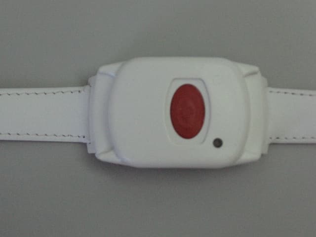
GSAWPK250
Jun 03, 2007PANIC WATCH
Equipment Class
DSC - Part 15 Security/Remote Control Transmitter
GSA5-RLE00125B
May 28, 2007LF Exciter
Equipment Class
DCD - Part 15 Low Power Transmitter Below 1705 kHz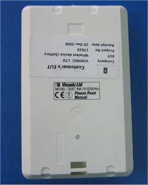
GSADUETAM
May 16, 2007Dual-Technology Microwave/PIR Intrusion Detector
Equipment Class
FDS - Part 15 Field Disturbance Sensor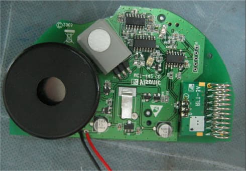
GSAMCT442
May 01, 2007Supervised Indoor Wireless CO Gas Detector
Equipment Class
DSC - Part 15 Security/Remote Control Transmitter