GSAMCM14015.231 Security / Remote Control Transmitter
Visonic Inc.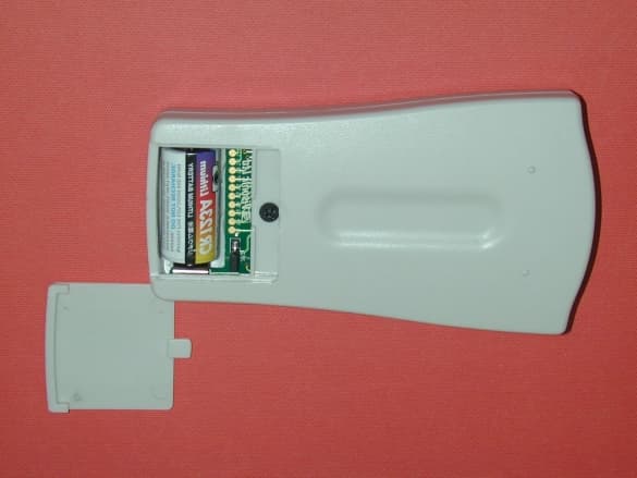
Click to zoom
Application Details
- Equipment Class
- DSC - Part 15 Security/Remote Control Transmitter
- Date of Grant
- Apr 14, 2002
- Application Purpose
- Original Equipment
- Date of Application
- Apr 14, 2002
- Equipment Note
- 15.231 Security / Remote Control Transmitter
- Frequency Range
- 315.00000000 - 315.00000000
- Company
- Visonic Inc.
- Country
- United States
Documents & Files
Document Text
Text extracted from the exhibit documents filed with the FCC. Open a document above to read the original.
Users Manual
DE2460U 1 MCM MCMMCM MCM- -- -140 140140 140 Wireless Remote Commander User’s Guide 1. INSTRODUCTION 1. INSTRODUCTION1. INSTRODUCTION 1. INSTRODUCTION The MCM-140 is a wireless remote control unit for the PowerMax system. It enables the user to arm/disarm the alarm system, to initiate emergency/fire/panic alarms, to perform one of the AUX (auxiliary) functions (see Note 3 in Section 6) and to turn lighting devices on and off. The keypad includes an RF transmitter that sends out a differently coded RF signal for each command. The main features of the MCM-140 are: • Automatic reporting of low battery voltage. • Visual indications by red/green/amber LED. • Keypad back lighting (selectable) • Various audible signals sounded by the buzzer in response to specific actions. • Automatic supervision messages at 60 minute intervals. • Long-life 3 VDC lithium battery. • Wall mounting option. • Friendly programming. The red LED lights during transmission. The amber LED lights during the programming process (and during transmission if battery voltage is low). The green LED lights upon each keystroke. LED Indications Description Symbol Blinks at a fast rate - - - - - - - Blinks at a slow rate _ _ _ _ _ Lights steadily (during transmission) ________ Figure 1 - External View Keypad Buzzer Sound Description Symbol Short single beep, upon pressing a key 2 short beeps, in the programming process (par. 4.3 & 4.5) Success (victory) melody Failure beep 2. SPECIFICATIONS 2. SPECIFICATIONS2. SPECIFICATIONS 2. SPECIFICATIONS Transmitted ID Type: PowerCode and CodeSecure PowerCode - Used for Lights 1-7, Light 8 (PGM controlled), Fire and Emergency functions CodeSecure - Used for Home arming, Away arming, Disarming, Aux and Panic functions Operating Frequency (MHz): 315, 433.9 and 868.95 Battery: 3 VDC, Lithium battery, CR123A Back light illumination: Selectable on/off Dimensions (HxWxD): 127 x 70 x 24 mm (5 x 2-3/4 x 31/32 in.) Operating Temperatures: 0 ° -49 ° C (32 ° -120 ° F) 3. MOUNTING AND BATTERY REPLACEMENT 3. MOUNTING AND BATTERY REPLACEMENT3. MOUNTING AND BATTERY REPLACEMENT 3. MOUNTING AND BATTERY REPLACEMENT Figure 2 - Mounting Figure 3 - Battery Replacement 2 DE2460U 4. PROGRAMMING 4. PROGRAMMING4. PROGRAMMING 4. PROGRAMMING 4.1 Programming Scope The following programming actions are possible: • Setting the master user (user #1) code. • Setting other user codes (users #2-8). • Allowing/forbidding quick arming of the keypad. • Muting/reactivating the keypad's buzzer. • Controlling the keypad's back-lighting. • Enabling/disabling the supervision/low battery reporting from the MCM-140. 4.2 Entering the Programming Mode The programming mode is accessible with the master code only (1 1 1 1 by default). The "#" key is used to enter and also to exit the programming mode. Entering the Programming Mode Action LED indication Buzzer response + Green LED blinks slowly until the master code is keyed * + [master code] (1111 by default) Amber LED blinks slowly during programming * (success melody) * Upon entering the programming mode, the success melody is heard and the amber LED starts blinking. Blinking will stop once you exit from this mode (by pressing "#" again) or upon time out during which no key is pressed. 2 short beeps are heard when the LED stops blinking. 4.3 Changing Master/User Codes To change the MCM-140 master and user codes, enter the programming mode (Par. 4.2) and proceed as follows: Action LED indication Buzzer response + [1-8] 1 Amber LED blinks + [new code] 2 Amber LED blinks quickly - (blinks slowly after success) (success melody) Notes 1. Enter user No. (1-8). User No. 1 is defined as the master user. 2. Master/user codes consist of 4-digits. Code "0000" is not valid. It can be used to erase the currently programmed code (when this action is performed, success melody is heard). 3. PowerMax user codes and MCM-140 user codes are different codes. 4.4 Restoring the Default Master Code If the master code is forgotten, it is possible to recall the factory default master code "1111". To ensure that this possibility is not misused by unauthorized people, a panic alarm is automatically transmitted to the PowerMax system when such an action is performed. To recall the default master code and prevent a panic alarm, set PowerMax to User Settings mode (see PowerMax Prog. Guide, Par. 1.2) and proceed as shown in the following illustration: 4.5 Special Programming Options Enter the programming mode (Par. 4.2) and proceed as follows: Desired function Press and then press: Quick arming 9 1 Buzzer control 9 2 + AWAY to enable (amber LED lights) Back lighting 9 3 + OFF to disable (amber LED blinks). Supervision / low battery reporting (only by using Fire button) 9 4 In both cases, the buzzer sounds twice, to indicate success. Notes: The supervision message will be sent once an hour. When there is Low Bat condition, trouble message will be displayed in the zone that was selected for the FIRE key. 5. ENROLLING THE MCM 5. ENROLLING THE MCM5. ENROLLING THE MCM 5. ENROLLING THE MCM- -- -140 TO THE POWERMAX 140 TO THE POWERMAX140 TO THE POWERMAX 140 TO THE POWERMAX 5.1 Enrolling CodeSecure Functions To enroll the MCM-140 CodeSecure functions (Home/Away arming, Disarming, Aux and Panic functions), proceed as follows: A. Enter PowerMax installer menu (see PowerMax Programming Guide, document DE5450P, par. 1.2). The PowerMax display will be "1. NEW INSTL CODE". B. Click <NEXT>. The enrolling mode will be selected and the PowerMax display will show: 2. ENROLLING C. Click <OK>. The PowerMax display will change to: ENROLL WL DEVICE D. Click <NEXT>. The PowerMax display will read: ENROLL KEYFOB E. Click <OK>. The PowerMax display will read: Keyfob No: _ F. Press the key on the PowerMax keypad that corresponds with the location (1-4) that you wish to enroll in (assuming that the PowerMax memory locations No. 1, 2, 3 and 4 are free - no keyfob has yet been enrolled to them). If, for example, you have pressed the "1" ke…
Text truncated - open the document above for the full version.
Block Diagram
• MCM-140 Block Diagram Microchip Processor Memory HCS301 Microchip Transmitter Module RFT3A Keyboard 3V Battery
Cover Letter(s)
April 15, 2002 American TCB 6731 Whittier Ave Suite C110 McLean, VA 22101 USA Subject: Application for certification of wireless remote commander, model: MCM 140 @ 315 MHz, FCC ID:GSAMCM140 Dear Gentlemen, Please find attached our application for certification of wireless remote commander, FCC ID: GSAMCM140, prepared in accordance with FCC Rules, parts 15 and 2. The product testing and this application for certification were performed by Hermon Laboratories, which is listed by FCC. Hermon Labs responsible person is Mr. Gonen Usishkin, tel: 011 972 4628 8001, fax:011 972 4628 8277, e-mail: [email protected] . Please send an invoice to Hermon Labs. We hope this application satisfies your requirements Yaacov Kotlicki Directing Manager Head Office 30 Habarzel Street Tel Aviv 69710 Israel Postal Address P.O.B. 22020 Tel Aviv 61220 Israel Tel 972 3 6456789 Fax 972 3 6456788
Cover Letter(s)
Subject: GSAMCM140 application Date: Wed, 24 Apr 2002 10:08:28 +0200 From: Valeria Mednikov <[email protected]> To: "'[email protected]'" <[email protected]> In reply to e-mail dated April 15, 2002 Dear Mr. Ward, Below are the answers to your questions. FCC ID: GSAMCM140. 1. The antenna is an integral part of the transmitter module RFT3A. Please find separate photographs of this module in "RFT 3A photographs" file, submitted via "Add to existing application", Internal photographs folder on April 24, 2002. This antenna can also be seen on photograph N.3 of "MCM internal photographs" file. In addition please find the data sheet for this antenna in "Coil antenna for RFT 3A" file, submitted via "Add to existing application", Additional information folder on April 24, 2002. 2. Please find the updated test report (with inserted Plots A3, A4 showing the duty cycle measurements, and duty cycle calculation below the plot), submitted via "Add to existing application" Test report folder on April 24, 2002. If necessary, I can send 10 plots more, which show duty cycle detailed calculation step by step. 3. The deactivation of transmitter after a two-second transmission is provided by software. Hope, you find these answers satisfactory. With great respect, Valeria
External Photos
MCM140 top view MCM140 bottom view
ID Label/Location Info
MCM 140 LABEL The identification label (material –polyester) is affixed on the device rear side. The drawing is shown on the next page.
Internal Photos
MCM140 internal view MCM140 PCB (first side) MCM140 PCB (second side)
Operational Description
DE2460U 1 MCM MCMMCM MCM- -- -140 140140 140 Wireless Remote Commander User’s Guide 1. INSTRODUCTION 1. INSTRODUCTION1. INSTRODUCTION 1. INSTRODUCTION The MCM-140 is a wireless remote control unit for the PowerMax system. It enables the user to arm/disarm the alarm system, to initiate emergency/fire/panic alarms, to perform one of the AUX (auxiliary) functions (see Note 3 in Section 6) and to turn lighting devices on and off. The keypad includes an RF transmitter that sends out a differently coded RF signal for each command. The main features of the MCM-140 are: • Automatic reporting of low battery voltage. • Visual indications by red/green/amber LED. • Keypad back lighting (selectable) • Various audible signals sounded by the buzzer in response to specific actions. • Automatic supervision messages at 60 minute intervals. • Long-life 3 VDC lithium battery. • Wall mounting option. • Friendly programming. The red LED lights during transmission. The amber LED lights during the programming process (and during transmission if battery voltage is low). The green LED lights upon each keystroke. LED Indications Description Symbol Blinks at a fast rate - - - - - - - Blinks at a slow rate _ _ _ _ _ Lights steadily (during transmission) ________ Figure 1 - External View Keypad Buzzer Sound Description Symbol Short single beep, upon pressing a key 2 short beeps, in the programming process (par. 4.3 & 4.5) Success (victory) melody Failure beep 2. SPECIFICATIONS 2. SPECIFICATIONS2. SPECIFICATIONS 2. SPECIFICATIONS Transmitted ID Type: PowerCode and CodeSecure PowerCode - Used for Lights 1-7, Light 8 (PGM controlled), Fire and Emergency functions CodeSecure - Used for Home arming, Away arming, Disarming, Aux and Panic functions Operating Frequency (MHz): 315, 433.9 and 868.95 Battery: 3 VDC, Lithium battery, CR123A Back light illumination: Selectable on/off Dimensions (HxWxD): 127 x 70 x 24 mm (5 x 2-3/4 x 31/32 in.) Operating Temperatures: 0 ° -49 ° C (32 ° -120 ° F) 3. MOUNTING AND BATTERY REPLACEMENT 3. MOUNTING AND BATTERY REPLACEMENT3. MOUNTING AND BATTERY REPLACEMENT 3. MOUNTING AND BATTERY REPLACEMENT Figure 2 - Mounting Figure 3 - Battery Replacement 2 DE2460U 4. PROGRAMMING 4. PROGRAMMING4. PROGRAMMING 4. PROGRAMMING 4.1 Programming Scope The following programming actions are possible: • Setting the master user (user #1) code. • Setting other user codes (users #2-8). • Allowing/forbidding quick arming of the keypad. • Muting/reactivating the keypad's buzzer. • Controlling the keypad's back-lighting. • Enabling/disabling the supervision/low battery reporting from the MCM-140. 4.2 Entering the Programming Mode The programming mode is accessible with the master code only (1 1 1 1 by default). The "#" key is used to enter and also to exit the programming mode. Entering the Programming Mode Action LED indication Buzzer response + Green LED blinks slowly until the master code is keyed * + [master code] (1111 by default) Amber LED blinks slowly during programming * (success melody) * Upon entering the programming mode, the success melody is heard and the amber LED starts blinking. Blinking will stop once you exit from this mode (by pressing "#" again) or upon time out during which no key is pressed. 2 short beeps are heard when the LED stops blinking. 4.3 Changing Master/User Codes To change the MCM-140 master and user codes, enter the programming mode (Par. 4.2) and proceed as follows: Action LED indication Buzzer response + [1-8] 1 Amber LED blinks + [new code] 2 Amber LED blinks quickly - (blinks slowly after success) (success melody) Notes 1. Enter user No. (1-8). User No. 1 is defined as the master user. 2. Master/user codes consist of 4-digits. Code "0000" is not valid. It can be used to erase the currently programmed code (when this action is performed, success melody is heard). 3. PowerMax user codes and MCM-140 user codes are different codes. 4.4 Restoring the Default Master Code If the master code is forgotten, it is possible to recall the factory default master code "1111". To ensure that this possibility is not misused by unauthorized people, a panic alarm is automatically transmitted to the PowerMax system when such an action is performed. To recall the default master code and prevent a panic alarm, set PowerMax to User Settings mode (see PowerMax Prog. Guide, Par. 1.2) and proceed as shown in the following illustration: 4.5 Special Programming Options Enter the programming mode (Par. 4.2) and proceed as follows: Desired function Press and then press: Quick arming 9 1 Buzzer control 9 2 + AWAY to enable (amber LED lights) Back lighting 9 3 + OFF to disable (amber LED blinks). Supervision / low battery reporting (only by using Fire button) 9 4 In both cases, the buzzer sounds twice, to indicate success. Notes: The supervision message will be sent once an hour. When there is Low Bat condition, trouble message will be displayed in the zone that was selected for the FIRE key. 5. ENROLLING THE MCM 5. ENROLLING THE MCM5. ENROLLING THE MCM 5. ENROLLING THE MCM- -- -140 TO THE POWERMAX 140 TO THE POWERMAX140 TO THE POWERMAX 140 TO THE POWERMAX 5.1 Enrolling CodeSecure Functions To enroll the MCM-140 CodeSecure functions (Home/Away arming, Disarming, Aux and Panic functions), proceed as follows: A. Enter PowerMax installer menu (see PowerMax Programming Guide, document DE5450P, par. 1.2). The PowerMax display will be "1. NEW INSTL CODE". B. Click <NEXT>. The enrolling mode will be selected and the PowerMax display will show: 2. ENROLLING C. Click <OK>. The PowerMax display will change to: ENROLL WL DEVICE D. Click <NEXT>. The PowerMax display will read: ENROLL KEYFOB E. Click <OK>. The PowerMax display will read: Keyfob No: _ F. Press the key on the PowerMax keypad that corresponds with the location (1-4) that you wish to enroll in (assuming that the PowerMax memory locations No. 1, 2, 3 and 4 are free - no keyfob has yet been enrolled to them). If, for example, you have pressed the "1" ke…
Text truncated - open the document above for the full version.
RF Exposure Info
Environmental evaluation and exposure limit according to FCC CFR 47part 1, §1.1307, §1.1310 Limit for power density for general population/uncontrolled exposure is 0.21 mW/cm 2 . P T The power density P (mW/cm 2 ) = ------------- , where 4 π r 2 P T is the maximum equivalent isotropically radiated power (EIRP). In our case P T is –15.23 dBm = 0.03 mW. 0.21(mW/cm 2 ) = 0.03 mW / 4π r 2 The minimum safe distance “r”, where RF exposure does not exceed FCC permissible limit, is 0.1 cm. r = sqrt(P T / (Px4 π )) = sqrt(0.03 / (0.21 x 4 x 3.14)) = 0.1 (cm). Hence, no safety hazard exists for human being.
Test Report
This report is in conformity with ISO/IEC 17025. The A2LA logo endorsement applies only to the test methods and the standards that are listed in the scope of Hermon Laboratories accreditation. The test results relate only to the items tested. This test report must not be reproduced in any form except in full with the approval of Hermon Laboratories Ltd. Page 1 of 24 Document ID: visrad_fcc.14997.doc Date of Issue: March 02 HERMON LABORATORIES Electrical Hermon Laboratories Ltd. P.O.Box 23 Binyamina 30550, Israel Tel.+972 66288001 Fax.+972 66288277 e-mail: [email protected] RADIO TEST REPORT ACCORDING TO 47 CFR Part 15 SUBPART C §15.231, §15.205, §15.209 and SUBPART B; RSS-210 Issue 5:2001; ICES-003 Issue 3:1997 for VISONIC Ltd. EQUIPMENT UNDER TEST: Wireless keypad MCM 140 @ 315 MHz Page 2 of 24 Document ID: visrad_fcc.14997.doc Date of Issue: March 02 HERMON LABORATORIES Contents CONTENTS.............................................................................................................................................................................. 2 1 PROJECT INFORMATION .............................................................................................................................................. 3 2 SUMMARY OF TESTS AND REQUIREMENTS .............................................................................................................. 4 3 EUT DESCRIPTION ......................................................................................................................................................... 6 3.1 G ENERAL DESCRIPTION ................................................................................................................................................ 6 3.2 EUT TEST CONFIGURATION .......................................................................................................................................... 6 3.3 T RANSMITTER DESCRIPTION .......................................................................................................................................... 7 4 TEST RESULTS............................................................................................................................................................... 8 4.1 B ANDWIDTH OF EMISSION ACCORDING TO § 15.231 ( C ) AND RSS-210 § 6.1.1( C ) ............................................................ 8 4.2 F IELD STRENGTH OF FUNDAMENTAL , § 15.231 AND RSS-210 § 6.1.1( B )......................................................................... 9 4.3 F IELD STRENGTH OF SPURIOUS RADIATION , § 15.231 AND RSS-210 § 6.1.1( B ) ............................................................. 10 4.4 U NINTENTIONAL RADIATED EMISSIONS TEST ACCORDING TO §15.109 AND ICES-003....................................................... 11 APPENDIX A - PLOTS .......................................................................................................................................................... 12 APPENDIX B – TEST SETUP PHOTOGRAPHS................................................................................................................... 20 APPENDIX C - TEST EQUIPMENT USED FOR TESTS ....................................................................................................... 22 APPENDIX D - GENERAL INFORMATION........................................................................................................................... 23 T EST FACILITY DESCRIPTION ................................................................................................................................................... 23 A BBREVIATIONS AND ACRONYMS ............................................................................................................................................. 23 S PECIFICATION REFERENCES .................................................................................................................................................. 23 FCC E QUIPMENT CODES AND DESCRIPTIONS ........................................................................................................................... 24 Page 3 of 24 Document ID: visrad_fcc.14997.doc Date of Issue: March 02 HERMON LABORATORIES 1 Project information Description of equipment under test Test items : Wireless keypad Manufacturer : Visonic Ltd. Brand name : MCM 140 Equipment serial number : Cat No 0-2460-1 Types (Models) : MCM 140 @ 315 MHz Equipment FCC code 1 : DSC Applicant information Applicant’s responsible person : Mr. Arick Elshtein Company : Visonic Ltd. Address : 27 Habarzel Street Postal code : 69710 City : Tel Aviv Country : Israel Telephone number : +972 3 6456714 Telefax number : +972 3 6456891 Test performance Project Number: : 14997 Location : Hermon Laboratories Receipt date : February 19, 2002 Test started : February 19, 2002 Test completed : March 12, 2002 Purpose of test : Apparatus compliance verification in accordance with emission requirements Test specification(s) : 47CFR Part 15, subpart C, §15.231, §15.205, §15.209, and subpart B §15.109; RSS-210 Issue 5: 2001 and ICES-003 Issue 3: 1997 1 FCC Equipment codes – see Appendix D Page 4 of 24 Document ID: visrad_fcc.14997.doc Date of Issue: March 02 HERMON LABORATORIES Hermon Laboratories Ltd. P.O.Box 23 Binyamina 30550, Israel Tel.+972 66288001 Fax.+972 66288277 e-mail: [email protected] 2 Summary of tests and requirements Parameter Subclause C NC NT NA Tested by Date tested Remarks Transmitter characteristics, §15.231 Periodic operation 15.231(a) X Refer to Installation instructions Bandwidth of emission 15.231(c) X Mr. M. Feldman, test engineer March 6, 2002 Field strength of fundamental 15.231(b)(2) X Mr. M. Feldman, test engineer March 6, 2002 Field strength of spurious radiation 15.231(b)(3) X Mr. Y. Neuman, test engineer; Mr. M. Feldman, test engineer March 12, 2002 Unintentional radiation, §15.107, §15.109 Conducted emissions 15.107 X Radiated emissions 15.109 X Refer to …
Text truncated - open the document above for the full version.
Test Report
This report is in conformity with ISO/IEC 17025. The A2LA logo endorsement applies only to the test methods and the standards that are listed in the scope of Hermon Laboratories accreditation. The test results relate only to the items tested. This test report must not be reproduced in any form except in full with the approval of Hermon Laboratories Ltd. Page 1 of 24 Document ID: visrad_fcc.14997.doc Date of Issue: March 02 HERMON LABORATORIES Electrical Hermon Laboratories Ltd. P.O.Box 23 Binyamina 30550, Israel Tel.+972 66288001 Fax.+972 66288277 e-mail: [email protected] RADIO TEST REPORT ACCORDING TO 47 CFR Part 15 SUBPART C §15.231, §15.205, §15.209 and SUBPART B; RSS-210 Issue 5:2001; ICES-003 Issue 3:1997 for VISONIC Ltd. EQUIPMENT UNDER TEST: Wireless keypad MCM 140 @ 315 MHz Page 2 of 24 Document ID: visrad_fcc.14997.doc Date of Issue: March 02 HERMON LABORATORIES Contents CONTENTS.............................................................................................................................................................................. 2 1 PROJECT INFORMATION .............................................................................................................................................. 3 2 SUMMARY OF TESTS AND REQUIREMENTS .............................................................................................................. 4 3 EUT DESCRIPTION ......................................................................................................................................................... 6 3.1 G ENERAL DESCRIPTION ................................................................................................................................................ 6 3.2 EUT TEST CONFIGURATION .......................................................................................................................................... 6 3.3 T RANSMITTER DESCRIPTION .......................................................................................................................................... 7 4 TEST RESULTS............................................................................................................................................................... 8 4.1 B ANDWIDTH OF EMISSION ACCORDING TO § 15.231 ( C ) AND RSS-210 § 6.1.1( C ) ............................................................ 8 4.2 F IELD STRENGTH OF FUNDAMENTAL , § 15.231 AND RSS-210 § 6.1.1( B )......................................................................... 9 4.3 F IELD STRENGTH OF SPURIOUS RADIATION , § 15.231 AND RSS-210 § 6.1.1( B ) ............................................................. 10 4.4 U NINTENTIONAL RADIATED EMISSIONS TEST ACCORDING TO §15.109 AND ICES-003....................................................... 11 APPENDIX A - PLOTS .......................................................................................................................................................... 12 APPENDIX B – TEST SETUP PHOTOGRAPHS................................................................................................................... 20 APPENDIX C - TEST EQUIPMENT USED FOR TESTS ....................................................................................................... 22 APPENDIX D - GENERAL INFORMATION........................................................................................................................... 23 T EST FACILITY DESCRIPTION ................................................................................................................................................... 23 A BBREVIATIONS AND ACRONYMS ............................................................................................................................................. 23 S PECIFICATION REFERENCES .................................................................................................................................................. 23 FCC E QUIPMENT CODES AND DESCRIPTIONS ........................................................................................................................... 24 Page 3 of 24 Document ID: visrad_fcc.14997.doc Date of Issue: March 02 HERMON LABORATORIES 1 Project information Description of equipment under test Test items : Wireless keypad Manufacturer : Visonic Ltd. Brand name : MCM 140 Equipment serial number : Cat No 0-2460-1 Types (Models) : MCM 140 @ 315 MHz Equipment FCC code 1 : DSC Applicant information Applicant’s responsible person : Mr. Arick Elshtein Company : Visonic Ltd. Address : 27 Habarzel Street Postal code : 69710 City : Tel Aviv Country : Israel Telephone number : +972 3 6456714 Telefax number : +972 3 6456891 Test performance Project Number: : 14997 Location : Hermon Laboratories Receipt date : February 19, 2002 Test started : February 19, 2002 Test completed : March 12, 2002 Purpose of test : Apparatus compliance verification in accordance with emission requirements Test specification(s) : 47CFR Part 15, subpart C, §15.231, §15.205, §15.209, and subpart B §15.109; RSS-210 Issue 5: 2001 and ICES-003 Issue 3: 1997 1 FCC Equipment codes – see Appendix D Page 4 of 24 Document ID: visrad_fcc.14997.doc Date of Issue: March 02 HERMON LABORATORIES Hermon Laboratories Ltd. P.O.Box 23 Binyamina 30550, Israel Tel.+972 66288001 Fax.+972 66288277 e-mail: [email protected] 2 Summary of tests and requirements Parameter Subclause C NC NT NA Tested by Date tested Remarks Transmitter characteristics, §15.231 Periodic operation 15.231(a) X Refer to Installation instructions Bandwidth of emission 15.231(c) X Mr. M. Feldman, test engineer March 6, 2002 Field strength of fundamental 15.231(b)(2) X Mr. M. Feldman, test engineer March 6, 2002 Field strength of spurious radiation 15.231(b)(3) X Mr. Y. Neuman, test engineer; Mr. M. Feldman, test engineer March 12, 2002 Unintentional radiation, §15.107, §15.109 Conducted emissions 15.107 X Radiated emissions 15.109 X Refer to …
Text truncated - open the document above for the full version.
Test Setup Photos
Radiated emission measureme nts Radiated emission measurements – EUT position
Contact Information
Applicant
Scott Jensen(Tec Manager)
860-243-0833
Technical Contact
Hermon LaboratoriesEdward Usoskin
[email protected]972-4-628-8001
Harakevet INdustrial Zone · Binymina · Israel
Non-Technical Contact
Visonic Ltd.Arick Eishtein
[email protected]972-3-645-6714
Test Firm
Hermon Laboratories Ltd.Alexander Usoskin
Technical Specifications
| # | Rule Parts | Frequency Range | Power Output |
|---|---|---|---|
| 1 | 15.231 | 315 MHz - 315 MHz | - |
Other Applications from Visonic Inc.

GSA5-BTC00433
Nov 14, 2007Infant Protection Bracelet
Equipment Class
DSC - Part 15 Security/Remote Control Transmitter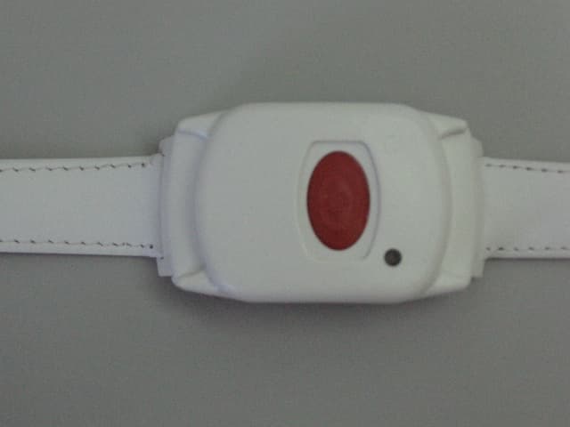
GSAWPK250
Jun 03, 2007PANIC WATCH
Equipment Class
DSC - Part 15 Security/Remote Control Transmitter
GSA5-RLE00125B
May 28, 2007LF Exciter
Equipment Class
DCD - Part 15 Low Power Transmitter Below 1705 kHz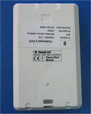
GSADUETAM
May 16, 2007Dual-Technology Microwave/PIR Intrusion Detector
Equipment Class
FDS - Part 15 Field Disturbance Sensor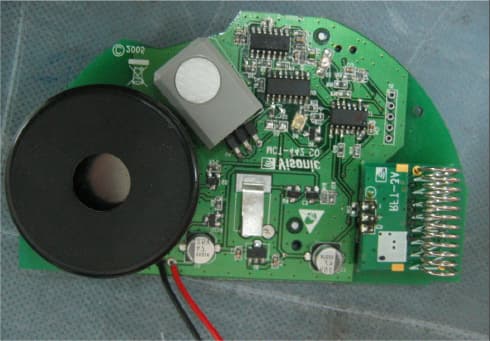
GSAMCT442
May 01, 2007Supervised Indoor Wireless CO Gas Detector
Equipment Class
DSC - Part 15 Security/Remote Control Transmitter