GSAMCS700Wireless Siren
Visonic Inc.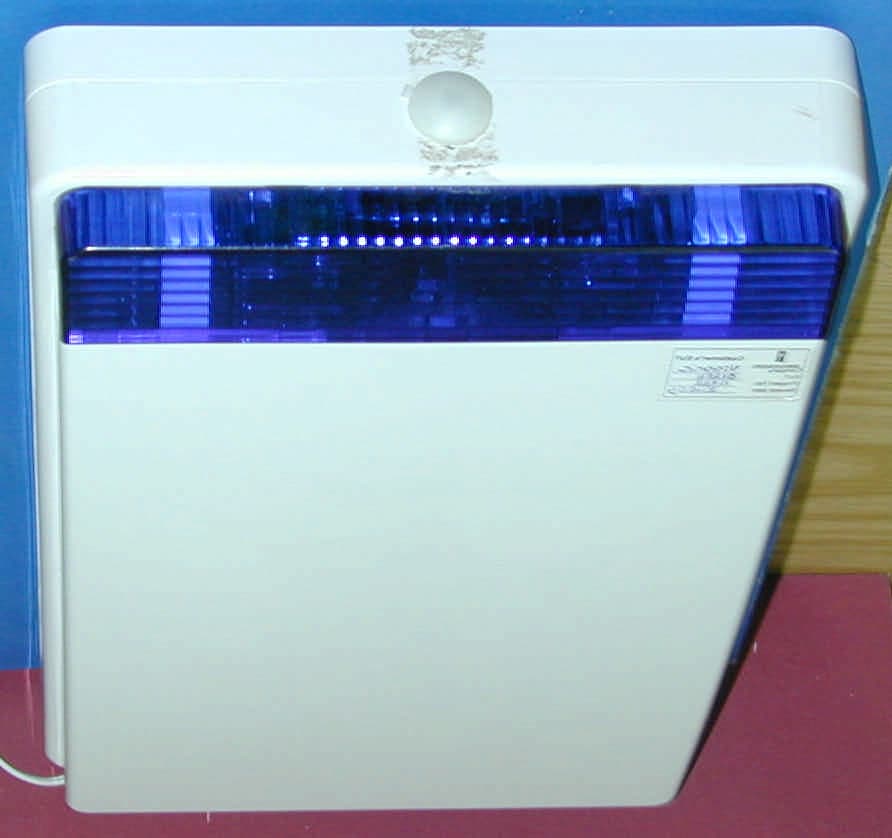
Click to zoom
Application Details
- Equipment Class
- DSR - Part 15 Remote Control/Security Device Transceiver
- Date of Grant
- May 11, 2004
- Application Purpose
- Original Equipment
- Date of Application
- May 11, 2004
- Equipment Note
- Wireless Siren
- Frequency Range
- 315.00000000 - 315.00000000
- Company
- Visonic Inc.
- Country
- United States
Documents & Files
Document Text
Text extracted from the exhibit documents filed with the FCC. Open a document above to read the original.
Users Manual
DE5420 1 MCS-700 Wireless Siren Installation Instructions 1. INTRODUCTION The MCS-700 is an indoor or outdoor wireless siren designed for installation in areas in which wiring action is difficult or impossible. The siren communicates with the PowerMax+ wireless alarm control system. When an identified activation command is received from the alarm system, the siren activates its sounder, activates its flash light (strobe light, every 1.5 seconds) and acknowledges its activation to the PowerMax+. The MCS-700 and the alarm control system should be located in the same house. MCS-700 Features • Designed for indoor or outdoor use The siren has double plastic cover for extra protection against rain and sun. • Distinguishable siren fire and burglar alarms Fire alarm: Alternating on/off alarm sound. Burglary alarm: Continuous high/low tone sweep. Note: The siren is activated for a predefined "Bell Time" (refer to PowerMax+ programming guide, par. 4.4) according to local authorities requirements. After this period, the siren sound stops. • Squawk indications High, mid or low siren squawk (beep) sounds can be used to indicate PowerMax+ arming (1 squawk) and disarming (2 squawks) by a keyfob (see PowerMax+ user's guide par. 7.13). • Strobe light When an identified activation command is received from the alarm system, the siren light flashes (every 1.5 seconds) until the PowerMax+ is disarmed. When AC power fails (the siren uses its backup battery) the strobe light is disabled. The siren can be purchased with red, blue, amber or transparent lens, according to the desired strobe light color. • AC Power indication LED When there is AC power supply, the red LED lights. When the siren uses its backup battery, the LED does not light. • Triple Tamper protection 3 tamper switches are included; one on side cover, second touching the mounting surface and third attached to the closure screw. • Rechargeable Ni-Mh backup battery Enables backup period of 12 hours (standby) / 15 min. (alarm), if small battery pack is used (supplied with the product), or 24 hours (standby) / 15 min. (alarm), if an optional large battery pack is used (2 small battery packs in parallel). Typical Initial charging time is 24 hours. When the battery voltage is low, low battery message is sent to the PowerMax+. Figure 1 - External View • 2-way full supervision The siren is fully supervised, 2-way communication device. It includes a receiver, to receive activation commands from the alarm system, and a transmitter, to periodically transmit its status signal to the alarm system. The transmitted signal strength can be measured during the installation (refer to PowerMax+ programming guide, section 9 – Diagnostic Test). • Self-test feature Upon pressing the MCS-700 self test switch for 3 seconds, the siren functional check is performed (low level sounds and strobe light indicate that that siren is serviceable). Wireless siren Hard wired detector Emergency pendant transmitter Smoke detector Universal perimeter protection detector Door or window open/close detector Motion detector Remote commander POWERMAX+ CONTROL PANEL Figure 2- Integration with the Alarm System 2. SPECIFICATIONS Siren Type: Piezo, 98dB SPL @ 1m, 1.8-2.3 kHz, sweep frequency 7Hz Power Supply: Indoor, limited power source, plug-in transformer (supplied with the siren): 120 VAC, 60 Hz / 9 VAC, 700 mA (in the U.S.A.), or 230 VAC, 50 Hz / 9 VAC, 700 mA. Backup Battery: Ni-Metal, 7.2V, 250mAh (small battery pack, supplied with the siren) or 500 mAh (optional large battery pack) Current Consumption: 13 mA ± 10% (standby), 370 mA ± 10% (operation) Compliance with Standards: EN 50131-1 (class 2), ETSI EN 300 220, FCC Part 15, IP55 Operating Frequency (MHz): 315, 433.92, 868.95, or 869.2625. Receiver and Transmitter ID Type: 24-bit Strobe Output: Pulsed @ 1.5 sec. Dimensions (LxWxD): 30 x 19 x 7 cm (11-13/16 x 7-1/2 x 2-3/4 in) Color: White (with red, blue, amber or transparent lens) Operating Temperature: -20°C to 65°C (-4°F to 149°F) 2 DE5420 3. INSTALLATION, TESTING AND ENROLLING Perform siren enrolling in PowerMax+ memory (see PowerMax+ prog. guide, section 2). When TRANSMIT NOW is displayed, momentarily press the siren Self-Test switch. 5 Battery ENROLLING Press Self-Test switch for 3 seconds. Verify that the siren sounds (low level sound) and that the strobe light flashes. 4 Battery SELF TEST Remove screw and remove cover 1 A.Connect 9VAC to POWER terminals. B.Connect the battery to the BAT connector. Battery 2 Mark and drill 4 holes (as desired) in mounting surface, fasten the siren to the surface with four 6 cm screws. 3 WARNING High voltage - do not remove printed board cover! 220/110 VAC 9VAC Figure 3 – Installation, Testing and Enrolling Notes a. Pressing the Self-Test switch for 3 seconds is used for testing the siren (by using low level sound) and its strobe light. b. Pressing the Self-Test switch momentarily is used to enroll the siren in the PowerMax+ memory (The PowerMax+ must recognize the siren unique identification code for command delivery and supervision). c. After the enrolling, close the siren cover and perform DIAGNOSTIC TEST, as described in PowerMax+ programming guide section 9. Interference Prevention This device complies with FCC Rules Part 15. Operation is subject to two conditions: (1) This device may not cause harmful interference, and (2) this device must accept any interference that may be received or that may cause undesired operation. The digital circuit of this device has been tested and found to comply with the limits for a Class B digital device, pursuant to Part15 of the FCC Rules. These limits are designed to provide reasonable protection against harmful interference in residential installations. This equipment generates, uses and can radiate radio frequency energy and, if not installed and used in accordance with the instructions, may cause harmful interference to radio and television reception. However, there is no guarantee that interference w…
Text truncated - open the document above for the full version.
Block Diagram
Microcontroler PIC16LF76T Piezo Flash Battery & low battery circuit 7.2 Vdc 4 MHz crystal Oscillator Tamper Switch Transmitter 315 Hz Power Supply Led (Red) Self Test Switch Power Supply circuit 9 VAC MCS-700 Wireless-Siren block diagram Receiver 315 Hz
Cover Letter(s)
March 2, 2004 American TCB 6731 Whittier Ave Suite C110 McLean, VA 22101 USA Subject: Application for certification of the wireless siren, model MCS700, FCC ID:GSAMCS700 Dear Gentlemen, Please find attached our application for certification of the wireless siren, model MCS700, FCC ID:GSAMCS700, prepared in accordance with FCC Rules, parts 15 and 2. The product testing and this application for certification were performed by Hermon Laboratories, which is listed by FCC. Hermon Labs responsible person is Mr. Edward Usoskin, tel: 011 972 4628 8001, fax:011 972 4628 8277, e-mail: [email protected]. Please send an invoice to Hermon Labs. We hope this application satisfies your requirements Yaacov Kotlicki Directing Manager Head Office 30 Habarzel Street Tel Aviv 69710 Israel Postal Address P.O.B. 22020 Tel Aviv 61220 Israel Tel 972 3 6456789 Fax 972 3 6456788
Cover Letter(s)
March 2, 2004 American TCB 6731 Whittier Ave Suite C110 McLean, VA 22101 USA Subject: Request for confidentiality for the wireless siren, model MCS700, FCC ID:GSAMCS700 Dear Gentlemen, We apply to you with request to withhold Visonic Ltd. trade secrets in Application for Certification for the wireless siren, model MCS700, FCC ID:GSAMCS700. These trade secrets can be found in the schematic diagram “Schematic_15722” (2 pages of this Application). Many thanks in advance. Yaacov Kotlicki Directing Manager Head Office 30 Habarzel Street Tel Aviv 69710 Israel Postal Address P.O.B. 22020 Tel Aviv 61220 Israel Tel 972 3 6456789 Fax 972 3 6456788
External Photos
FCC ID:GSAMCS700 Date: February 2004 Page 1 of 3 EXTERNAL PHOTOGRAPHS This document contains 2 photographs FCC ID:GSAMCS700 Date: February 2004 Page 2 of 3 Photograph No.1 Wireless siren General view FCC ID:GSAMCS700 Date: February 2004 Page 3 of 3 Photograph No.2 Wireless siren Rear side view
ID Label/Location Info
FCC ID:GSAMCS700 Label location Label with FCC ID:GSAMCS700 will be located at the bottom panel
Internal Photos
FCC ID:GSAMCS700 Date: February 2004 Page 1 of 8 INTERNAL PHOTOGRAPHS This document contains 7 photographs FCC ID:GSAMCS700 Date: February 2004 Page 2 of 8 Photograph No.1 Wireless siren Internal view FCC ID:GSAMCS700 Date: February 2004 Page 3 of 8 Photograph No.2 Wireless siren Internal view FCC ID:GSAMCS700 Date: February 2004 Page 4 of 8 Photograph No.3 Wireless siren PCB front view FCC ID:GSAMCS700 Date: February 2004 Page 5 of 8 Photograph No.4 Wireless siren Transmitter view FCC ID:GSAMCS700 Date: February 2004 Page 6 of 8 Photograph No.5 Wireless siren Transmitter view FCC ID:GSAMCS700 Date: February 2004 Page 7 of 8 Photograph No.6 Wireless siren Internal view FCC ID:GSAMCS700 Date: February 2004 Page 8 of 8 Photograph No.7 Wireless siren PCB rear side view
Operational Description
FCC ID:GSAMCS700 MCS-700 operational description The MCS-700 is an indoor or outdoor wireless siren of an intrusion detection system. The siren interacts with the Powermax+ intrusion/burglar alarm control panel. The siren activates its sounder, activates its flash light (strobe light, every 1.5 seconds) and acknowledges its activation to the PowerMax+. The Powermax+ alarm state is triggered by an intrusion detector sensing an intrusion and sends a message to the control panel. The control panel verifies the message if approved it send an alarm signal to the MCS 700. The MCS 700 has two "types" of similar messages whose duration is 100 msecond which are sent under different circumstances. 1. Every hour a supervision message is sent to the Powermax+ 2. Upon receipt of an alarm signal the MCS 700 returns a message received "hand shake signal". The difference between a message originating from the Powermax + and the MCS 700, is that the MCS 700 message consists of 72 bits while the one from the Powemax + is 88 bits. Note : the duration of the message is preprogrammed and can not be changed. The wireles siren trasmits a signal which consist of a message + preample. In th message , a bit 0 is 700usec ON and 350usec OFF, the message has 88 bits, the worst case is 83 zeros and 5 ones. The total duration of the preamble is 54.8 msec The total ON during the peamble is 38.8 msec
Test Report
This report is in conformity with ISO/IEC 17025. The A2LA logo endorsement applies only to the test methods and the standards that are listed in the scope of Hermon Laboratories accreditation. The test results relate only to the items tested. This test report must not be reproduced in any form except in full with the approval of Hermon Laboratories Ltd. Page 1 of 43 Document ID: VISRAD_FCC.15722.doc Date of Issue: February 2004 HERMON LABORATORIES Electrical Hermon Laboratories Ltd. P.O.Box 23 Binyamina 30500, Israel Tel.+972 6628 8001 Fax.+972 6628 8277 e-mail: [email protected] RADIO TEST REPORT According to 47 CFR Part 15 subpart C §15.231 and subpart B; RSS-210 Issue 5:2001; ICES-003 Issue 3:1997 for VISONIC Ltd. EQUIPMENT UNDER TEST: Wireless siren Model: MCS-700 Page 2 of 43 Document ID: VISRAD_FCC.15722.doc Date of Issue: February 2004 HERMON LABORATORIES Hermon Laboratories Ltd. P.O.Box 23 Binyamina 30500, Israel Tel.+972 6628 8001 Fax.+972 6628 8277 e-mail: [email protected] Contents CONTENTS........................................................................................................................................................................................................................................................2 1 PROJECT INFORMATION...............................................................................................................................................................................................................3 2 SUMMARY AND SIGNATURES.....................................................................................................................................................................................................4 3 EUT DESCRIPTION.............................................................................................................................................................................................................................5 3.1 GENERAL DESCRIPTION........................................................................................................................................................5 3.2 EUT TEST CONFIGURATION..................................................................................................................................................5 4 TEST RESULTS....................................................................................................................................................................................................................................6 4.1 FIELD STRENGTH OF FUNDAMENTAL, § 15.231 AND RSS-210 § 6.1.1(B).............................................................................6 4.2 FIELD STRENGTH OF SPURIOUS RADIATION, § 15.231 AND RSS-210 § 6.1.1(B)...................................................................8 4.3 BANDWIDTH OF EMISSION ACCORDING TO § 15.231(C) AND RSS-210 § 6.1.1(C)...............................................................10 4.4 UNINTENTIONAL RADIATED EMISSIONS TEST ACCORDING TO §15.109 AND ICES-003..........................................................11 4.5 CONDUCTED EMISSIONS TEST ACCORDING TO §15.107, 15.207.........................................................................................13 APPENDIX A - PLOTS................................................................................................................................................................................................................................15 APPENDIX B - TEST EQUIPMENT USED FOR TESTS................................................................................................................................................................32 APPENDIX C TEST EQUIPMENT CORRECTION FACTORS...................................................................................................................................................33 APPENDIX D - GENERAL INFORMATION........................................................................................................................................................................................43 TEST FACILITY DESCRIPTION...........................................................................................................................................................43 ABBREVIATIONS AND ACRONYMS.....................................................................................................................................................43 SPECIFICATION REFERENCES..........................................................................................................................................................43 Page 3 of 43 Document ID: VISRAD_FCC.15722.doc Date of Issue: February 2004 HERMON LABORATORIES Hermon Laboratories Ltd. P.O.Box 23 Binyamina 30500, Israel Tel.+972 6628 8001 Fax.+972 6628 8277 e-mail: [email protected] 1 Project information EUT attributes Test item : Wireless siren Serial number : W0904SN00001 Operating frequency : 315 MHz Type (Model) : MCS-700 Equipment FCC code : DSR Applicant information Applicant’s responsible person : Mr. Arick Elshtein, international standards department manager Applicant/Manufacturer : Visonic Ltd. Address : 30, Habarzel street City : Tel Aviv Postal code : 69710 Country : Israel Telephone number : +972 3645 6714 Telefax number : +972 3645 6891 Test details Project Number: : 15722 Location : Hermon Laboratories Receipt date : October 30, 2003 Test performed : November 16, 2003 Purpose of test : Apparatus compliance verification in accordance with emission requirements Test specification(s) : 47CFR Part 15, subpart C, §§15.231, 15.205, 15.207, 15.209, and subpart B §§15.107, 15.109; RSS-210 Issue 5: 2001 and ICES-003 Issue 3: 1997 Page 4 of 43 Document ID: VISRAD_FCC.15722.doc Date of Issue: February 2004 HERMON LABORATORIES Hermon Laboratories Ltd. P.O.Box 23 Binyamina 30500, Israel Tel.+972 6628 8001 Fax.+972 6628 8277 e-mail: [email protected] 2 Summary and…
Text truncated - open the document above for the full version.
Test Setup Photos
FCC ID:GSAMCS700 Date: February 2004 Page 1 of 5 SETUP PHOTOGRAPHS This document contains 4 photographs FCC ID:GSAMCS700 Date: February 2004 Page 2 of 5 Photograph No.1 Spurious radiated emissions measurement setup in the anechoic chamber with loop antenna FCC ID:GSAMCS700 Date: February 2004 Page 3 of 5 Photograph No.2 Radiated emissions measurement setup in the anechoic chamber with biconilog antenna FCC ID:GSAMCS700 Date: February 2004 Page 4 of 5 Photograph No.3 Radiated emissions measurement setup at the OATS with double ridged guide antenna FCC ID:GSAMCS700 Date: February 2004 Page 5 of 5 Photograph No.4 Conducted emissions measurement setup
Contact Information
Applicant
Scott Jensen(Tec Manager)
860-243-0833
Technical Contact
Hermon LaboratoriesEdward Usoskin
[email protected]+972-4628-8001
Harakevet Industrial Zone P.O. Box 23 · Binyamina · Israel
Test Firm
Hermon Laboratories Ltd.Alexander Usoskin
Technical Specifications
| # | Rule Parts | Frequency Range | Power Output |
|---|---|---|---|
| 1 | 15.231 | 315 MHz - 315 MHz | - |
Other Applications from Visonic Inc.

GSA5-BTC00433
Nov 14, 2007Infant Protection Bracelet
Equipment Class
DSC - Part 15 Security/Remote Control Transmitter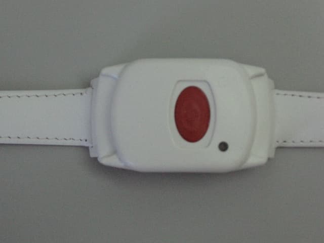
GSAWPK250
Jun 03, 2007PANIC WATCH
Equipment Class
DSC - Part 15 Security/Remote Control Transmitter
GSA5-RLE00125B
May 28, 2007LF Exciter
Equipment Class
DCD - Part 15 Low Power Transmitter Below 1705 kHz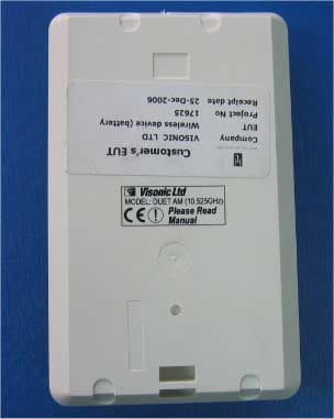
GSADUETAM
May 16, 2007Dual-Technology Microwave/PIR Intrusion Detector
Equipment Class
FDS - Part 15 Field Disturbance Sensor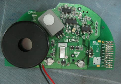
GSAMCT442
May 01, 2007Supervised Indoor Wireless CO Gas Detector
Equipment Class
DSC - Part 15 Security/Remote Control Transmitter