GSAMCT234Keyfob Transmitter
Visonic Inc.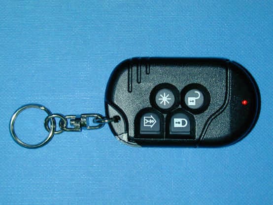
Click to zoom
Application Details
- Equipment Class
- DSC - Part 15 Security/Remote Control Transmitter
- Date of Grant
- Mar 03, 2004
- Application Purpose
- Original Equipment
- Date of Application
- Mar 03, 2004
- Equipment Note
- Keyfob Transmitter
- Frequency Range
- 315.00000000 - 315.00000000
- Company
- Visonic Inc.
- Country
- United States
Documents & Files
Document Text
Text extracted from the exhibit documents filed with the FCC. Open a document above to read the original.
Users Manual
DE2380 1 MCT-234 Wireless CodeSecure™ Keyfob Transmitter Installation Instructions 1. INTRODUCTION The MCT-234 is a miniature CodeSecure™ 4-button (4-function) transmitter, designed for use with advanced, high-security alarm and remote control systems such as the Visonic Ltd. UL-listed model PowerMax. For UL installations, use UL listed control panel, model PowerMax+ only. Transmission is initiated by pressing any one of the four recessed pushbuttons. Upon pressing a specific button, the MCT-234 transmits a CodeSecure™ digital sequence identifiable by compatible CodeSecure™ receivers, and a 4-bit function code associated with the button that was pressed. The next time a button is pressed, the MCT-234 will transmit a digital sequence that differs from the one used in the previous transmission and the respective function code. As a result, malicious “code grabbing” is virtually impossible. Operating power is obtained from an internal 12 V alkaline battery. A red LED lights during transmission as long as the battery voltage exceeds 8.6 V. If the LED flashes during transmission, the battery must be replaced without delay. In addition, a “low battery” report will be transmitted with the outgoing digital message. Compatible receivers are designed to identify this report and operate a corresponding output. Each transmitter is supplied with a small key ring. Figure 1. MCT-234 2. SPECIFICATIONS Frequency (MHz): 315, 433.92, 868.95, or other per local requirements (UL has only investigated at 315 MHz). Modulation: ASK (ON-OFF keying) Coding: 28-bit ID, 4-bit function code and 32-bit rolling code. Transmission Duration: Each button press causes transmission for up to 2 seconds. Power Supply: 12 V alkaline battery, type GP 23A or equivalent. For UL installations, use battery manufactured By GP. Current Consumption: 11 mA (during transmission) Battery Life Expectancy: 1 year (for typical use) Battery Supervision: Good battery - LED lights steadily upon transmission. Low battery - LED flickers upon transmission. Note: If transmission is still possible despite the battery condition, the unit will send a low battery signal to the receiver. Operating Temperature: 0° to 49°C (32° to 120°F). Dimensions: 53.5 x 31.5 x 12.5 mm (2-1/8 x 1-1/4 x 1/2 in.). Weight (including battery) : 21 g (3/4 oz). Color: Black Compliance with Standards: FCC Part 15, MPT1349 and Directive 1999/5/EC 3. TESTING AND MAINTENANCE 3.1 Testing a New Unit Since the MCT-234 is supplied with the battery already installed, the unit is practically ready to be tested. IMPORTANT! Before testing, "teach" the target receiver the ID code of the MCT-234, as instructed in the receiver's programming manual. A. Stand 3 m (10 ft) away from a target receiver (or wireless control panel) and press the MCT-234 button marked with a closed padlock icon. Verify that the transmit LED lights. B. Make sure that the receiver (or control panel) responds as programmed and as stated in the receiver’s instruction manual. C. Operate the transmitter from various locations within the area covered by the receiver to determine "dead" locations, where transmission is blocked by walls and large objects, or affected by structural materials. Note: If dead/marginal zones are a problem, relocating the receiver may improve the performance. 3.2 Replacing the Battery The battery should be replaced once every 12 months or upon observing that the LED flickers when transmitting. A replacement 12 V alkaline battery, such as Vinnic L1028, is available from hardware and electrical supply stores. For UL installations, use battery manufactured By GP. Replace the battery as follows: A. Use a small Phillips screwdriver to open the miniature screw at the back of the unit. Take care not to lose the screw. B. Put the unit down and extract the battery from its holder (see Figure 2). Figure 2. Inside View with Cover Removed Note: Make sure the elastic pad within the cover remains in place. Put it back in place if it falls off. C. Insert the new battery, observe polarity. D. Test the unit by momentarily pressing one of the transmit switches. The LED indicator should light. E. Put the cover back on and re-attach it with the screw. 3.3 Cleaning The transmitter may get dirty if touched with greasy fingers. Clean it only with a soft cloth or sponge moistened lightly with a mixture of water and mild detergent, and wipe it dry immediately. The use of abrasives of any kind is strictly forbidden. Also never use solvents such as kerosene, acetone or thinner. 2 DE2380 4. MISCELLANEOUS COMMENTS 4.1 Product Limitations Visonic Ltd. wireless systems are very reliable and are tested to high standards. However, due to their low transmitting power and limited range (required by FCC and other regulatory authorities), there are some limitations to be considered: A. Receivers may be blocked by radio signals occurring on or near their operating frequencies, regardless of the code selected. B. A receiver can only respond to one transmitted signal at a time. C. Wireless equipment should be tested regularly to determine whether there are sources of interference and to protect against faults. 4.2 Compliance with Standards This device complies with the essential requirements and provisions of Directive 1999/5/EC of the European Parliament and of the Council of 9 March 1999 on radio and telecommunications terminal equipment. The 315 MHz model of this device complies with Part 15 of the FCC Rules. Operation is subject to the following two conditions: (1) This device may not cause harmful interference, and (2) this device must accept any interference that may be received, including interference that may cause undesired operation. The user is cautioned that changes or modifications to the unit, not expressly approved by Visonic Ltd., could void the user's FCC authority to operate the equipment. 4.3 Frequency Allocations for Wireless Devices in European (EU) Countries • 433.92 MHz has no restriction in any EU member state…
Text truncated - open the document above for the full version.
Block Diagram
123450 CONFIDENTIAL This document contains information whichis proprietary to Visonic Ltd., Israel. Theuse, copy or dissemination of this materialfor any purpose other than that for which itis intended is prohibited with out the priorwritten consent of Visonic Ltd.Date Released: To Whom: Apx 2-1-3Designed:Drew:Updated:Approved: Name Date Product Name:Drawing Name: Signature Sheet No./of: Scale:Catalog No.:Drawing No.:File Name: Doc. Rev.: Upd ECOs MCT-234 (315MHZ) Block Diagram NAFTALI B.MARIA K. 17.01.01 1/1 0-2380-00F-238000F238000_315.VSD 0 LED INDICATOR PRINTED SMALL LOOP ANTENNA VCC ALKALINE BAT 12V 23A 4 x BUTTON MICROPROCESSOR HCS301 TRANSMITTION SAW 315 MHZ RESONATOR PINHAS I. 18.02.04 18.02.04 OPERATION DESCRIPTION:# SAW STABILIZED O.O.K. TRANSMITTER# ANTENNA: SMALL LOOP PRINTED ANTENNA
Cover Letter(s)
February 25, 2004 American TCB 6731 Whittier Ave Suite C110 McLean, VA 22101 USA Subject: Request for confidentiality for the keyfob transmitter, model MCT234, FCC ID: GSAMCT234 Dear Gentlemen, We apply to you with request to withhold Visonic Ltd. trade secrets in Application for Certification for the keyfob transmitter, model MCT234, FCC ID: GSAMCT234. These trade secrets can be found in the schematic diagram “Schematic_15815” (1 page of this Application). Many thanks in advance. Yaacov Kotlicki Directing Manager Head Office 30 Habarzel Street Tel Aviv 69710 Israel Postal Address P.O.B. 22020 Tel Aviv 61220 Israel Tel 972 3 6456789 Fax 972 3 6456788
External Photos
FCC ID:GSAMCT234 Date: February 2004 Page 1 of 3 EXTERNAL PHOTOGRAPHS This document contains 2 photographs FCC ID:GSAMCT234 Date: February 2004 Page 2 of 3 Photograph No.1 Keyfob transmitter Front view FCC ID:GSAMCT234 Date: February 2004 Page 3 of 3 Photograph No.2 Keyfob transmitter Rear side view
ID Label/Location Info
Label location Label FCC ID:GSAMCT234
Internal Photos
FCC ID:GSAMCT234 Date: February 2004 Page 1 of 4 INTERNAL PHOTOGRAPHS This document contains 3 photographs FCC ID:GSAMCT234 Date: February 2004 Page 2 of 4 Photograph No.1 Keyfob transmitter Internal view FCC ID:GSAMCT234 Date: February 2004 Page 3 of 4 Photograph No.2 Keyfob transmitter PCB front view FCC ID:GSAMCT234 Date: February 2004 Page 4 of 4 Photograph No.3 Keyfob transmitter PCB rear side view
Operational Description
FCC ID:GSAMCT234 MCT-234 Wireless CodeSecure™ Keyfob Transmitter Description 1.INTRODUCTION The MCT-234 is a miniature CodeSecure™ 4-button (4-function) transmitter, designed for use with advanced, high-security alarm and remote control systems such as the Visonic Ltd. UL-listed model PowerMax. For UL installations, use UL listed control panel, model PowerMax+ only. Transmission is initiated by pressing any one of the four recessed pushbuttons. Upon pressing a specific button, the MCT-234 transmits a CodeSecure™ digital sequence identifiable by compatible CodeSecure™ receivers, and a 4-bit function code associated with the button that was pressed. The next time a button is pressed, the MCT-234 will transmit a digital sequence that differs from the one used in the previous transmission and the respective function code. As a result, malicious “code grabbing” is virtually impossible. Operating power is obtained from an internal 12 V alkaline battery. A red LED lights during transmission as long as the battery voltage exceeds 8.6 V. If the LED flashes during transmission, the battery must be replaced without delay. In addition, a “low battery” report will be transmitted with the outgoing digital message. Compatible receivers are designed to identify this report and operate a corresponding output. Each transmitter is supplied with a small key ring. 2. SPECIFICATIONS Frequency (MHz): 315, 433.92, 868.95, or other per local requirements (UL has only investigated at 315 MHz). Modulation: ASK (ON-OFF keying) Coding: 28-bit ID, 4-bit function code and 32-bit rolling code. Transmission Duration: Each button press causes transmission for up to 2 seconds. Power Supply: 12 V alkaline battery, type GP 23A or equivalent. For UL installations, use battery manufactured By GP. Current Consumption: 11 mA (during transmission) Battery Life Expectancy: 1 year (for typical use) Battery Supervision: Good battery - LED lights steadily upon transmission. Low battery - LED flickers upon transmission.
Test Report
This report is in conformity with ISO/IEC 17025. The A2LA logo endorsement applies only to the test methods and the standards that are listed in the scope of Hermon Laboratories accreditation. The test results relate only to the items tested. This test report must not be reproduced in any form except in full with the approval of Hermon Laboratories Ltd. Page 1 of 39 Document ID: VISRAD_FCC.15815.doc Date of Issue: February 2004 HERMON LABORATORIES Electrical Hermon Laboratories Ltd. P.O.Box 23 Binyamina 30500, Israel Tel.+972 6628 8001 Fax.+972 6628 8277 e-mail: [email protected] RADIO TEST REPORT According to 47 CFR Part 15 subpart C §15.231 and subpart B; RSS-210 Issue 5:2001; ICES-003 Issue 3:1997 for VISONIC Ltd. EQUIPMENT UNDER TEST: Wireless CodeSecure keyfob transmitter Model: MCT-234 Page 2 of 39 Document ID: VISRAD_FCC.15815.doc Date of Issue: February 2004 HERMON LABORATORIES Hermon Laboratories Ltd. P.O.Box 23 Binyamina 30500, Israel Tel.+972 6628 8001 Fax.+972 6628 8277 e-mail: [email protected] Contents CONTENTS........................................................................................................................................................................................................................................................2 1 PROJECT INFORMATION...............................................................................................................................................................................................................3 2 SUMMARY AND SIGNATURES.....................................................................................................................................................................................................4 3 EUT DESCRIPTION.............................................................................................................................................................................................................................5 3.1 GENERAL DESCRIPTION........................................................................................................................................................5 4 TEST RESULTS....................................................................................................................................................................................................................................6 4.1 FIELD STRENGTH OF FUNDAMENTAL, § 15.231(B)(2) AND RSS-210 § 6.1.1(B)....................................................................6 4.2 FIELD STRENGTH OF SPURIOUS RADIATION, § 15.231 AND RSS-210 § 6.1.1(B)...................................................................8 4.3 BANDWIDTH OF EMISSION ACCORDING TO § 15.231(C) AND RSS-210 § 6.1.1(C).................................................................9 4.4 UNINTENTIONAL RADIATED EMISSIONS TEST ACCORDING TO §15.109 AND ICES-003..........................................................10 APPENDIX A - PLOTS................................................................................................................................................................................................................................11 APPENDIX B - TEST EQUIPMENT USED FOR TESTS................................................................................................................................................................27 APPENDIX C TEST EQUIPMENT CORRECTION FACTORS...................................................................................................................................................28 APPENDIX D - GENERAL INFORMATION........................................................................................................................................................................................39 TEST FACILITY DESCRIPTION...........................................................................................................................................................39 ABBREVIATIONS AND ACRONYMS.....................................................................................................................................................39 SPECIFICATION REFERENCES..........................................................................................................................................................39 Page 3 of 39 Document ID: VISRAD_FCC.15815.doc Date of Issue: February 2004 HERMON LABORATORIES Hermon Laboratories Ltd. P.O.Box 23 Binyamina 30500, Israel Tel.+972 6628 8001 Fax.+972 6628 8277 e-mail: [email protected] 1 Project information EUT attributes Test item : Wireless CodeSecure keyfob transmitter Operating frequency : 315 MHz Type (Model) : MCT-234 Equipment FCC code : DSC Applicant information Applicant’s responsible person : Mr. Arick Elshtein, international standards department manager Applicant/Manufacturer : Visonic Ltd. Address : 30, Habarzel street City : Tel Aviv Postal code : 69710 Country : Israel Telephone number : +972 3645 6714 Telefax number : +972 3645 6891 Test details Project Number: : 15815 Location : Hermon Laboratories Receipt date : January 27, 2004 Test performed : January 28, 2004 Purpose of test : Apparatus compliance verification in accordance with emission requirements Test specification(s) : 47CFR Part 15, subpart C, §§15.231, 15.205, 15.209, and subpart B §15.109; RSS-210 Issue 5: 2001 and ICES-003 Issue 3: 1997 Page 4 of 39 Document ID: VISRAD_FCC.15815.doc Date of Issue: February 2004 HERMON LABORATORIES Hermon Laboratories Ltd. P.O.Box 23 Binyamina 30500, Israel Tel.+972 6628 8001 Fax.+972 6628 8277 e-mail: [email protected] 2 Summary and signatures The EUT, keyfob transmitter, was tested according to FCC part 15 subparts B, C, and found to comply with the standard requirements. Test description Specification reference Tested by Date tested Test report paragraph Verdict Field strength of fundamental 15.231(b)(2) Mr. Y. Neuman, test engineer January 27, …
Text truncated - open the document above for the full version.
Test Report
FCC ID:GSAMCT234 Date: March 2004 Page 1 of 6 TEST DATA according to FCC part 15 §15.231 (a)(1) FCC ID:GSAMCT234 Date: March 2004 Page 2 of 6 MCT-234 keyfob transmitter functions description The 4 functions (buttons) of the keyfob, model MCT 234, are as follows: 1) ARM 2) DISARM 3) ARM HOME MODE and the push button marked * has a programmable function, its message is interpreted in different (programmed) ways in the received. The “Powermax+” control panel does not require more than 2 seconds to receive the instruction (ARM/DISARM etc), so all these transmissions durations are for the minimum required of 2 seconds for proper operation. Please see the attached manual in the specifications "Transmission Duration". The transmission duration data attached below in plots No.1 to No.4. FCC ID:GSAMCT234 Date: March 2004 Page 3 of 6 Plot No.1 Date/Time 3/10/2004 8:55:09 AM Title Periodic operation requirements EUT Model Number MCT-234 Analyzer Model Number HP8542E Analyzer Serial Number 262 Site Description OATS Operator Name Michael Lerman Customer Name Visonic Humidity 45% Temperature 21.1°C Air pressure 1022hPa Test equipment HL1430 Notes Arm Button Duration = 79.102 mSec FCC ID:GSAMCT234 Date: March 2004 Page 4 of 6 Plot No.2 Date/Time 3/10/2004 8:55:09 AM Title Periodic operation requirements EUT Model Number MCT-234 Analyzer Model Number HP8542E Analyzer Serial Number 262 Site Description OATS Operator Name Michael Lerman Customer Name Visonic Humidity 45% Temperature 21.1°C Air pressure 1022hPa Test equipment HL1430 Notes Disarm Button Duration = 87.113 mSec FCC ID:GSAMCT234 Date: March 2004 Page 5 of 6 Plot No.3 Date/Time 3/10/2004 8:55:09 AM Title Periodic operation requirements EUT Model Number MCT-234 Analyzer Model Number HP8542E Analyzer Serial Number 262 Site Description OATS Operator Name Michael Lerman Customer Name Visonic Humidity 45% Temperature 21.1°C Air pressure 1022hPa Test equipment HL1430 Notes Arm Home Button Duration = 64.083mSec FCC ID:GSAMCT234 Date: March 2004 Page 6 of 6 Plot No.4 Date/Time 3/10/2004 8:55:09 AM Title Periodic operation requirements EUT Model Number MCT-234 Analyzer Model Number HP8542E Analyzer Serial Number 262 Site Description OATS Operator Name Michael Lerman Customer Name Visonic Humidity 45% Temperature 21.1°C Air pressure 1022hPa Test equipment HL1430 Notes Information Button Duration =129.17 mSec
Test Setup Photos
FCC ID:GSAMCT234 Date: February 2004 Page 1 of 7 SETUP PHOTOGRAPHS This document contains 6 photographs FCC ID:GSAMCT234 Date: February 2004 Page 2 of 7 Photograph No.1 Spurious radiated emissions measurement setup in the anechoic chamber with loop antenna FCC ID:GSAMCT234 Date: February 2004 Page 3 of 7 Photograph No.2 Radiated emissions measurement setup in the anechoic chamber with biconical antenna FCC ID:GSAMCT234 Date: February 2004 Page 4 of 7 Photograph No.3 Radiated emissions measurement setup in the anechoic chamber with log periodic antenna FCC ID:GSAMCT234 Date: February 2004 Page 5 of 7 Photograph No.4 Radiated emissions measurement setup in the anechoic chamber with double ridged guide antenna FCC ID:GSAMCT234 Date: February 2004 Page 6 of 7 Photograph No.5 Radiated emissions measurement setup at the OATS with log periodic antenna FCC ID:GSAMCT234 Date: February 2004 Page 7 of 7 Photograph No.6 Radiated emissions measurement setup at the OATS with double ridged guide antenna
Contact Information
Applicant
Scott Jensen(Tec Manager)
860-243-0833
Technical Contact
Hermon LaboratoriesEdward Usoskin
[email protected]972 4 628-8001
Harakevet Industrial zone · Binyamina · Israel
Non-Technical Contact
Visonic Ltd.Arick Elshtein
[email protected]+972 3645 6714
Test Firm
Hermon Laboratories Ltd.Alexander Usoskin
Technical Specifications
| # | Rule Parts | Frequency Range | Power Output |
|---|---|---|---|
| 1 | 15.231 | 315 MHz - 315 MHz | - |
Other Applications from Visonic Inc.

GSA5-BTC00433
Nov 14, 2007Infant Protection Bracelet
Equipment Class
DSC - Part 15 Security/Remote Control Transmitter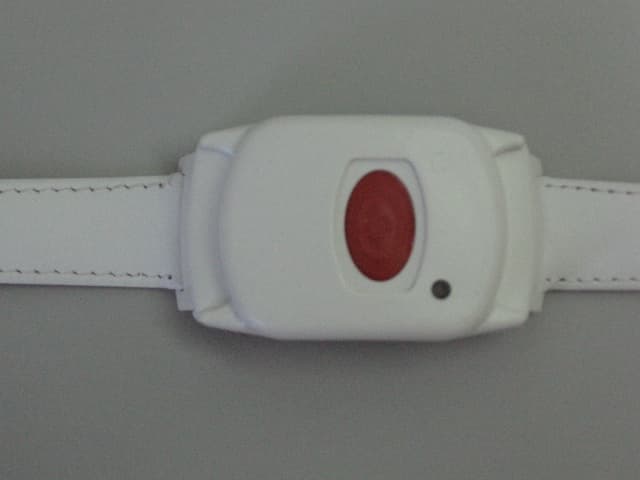
GSAWPK250
Jun 03, 2007PANIC WATCH
Equipment Class
DSC - Part 15 Security/Remote Control Transmitter
GSA5-RLE00125B
May 28, 2007LF Exciter
Equipment Class
DCD - Part 15 Low Power Transmitter Below 1705 kHz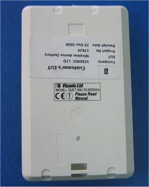
GSADUETAM
May 16, 2007Dual-Technology Microwave/PIR Intrusion Detector
Equipment Class
FDS - Part 15 Field Disturbance Sensor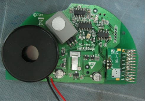
GSAMCT442
May 01, 2007Supervised Indoor Wireless CO Gas Detector
Equipment Class
DSC - Part 15 Security/Remote Control Transmitter