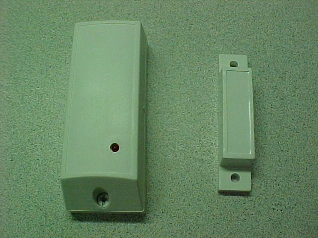
GSAMCT3023VSupervised PowerCode Magnetic Contact Transmitter
Visonic Inc.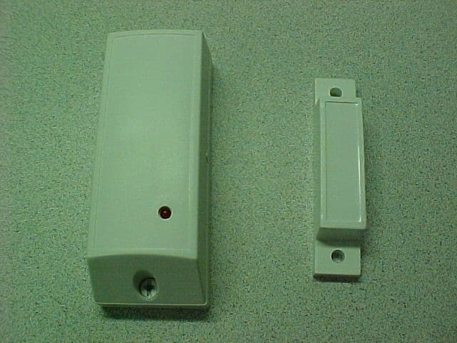
Click to zoom
Application Details
- Equipment Class
- DSC - Part 15 Security/Remote Control Transmitter
- Date of Grant
- Jan 05, 2003
- Application Purpose
- Original Equipment
- Date of Application
- Jan 05, 2003
- Equipment Note
- Supervised PowerCode Magnetic Contact Transmitter
- Frequency Range
- 315.00000000 - 315.00000000
- Company
- Visonic Inc.
- Country
- United States
Documents & Files
Document Text
Text extracted from the exhibit documents filed with the FCC. Open a document above to read the original.
Users Manual
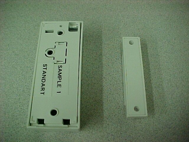
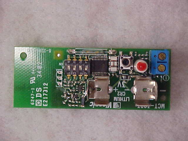
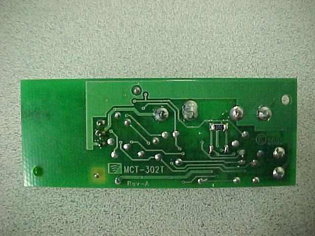
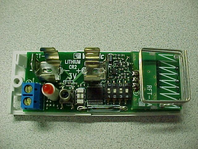
DE2281U1 MCT MCTMCT MCT-302 -302-302 -302 ( (( (3 33 3V) V)V) V) Supervised PowerCode Magnetic Contact Transmitter Installation Instructions 1 11 1. INTRODUCTION . INTRODUCTION. INTRODUCTION . INTRODUCTION The MCT-302 is a fully supervised, PowerCode magnetic contact transmitter. It features a built-in reed switch (that opens upon removal of a magnet placed near it) and an auxiliary hard-wired input, programmable as either N.C. or E.O.L., for use with additional sensors - pushbuttons, detectors, door contacts etc. An on-board DIP switch allows the installer to disable the magnet- operated reed switch if only the auxiliary input is needed. The reed switch and the auxiliary input behave as separate trans- mitters, although they trigger the same RF module into transmission. Each input has a unique 24-bit PowerCode ID, selected in the factory from over 16 million possible code combinations. Upon alarm, a digital message is transmitted, composed of the disturbed input’s PowerCode ID followed by various status and message-type markers. Alarm and other data are thus forwarded to the receiver. Since messages transmitted by the MCT-302 might collide with transmissions from other PowerCode transmitters, a "smart" anti- collision transmission sequence is used. The MCT-302 tamper switch is activated when the cover is removed. In a tamper situation, a message is transmitted from the reed switch input with the “tamper alert” marker ON. If the installer disables the reed switch, tamper is reported by the auxiliary input instead. A periodic supervision message, distinguished by a specific marker, is transmitted automatically from the reed switch input only (if enabled) or from the auxiliary input only (if the reed switch is disabled) once every 15 minutes (Europe) or once every 60 minutes (USA), or according to local standards. The target receiver is thus informed, at regular intervals, of the unit’s active participation in the system. An LED lights whenever alarm or tamper events are reported. The LED does not light while a supervision message is being transmitted. Operating power is obtained from an on-board 3 V Lithium Thionyl Chloride battery. A weak battery will cause a “low battery” marker to be added to any message transmitted. FUNCTION SELECTOR TRANSMITTER RF MODULE TAM PE R SWITCH AUX. INPUT TERMINALS 3V LITHIUM BATTERY REED SWITCH LED FLEXIBLE RETAINER P. C . B O A R D SUPPORTS NOTE: ONCE THE COVER IS TAKEN OFF AN ACTIVE MCT- 302 UNIT, A TAMPER MES- SAGE IS TRANSMITTED TO THE RECEIVER. SUBSEQUENT REMOVAL OF THE BATTERY PREVENTS TRANSMISSION OF “TAMPER RESTORE”, LEAVING THE RECEIVER IN PERMANENT TAMPER ALERT. TO AVOID THIS, PRESS THE TAMPER SWITCH AND MAINTAIN IT PRESSED WHILE YOU REMOVE THE BATTERY. Figure 1. MCT-302 with Cover Removed 2 22 2. SPECIFICATIONS . SPECIFICATIONS. SPECIFICATIONS . SPECIFICATIONS Frequency (MHz): 315, 433.92, 868.95 or other per local requirements (UL has only investigated at 315 MHz). Transmitter's ID Code: 24-bit digital word, over 16 million combinations, pulse width modulation. Overall Message Length: 36 bits Alarm Inputs: 2, one internal and one external, with a separate 24-bit transmitter ID each. Auxiliary Input Circuit Type: N.C. / E.O.L., selected with DIP switch E.O.L. Resistor Required: 47 kΩ Message Repetition: Repetitive transmission (once every 3 minutes) or one-shot, as selected with on-board DIP switch. Supervision: Signaling at 60-minute intervals or according to the local standard from the reed switch (if enabled) or from the aux. input (if the reed switch is disabled). Response to Tamper Event: Tamper report every 3 minutes (until the tamper switch is restored). Power Source: 3 V Lithium CR-2 type battery, Panasonic or equivalent. Battery Life Expectancy: 3 years (for typical use) Battery Supervision: Automatic transmission of battery condition data as part of any status report. Operating Temperature: 0°C to 49°C (32°F to 120°F). Dimensions: 81 x 22 x 23.5 mm (3-3/16 x 7/8 x 15/16 in.). Weight: MCT-302 (excluding battery): 34 g (1.2 oz) Magnet: 13 g (0.45 oz) Standards: Meets FCC Part 15, MPT1349 and Directive 1999/5/EC This device complies with Part 15 of the FCC Rules and RSS-210 of Industry and Science Canada. Operation is subject to the following two conditions: (1) This device may not cause harmful interference, and (2) this device must accept any interference received, including interference that may cause undesired operation. This device complies with the essential requirements and provisions of Directive 1999/5/EC of the European Parliament and of the Council of 9 March 1999 on radio and telecommunications terminal equipment. 3 33 3. INSTALLATION . INSTALLATION. INSTALLATION . INSTALLATION 3.1 Mounting It is highly recommended to attach the transmitter to the fixed frame and the magnet to the movable part (door or window), as shown in Figure 2. Make sure that the magnet is located not more than 6 mm (0.25 in.) from the transmitter’s marked side. A.Remove the case closure screw (Figure 3). B.Remove the unit’s cover as shown in Figure 4. C.Flex out the circuit board retainer (Figures 1 and 5) and detach the circuit board from the base. D.Hold the base against the mounting surface and mark the drilling points through the mounting holes (Figure 5). E.Drill the holes and fix the base to the wall using the 2 screws with countersunk heads supplied in the package . CAUTION! Screws with other type or size of head may short circuit the bottom side of the printed circuit board. F.Mount the magnet near the marked side of the MCT-302. G.Insert the edge of the P.C. board with the RF module into the edge supports, and press the other edge against the flexible retainer until it snaps home with a click. Figure 2. Mounting Example Figure 3. Removing the Case Closure Screw Figure 4. Separating the Cover from the Base 2DE2281U Figure 5. Base with P.C. Board Removed 3.2 Auxiliary Input Wiring Remember! If your application does not require the auxiliary input, …
Text truncated - open the document above for the full version.
Operational Description
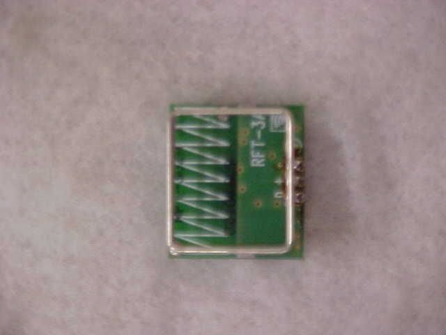
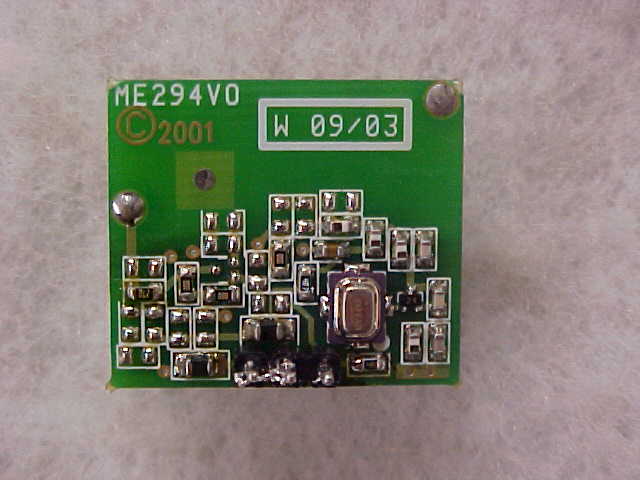
Operational Description Basically- the explanation is as follows: A trigger from the reed relay (when the magnet is removed), or from the external input, activates the transmitter, which emits (RF) an alarm message. The alarm message (36 bits long) consists of the transmitter ID and "Alarm" signal. If the battery is low, the alarm message will include also a "low battery" bit. If the tamper is operated, "tamper" signal is sent. 2. Every hour a short "supervision" message whose duration 580 msec is emitted (RF). The type of RF transmission in ON/OFF Keying, in other words every bit of the bit causes the RF carrier to be either fully ON or fully OFF. The RF part is an ASK (On/Off, Keying) transmitter with integral antenna. It has three inputs/ports :GND, VCC, DATA. A Colpits type oscillator with a SAW resonator creates the carrier of 315 Mhz. When only GND and VCC is supplied, the transmitter is in standby mode (does not oscillate). With every DATA pulse the Oscillator generate a carrier of 315MHz. This is ASK or ON/OFF keying modulation. From the Oscillator the RF signal is fed/driven through matching circuit to the integral antenna.
Parts List/Tune Up Info
CONFIDENTIAL Product Name: MCT-302 3V Catalog No.: E-2286-0 Document No.: EB-2286-1T PCB Rev.: A1 Edit By: MARIA K. Date.: 13/10/02 Approved by: PINHAS I. Page 1 of 1 This document contains information which is proprietary to Visonic Ltd. Israel. The use, copy or dissemination of this material for any purpose other than that which it is intended, is prohibited without the prior written consent of Visonic Ltd. Date Released: to whom: BILL OF MATERIAL S.M.D Side No.DescriptionDesManuf. Qty 1SMD TACT SWITCH 2.4mm,EQUIV.TO:TMP1DIPTRONIDTSM-644K-T/R1 2MINI 4 DIP SWI. SMD SAEL,EQUIV.TO: SW4DAILYWELDMR-04-T/R1 3SMD REED SWITCH 10-20 NI,EQUIV.TO: SW2SRCDEVIC/CELDUCFR2259 / IA31-14/35 AT 1 447 OHM RES. 0805R31 50 OHM RES. 0603R311 61 KOHM RES. 0603R121 710 KOHM RES. 0603R11,R42 8100 KOHM RES. 0603R81 947 KOHM RES. 0603R11 104.7 MOHM RES. 0603R61 11680 OHM RES. 0603R91 1210PF CAP. 0603C31 13100PF CAP. 0603C51 1410N CAP. 0603C2,C72 1547N CAP. 0603C41 16CERAMIC RES 4.00MHZ SMD,EQUIV.TO:X1MURATACSTCS4.00MG1 17MICRO CONTROL' SMD 04/SS,EQUIV.TO: U1MICROCHIPIC16LC711T-04/SS1 18DIODE CASE USM TE-17,EQUIV.TO:D1ROHM1SS3551 19STAND.VOLT.DETECTOR.2.7V,EQUIV.TO : U5TOREXXC61CC2702MR1 20T.CAP.3.3uF/6.3VC11 NDescriptionDesManuf. Q C.S. Side 1RED LED DIFF.D3mm RILL,EQUIV.TO:LD1LEDTECHLT-0341R-41-TAC1 2TERMINAL BLOCK 5MM/2P,EQUIV.TO:TB1NEXTRON301-021-16021 3PIN HEADER 3S 11.6mm,EQUIV.TO:#U2FULLCONNTEA-1000-10311 4PC 'A' & 'AA' BATT CLIP,EQUIV.TO:BAT,BAT1KISTONE922 5TRANSMITTER 315MHz,EQUIV.TO:U2VISONICRFT-302A (315)1
Parts List/Tune Up Info
CONFIDENTIAL Product Name: RFT-302 A 3V (315) Catalog No.: E-2348-0 Document No.: EB-2348-3T PCB Rev.: 3 Edit By: MARIA K. Date.: 30/10/02 Approved by: PINHAS I. Page 1 of 1 This document contains information which is proprietary to Visonic Ltd. Israel. The use, copy or dissemination of this material for any purpose other than that which it is intended, is prohibited without the prior written consent of Visonic Ltd. Date Released: to whom: BILL OF MATERIAL S.M.D Side No.DescriptionDesMan 10 OHM RES. 0603R10,R7,R8,R9TY OHMRMC 0603 1/16W 000J4 24.7 OHM RES. 0603R3TY OHMRMC 0603 1/16W 4R7J1 339 KOHM RES. 0603R1TY OHMRMC 0603 1/16W 333J1 43.9PF CAP. 0603C11SAMSUNGCL10 C3R9 B ANC1 56.8PF CAP. 0603C3SAMSUNGCL10 C6R8 C ANC1 622PF CAP. 0603C1SAMSUNGCL10C 220 J ANC1 747N CAP. 0603C2SAMSUNGCL10F473 ZBNC1 8SAW RES.315 MHz, EQUIV.TO:Q4MURATASAR UK315M00BXM0R111 9NPN TRAN. SMD , EQUIV.TO:Q1NECNE85619/ (2SC5006- T1) 1 10FERITTE CHIP SMD, EQUIV.TO:L2,L3CHILINSISBK201209T-601Y-S2 11SMD RFC COIL 15 NHY 0603, EQUIV.TO: L1TAIYO YUHK160815NJ1 12SMD RFC COIL 18 NHY 0603, EQUIV.TO: L8TAIYO YUHK160818NJ1 13RF COIL 100 NHY 5% 0603, EQUIV.TO: L9TAIYOYUDHK1608R10J-T1 14RF COIL 56 NHY 5% 0603, EQUIV.TO:L5TAIYO YUHK 1608 56NJ-T1 No.DescriptionDes Qty C.S. Side 1SQ ANTENNA 0.9X19X22A, EQUIV.TO:ANT2OCEAN SPSQ ANT 0.9X19X221
Test Report
Test Report No. R-9666-1 FCC ID: GSAMCT3023V APPLICANT Visonic, Inc. 10 Northwood Drive Bloomfield, CT 06002 MANUFACTURER Visonic, Inc. 10 Northwood Drive Bloomfield, CT 06002 TEST SPECIFICATION: FCC Rules and Regulations Part 15, Subpart C, Para. 15.231 TEST PROCEDURE: ANSI C63.4:2000 TEST SAMPLE DESCRIPTION BRANDNAME: Visonic, Inc. MODEL: MCT-302 3V TYPE: Pulsed Transmitter POWER REQUIREMENTS: 3 Volt Lithium, Type CR2 Battery FREQUENCY OF OPERATION: 315 MHz TESTS PERFORMED Para. 15.231(b), Radiated Emissions, Fundamental and Harmonics Para. 15.231(b), Radiated Emissions, Spurious Case Para. 15.35, Duty Cycle Determination Para. 15.231(c), Occupied Bandwidth REPORT OF MEASUREMENTS Applicant: Visonic, Inc. Device: Pulsed Transmitter FCC ID: GSAMCT3023V Power Requirements: 3 Volt Lithium, Type CR2 Battery Test Report No. R-9666-1 FCC ID: GSAMCT3023V Applicable Rule Section: Part 15, Subpart C, Section 15.231 Test Report No. R-9666-1 FCC ID: GSAMCT3023V REPORT OF MEASUREMENTS (continued) TEST RESULTS 15.231 (a): This device is used as a security transmitter. 15.231 (a)(1) & The transmitter is automatically operated and ceases transmission within 5 15.231(a)(2): seconds after deactivation. 15.231 (a)(3): The transmitter does perform periodic transmissions once every 60 minutes for a duration of 580 milliseconds. 15.231 (b): The fundamental field strength did not exceed 6040 μV/M (Average) at a test distance of 3 meters. In addition, the requirements of section 15.35 for averaging pulsed emissions and for limiting peak emissions were met. The field strength of harmonic and spurious emissions did not exceed 604 μV/M (AVERAGE). DETERMINATION OF FIELD STRENGTH LIMITS The field strength limits shown below are found in Section 15.231. Frequency Limit F1 = 260 3750 = L1 Fo = 315 Lo F2 = 470 12500 = L2 The formula below was utilized to determine the limits: Limit = L1 + [(Fo-F1)(L2-L1)/(F2-F1)] Solving yields: Fundamental Limit = 6040 μV/M (AVERAGE) @ 3 Meters Harmonic Limit = 604 μV/M (AVERAGE) @ 3 Meters Test Report No. R-9666-1 FCC ID: GSAMCT3023V REPORT OF MEASUREMENTS (continued) DUTY CYCLE DETERMINATION The unit’s RF output was directly coupled to the input of the spectrum analyzer. The analyzer was set for a frequency span of 0Hz. The sweep time was then adjusted in order to display one full pulse train. The transmitter on time was then summed and compared to the time for one full cycle in order to obtain the duty cycle.( See plots for additional information) Transmitter On Time = 21.05 milliseconds (maximum) Transmitter Cycle Time = 48 milliseconds Transmitter Duty Cycle = 43.8 % CALCULATION: 1 Large Pulse = 14.4 milliseconds 19 x 350 μs (small pulse) = 6.65 milliseconds 14.4 + 6.65 = 21.05 milliseconds Duty Cycle (21.05/48) = 43.8 % Correction Factor = 20 log(0.438) = -7.2 dB SPECTRUM ANALYZER DESENSITIZATION CONSIDERATIONS Due to the nature of the emissions being measured, care was taken to ensure that the resolution bandwidth of the spectrum analyzer was adequate to provide accurate measurements. The following formula was utilized: Setting pulse desensitization equal to zero and utilizing the minimum observed pulse width of 350μs yields a minimum required bandwidth of 1904.8 Hz. FCC specified bandwidths of 100kHz and 1MHz were utilized below and above 1GHz, respectively. Test Report No. R-9666-1 FCC ID: GSAMCT3023V GENERAL NOTES All readings were taken utilizing a peak detector function at a test distance of 3 meters. The duty cycle was applied to the peak readings in order to determine the average value of the emissions. The frequency range was scanned from 30 MHz to 3.2 GHz. All emissions not reported were more than 20 dB below the specified limit. Test Report No. R-9666-1 FCC ID: GSAMCT3023V EQUIPMENT LIST FCC15.231 Compliance Testing EN Type Manufacturer Description Model No. Cal Date Due Date 067 Open Area Test Site Retlif 3 Meter RNY 09/20/2000 09/20/2003 128 Double Ridged Guide Electro-Mechanics 1 GHz - 18 GHz 3105 06/07/2002 06/07/2003 133 Broadband Pre-Amplifier Electro-Metrics 10 kHz - 1 GHz, 26dB BPA-1000 06/11/2002 06/11/2003 141 Spectrum Analyzer Hewlett Packard 100 Hz - 40 GHz 8566B 07/17/2002 01/17/2003 141A Graphics Plotter Hewlett Packard N/A 7470A 03/05/2002 03/05/2003 141B Quasi-Peak Adaptor Hewlett Packard 100 Hz - 1 GHz 85650A 07/16/2002 01/16/2003 206B 6.0 dB Attenuator Texscan 0 - 1.0 GHz FP-50 - 6 dB 06/11/2002 06/11/2003 543 Preamplifier Hewlett Packard 1.0 GHz - 26.5 GHz 8449B 07/11/2002 07/11/2003 617 Interference Analyzer Electro-Metrics 10 kHz - 1 GHz EMC-30 08/23/2002 08/23/2003 767 Biconilog EMCO 26 - 2000 MHz 3142B 09/03/2002 09/03/2003 Test Report No. R-9132-1 FCC ID:GSAMCT3023V FCC 15.231(b) RADIATED EMISSIONS, FUNDAMENTAL & SPURIOUS CASE FCC 15.231(c) OCCUPIED BANDWIDTH Test Report No. R-9666-1 FCC ID:GSAMCT3023V FCC 15.35 DUTY CYCLE Test Report No. R-9666-1 FCC ID:GSAMCT3023V Test Setup Photograph
Contact Information
Applicant
Scott Jensen(Tec Manager)
860-243-0833
Technical Contact
Retlif Testing LaboratoriesThomas J Schneider
[email protected]631 737-1500
795 Marconi Ave. · Ronkonkoma, New York · United States
Non-Technical Contact
Retlif Testing LaboratoriesMichelle White
[email protected]631 737-1500
Test Firm
Retlif Testing LaboratoriesMichael Bozza
Technical Specifications
| # | Rule Parts | Frequency Range | Power Output |
|---|---|---|---|
| 1 | 15.231 | 315 MHz - 315 MHz | - |
Other Applications from Visonic Inc.

GSA5-BTC00433
Nov 14, 2007Infant Protection Bracelet
Equipment Class
DSC - Part 15 Security/Remote Control Transmitter
GSAWPK250
Jun 03, 2007PANIC WATCH
Equipment Class
DSC - Part 15 Security/Remote Control Transmitter
GSA5-RLE00125B
May 28, 2007LF Exciter
Equipment Class
DCD - Part 15 Low Power Transmitter Below 1705 kHz
GSADUETAM
May 16, 2007Dual-Technology Microwave/PIR Intrusion Detector
Equipment Class
FDS - Part 15 Field Disturbance Sensor
GSAMCT442
May 01, 2007Supervised Indoor Wireless CO Gas Detector
Equipment Class
DSC - Part 15 Security/Remote Control Transmitter