GSAMCT425Photoelectric Smoke Detector
Visonic Inc.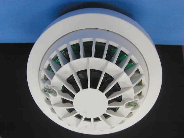
Click to zoom
Application Details
- Equipment Class
- DSC - Part 15 Security/Remote Control Transmitter
- Date of Grant
- May 27, 2003
- Application Purpose
- Original Equipment
- Date of Application
- May 27, 2003
- Equipment Note
- Photoelectric Smoke Detector
- Frequency Range
- 315.00000000 - 315.00000000
- Company
- Visonic Inc.
- Country
- United States
Documents & Files
Document Text
Text extracted from the exhibit documents filed with the FCC. Open a document above to read the original.
Users Manual
DE36421 MCT MCTMCT MCT-425 -425-425 -425 Supervised Wireless PowerCode Smoke Detector Installation Instructions 1. DESCRIPTION AND APPLICATIONS The MCT-425 is photoelectric smoke detector designed to sense smoke, but not gas, heat or flame and fitted with a Power- Code-type UHF transmitter. It provides early warning of developing fire by sounding an alarm with its built-in alarm horn, and by transmitting a coded alarm signal to a PowerCode receiver or to a compatible wireless alarm control panel. It must be borne in mind, though, that effective pre-warning of fire accidents is only possible if the detector is located, installed and maintained properly as described in this manual. WARNING: This smoke detector is designed for use in a single residential unit only, which means that it should be used inside a single family home or apartment. It is not meant to be used in lobbies, hallways, basements or another apartment in multi-family buildings, unless there are already working detectors in each family unit. Smoke detectors, placed in common areas outside the individual living unit, such as on porches or in hallways, may not provide early warning to residents. In multi-family buildings, each family living unit should obtain its own detector. WARNING: This detector is not meant to be used in non-residential buildings. Warehouses, industrial or commercial buildings and special purpose non- residential buildings require special fire detection and alarm systems. This detector alone is not a suitable substitute for complete fire detection systems for places where many people live or work, such as hotels or motels. The same is true of dormitories, hospitals, nursing homes or group homes of any kind, even if they were Figure 1. General View once single family homes. Please refer to NFPA 101, the Life Safety Code, NFPA71, 72A, 72B, 72C, 72D and 72E for smoke detector requirements for fire protection in buildings not defined as "households". WARNING: This detector, if used as a stand-alone unit, will not alert people who are hard of hearing. 2 22 2. INSTALLATION SUMMARY . INSTALLATION SUMMARY. INSTALLATION SUMMARY . INSTALLATION SUMMARY 2.1 Disassembly Separate the unit from its mounting bracket as shown in Figure 2. Figure 2. Separating the MCT-425 from its Bracket 2.2 Setting the Function Switch The MCT-425 has a 4-position DIP switch function selector (see Figure 3). The switch levers are numbered 1 to 4, and each switch allows you to select one of two options. Set the function switches as desired. The ON position is indicated on the switch body. Table 1. Function selector settings Sw-MarkingPos.Selected OptionDefault SW-1 LEDON OFF LED will light upon transmission LED is disabled ON SW-2 RSTON OFF “Restore” events reported “Restore” events not reported ON SW-3 TRRON OFF Do not use! Always OFF OFF SW-4 BATON OFF Do not use! Alkaline or Lithium battery is being used OFF Battery cover Figure 3. Function Selector and Battery Cover 2.3 Definitions of LED Light and Buzzer The red and yellow LED light and buzzer turn on and/or off to indicate various situations. There are several LED light and buzzer operations. A.When the red LED flashes every 30 seconds, this means power on, i.e., the detector is energized. B.When the red LED flashes and the buzzer beeps intermittently, this means alarm for potential smoke hazard. C.When the red LED flashes together with buzzer beeps for every 30 seconds with temporal tone 0.5 second on and 0.5 second off intermittently, this means battery power is low. D.The yellow LED turns on every time an RF signal is transmitted to the control panel. 2.4 Battery Connection and Initial Test CAUTION: The MCT-425 is fitted with cover latches that will prevent the cover from closing if there is no battery inside. The smoke detector is supplied with a 9V battery seated within its holder but insulated from the battery terminals. BRACKETDETECTOR ❷ Rotate Unit Counter- Clockwise ❶ Seize Bracket ❸ Pull Away From Bracket Test Button TAMPER 2DE3642 A.Connect the snap-on battery clip to the battery terminals. The clip will not fit if the contacts are reversed, but take care not to make a prolonged reverse contact - the battery will discharge rapidly through the built in protection diode! Note: When the battery first makes contact, the alarm horn may sound for one second. This indicates that the battery is connected properly. B.Push the battery firmly in until it is seated tightly within the holder, with the snap-on clip pressed against the contact springs. C.Close the cover, then press the test button for about 5 seconds until the horn sounds two sequences of a loud 3-beep alarm. This means that the smoke detection section is working properly. 2.5 Resetting the Transmitter Module and Enrolling its PowerCode ID A rear tamper protection switch is mounted under the PC board. The tamper switch actuator, extending through a hole in the base (see Figure 4), is pressed against the bracket when the unit is attached to the bracket. Removal of the unit from the bracket will cause the switch contacts to open, creating a tamper event, which will be reported by the transmitter to the control panel. Battery cover Figure 4. Rear Tamper Refer to the control panel’s installation instructions and follow the procedure given there for enrolling transmitter IDs in the control panel's memory. When required to initiate a transmission for enrollment, press the smoke detector’s test button until the built-in horn sounds, or press the tamper switch. Note: It is much easier to carry out this operation while holding the MCT-425 in your hand, close to the control panel. 2.6 Mounting the Bracket in Place Read Section 4 in this manual first, then decide where to install a detector. Refer to Figures 5 and 6 and proceed as follows: Figure 5. Aligning the Bracket Figure 6. Mounting the Bracket A . At the location where you intend to install the detector, draw a horizontal line six inches long. B . Remove the mounting bracke…
Text truncated - open the document above for the full version.
Block Diagram
123450 CONFIDENTIAL This document contains information whichis proprietary to Visonic Ltd., Israel. Theuse, copy or dissemination of this materialfor any purpose other than that for which itis intended is prohibited with out the priorwritten consent of Visonic Ltd.Date Released: To Whom: Apx 2-1-3Designed:Drew:Updated:Approved: Name Date Product Name:Drawing Name: Signature Sheet No./of: Scale:Catalog No.:Drawing No.:File Name: Doc. Rev.: Upd ECOs MCT-425Block Diagram RONEN D.MICKY L. 20.05.03 1/1 0-3642-10F-3642-1-00F364210.VSD 0 smoke detector chip microcontroller pic16c711 alarm led (red) buzzer photoelectric smoke sensor RC oscillator test switch low battery circuit 4Mhz crystal oscillator tamper transmission led (yellow) dipswitch 1 to 4 power supply circuit 9v battery MCT-425 smoke detector block diagram Transmitter 433 Hz315 Hz868 Hz869 Hz
Cover Letter(s)
May 20, 2003 American TCB 6731 Whittier Ave Suite C110 McLean, VA 22101 USA Subject: Request for confidentiality for wireless smoke detector, model: MCT-425, FCC ID: GSAMCT425 Dear Gentlemen, We apply to you with request to withhold Visonic Ltd. trade secrets in Application for Certification for FCC ID: GSAMCT425. These trade secrets can be found in the transmitter schematic diagrams (4 pages of this Application). Many thanks in advance. Yaacov Kotlicki Directing Manager Head Office 30 Habarzel Street Tel Aviv 69710 Israel Postal Address P.O.B. 22020 Tel Aviv 61220 Israel Tel 972 3 6456789 Fax 972 3 6456788
Cover Letter(s)
May 20, 2003 American TCB 6731 Whittier Ave Suite C110 McLean, VA 22101 USA Subject: Application for certification of wireless smoke detector, model: MCT-425, FCC ID:GSAMCT425 Dear Gentlemen, Please find attached our application for certification of wireless smoke detector, FCC ID: GSAMCT425, prepared in accordance with FCC Rules, parts 15 and 2. The product testing and this application for certification were performed by Hermon Laboratories, which is listed by FCC. Hermon Labs responsible person is Mr. Gonen Usishkin, tel: 011 972 4628 8001, fax:011 972 4628 8277, e-mail: [email protected] . Please send an invoice to Hermon Labs. We hope this application satisfies your requirements Yaacov Kotlicki Directing Manager Head Office 30 Habarzel Street Tel Aviv 69710 Israel Postal Address P.O.B. 22020 Tel Aviv 61220 Israel Tel 972 3 6456789 Fax 972 3 6456788
External Photos
Page 1 of 4 MCT-425 EXTERNAL PHOTOGRAPHS This document contains 3 photographs Page 2 of 4 Photograph No.1 MCT-425 front view Page 3 of 4 Photograph No.2 MCT-425 side view Page 4 of 4 Photograph No.3 MCT-425 rear view
ID Label/Location Info
The identification label (material –polyester) is affixed on the device rear side.
Test Report
This report is in conformity with ISO/IEC 17025. The A2LA logo endorsement applies only to the test methods and the standards that are listed in the scope of Hermon Laboratories accreditation. The test results relate only to the items tested. This test report must not be reproduced in any form except in full with the approval of Hermon Laboratories Ltd. Page 1 of 53 Document ID: visrad_fcc.15461 Date of Issue: May 2003 HERMON LABORATORIES Electrical Hermon Laboratories Ltd. P.O.Box 23 Binyamina 30550, Israel Tel.+972 66288001 Fax.+972 66288277 e-mail: [email protected] RADIO TEST REPORT ACCORDING TO 47 CFR Part 15 SUBPART C §15.231, §15.205, §15.209 and SUBPART B; RSS-210 Issue 5:2001; ICES-003 Issue 3:1997 for VISONIC Ltd. EQUIPMENT UNDER TEST: Supervised wireless Power Code smoke detector Model: MCT-425 @ 315 MHz Page 2 of 53 Document ID: visrad_fcc.15461 Date of Issue: May 2003 HERMON LABORATORIES Contents CONTENTS.......................................................................................................................................................................................2 1 PROJECT INFORMATION......................................................................................................................................................3 2 SUMMARY OF TESTS AND REQUIREMENTS....................................................................................................................4 3 EUT DESCRIPTION.................................................................................................................................................................6 3.1 GENERAL DESCRIPTION........................................................................................................................................................6 3.2 EUT TEST CONFIGURATION..................................................................................................................................................6 3.3 TRANSMITTER DESCRIPTION.................................................................................................................................................7 4 TEST RESULTS.......................................................................................................................................................................8 4.1 BANDWIDTH OF EMISSION ACCORDING TO § 15.231 (C) AND RSS-210 § 6.1.1(C)................................................................8 4.2 FIELD STRENGTH OF FUNDAMENTAL, § 15.231 AND RSS-210 § 6.1.1(B).............................................................................9 4.3 FIELD STRENGTH OF SPURIOUS RADIATION, § 15.231 AND RSS-210 § 6.1.1(B).................................................................10 4.4 UNINTENTIONAL RADIATED EMISSIONS TEST ACCORDING TO §15.109 AND ICES-003..........................................................11 APPENDIX A - PLOTS...................................................................................................................................................................12 APPENDIX B – TEST SETUP PHOTOGRAPHS.........................................................................................................................34 APPENDIX C - TEST EQUIPMENT USED FOR TESTS.............................................................................................................41 APPENDIX D - GENERAL INFORMATION..................................................................................................................................52 TEST FACILITY DESCRIPTION...........................................................................................................................................................52 ABBREVIATIONS AND ACRONYMS.....................................................................................................................................................52 SPECIFICATION REFERENCES..........................................................................................................................................................52 FCC EQUIPMENT CODES AND DESCRIPTIONS..................................................................................................................................53 Page 3 of 53 Document ID: visrad_fcc.15461 Date of Issue: May 2003 HERMON LABORATORIES 1 Project information Description of equipment under test Test items : Supervised wireless Power Code smoke detector Manufacturer : Visonic Ltd. Types (Models) : MCT-425 @ 315 MHz Equipment FCC code 1 : DSC Applicant information Applicant’s responsible person : Mr. Arick Elshtein, project manager Company : Visonic Ltd. Address : 27 Habarzel Street Postal code : 69710 City : Tel Aviv Country : Israel Telephone number : +972 3 6456714 Telefax number : +972 3 6456891 Test performance Project Number: : 15461 Location : Hermon Laboratories Receipt date : March 13, 2003 Test performed : March 20, 2003 Purpose of test : Apparatus compliance verification in accordance with emission requirements Test specification(s) : 47CFR Part 15, subpart C, §15.231, §15.205, §15.209, and subpart B §15.109; RSS-210 Issue 5: 2001 and ICES-003 Issue 3: 1997 1 FCC Equipment codes – see Appendix D Page 4 of 53 Document ID: visrad_fcc.15461 Date of Issue: May 2003 HERMON LABORATORIES Hermon Laboratories Ltd. P.O.Box 23 Binyamina 30550, Israel Tel.+972 66288001 Fax.+972 66288277 e-mail: [email protected] 2 Summary of tests and requirements Parameter Subclause C NC NT NA Tested by Date tested Remarks Transmitter characteristics, §15.231 Periodic operation 15.231(a) X Refer to Installation instructions Bandwidth of emission 15.231(c) X Mr. A. Troupianski, test engineer March 18, 2003 Field strength of fundamental 15.231(b)(2) X Mr. Y. Neuman, test engineer March 13, 2003 Field strength of spurious radiation 15.231(b)(3) X Mr. A. Troupianski, test engineer March 16, 19, 2003 Unintentional radiation, §15.107, §15.109 Conducted emissions 15.107 X Rad…
Text truncated - open the document above for the full version.
Test Setup Photos
Page 1 of 8 MCT-425 TEST SETUP PHOTOGRAPHS This document contains 7 photographs Page 2 of 8 Photograph 1 Spurious emission measurement setup in 9 kHz – 30 MHz range, Loop antenna in vertical polarization Page 3 of 8 Photograph 2 Spurious emission measurement setup in 30 – 200 MHz range, Biconical antenna in horizontal polarization Page 4 of 8 Photograph 3 Spurious emission measurement setup in 200 – 1000 MHz range, Log periodic antenna in vertical polarization Page 5 of 8 Photograph 4 Spurious emission measurement setup in 1 – 3.2 GHz range, Horn antenna in horizontal polarization Page 6 of 8 Photograph 5 20 dB bandwidth measurement setup, Log periodic antenna in vertical polarization Page 7 of 8 Photograph 6 Harmonics emission measurement setup, Horn antenna in vertical polarization Page 8 of 8 Photograph 7 Unintentional radiated emission measurement setup in 30 – 2000 MHz range, Biconilog antenna in vertical polarization
Contact Information
Applicant
Scott Jensen(Tec Manager)
860-243-0833
Technical Contact
Hermon LaboratoriesGonen Usishkin
[email protected]972-4-628-8001
Harakevey Industrial zone · Binyamina · Israel
Test Firm
Hermon Laboratories Ltd.Alexander Usoskin
Technical Specifications
| # | Rule Parts | Frequency Range | Power Output |
|---|---|---|---|
| 1 | 15.231 | 315 MHz - 315 MHz | - |
Other Applications from Visonic Inc.

GSA5-BTC00433
Nov 14, 2007Infant Protection Bracelet
Equipment Class
DSC - Part 15 Security/Remote Control Transmitter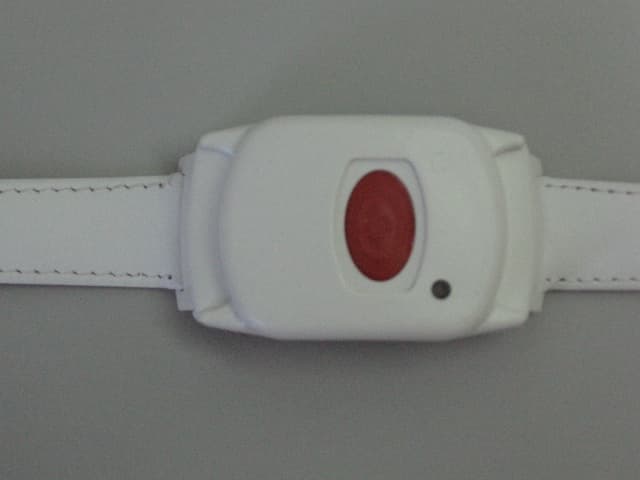
GSAWPK250
Jun 03, 2007PANIC WATCH
Equipment Class
DSC - Part 15 Security/Remote Control Transmitter
GSA5-RLE00125B
May 28, 2007LF Exciter
Equipment Class
DCD - Part 15 Low Power Transmitter Below 1705 kHz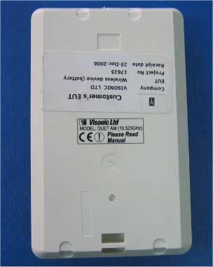
GSADUETAM
May 16, 2007Dual-Technology Microwave/PIR Intrusion Detector
Equipment Class
FDS - Part 15 Field Disturbance Sensor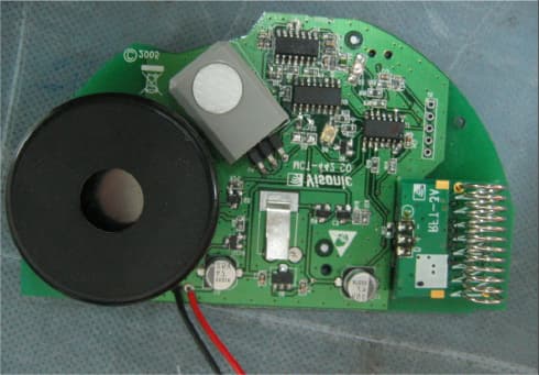
GSAMCT442
May 01, 2007Supervised Indoor Wireless CO Gas Detector
Equipment Class
DSC - Part 15 Security/Remote Control Transmitter