GSAMDT122Personal Security Transmitter
Visonic Inc.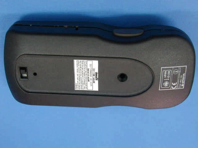
Click to zoom
Application Details
- Equipment Class
- DSC - Part 15 Security/Remote Control Transmitter
- Date of Grant
- Jul 01, 2003
- Application Purpose
- Original Equipment
- Date of Application
- Jul 01, 2003
- Equipment Note
- Personal Security Transmitter
- Frequency Range
- 433.92000000 - 433.92000000
- Company
- Visonic Inc.
- Country
- United States
Documents & Files
Document Text
Text extracted from the exhibit documents filed with the FCC. Open a document above to read the original.
Users Manual
DE2295U 1 MDT MDTMDT MDT- -- -122 122 122 122 Man-Down Transmitter Response User’s Guide 1. INTRODUCTION 1. INTRODUCTION1. INTRODUCTION 1. INTRODUCTION MDT-122 is an automatic personal security transmitter. This micro-processor controlled transmitter is designed for use by guards in a prison, by security officers in an organization or institution, or by employees in a large industrial complex (as an industrial signaling device for safety). In areas that 1 person is not allowed to work alone, MDT-122 can be an excellent solution. The MDT-122 alarm signal can be received by a compatible receiver, like MCR-308, and can be integrated in any alarm system. MDT-122 is attached to the guard’s pouch / holster. The transmitter is activated in the following events (see fig. 2): A. PANIC When the guard needs help, he presses both buttons (pressing both buttons is required to prevent an accidental panic message transmission). B. MANDOWN When the guard falls down (automatic transmission when the unit is tilted down by more than 60 ° ). C. PULL-CORD The pull-cord is attached strongly by a clip to the guard’s belt on one side and is plugged into the transmitter by an easily detachable plastic pin on the other side. Pulling the cord or the unit away causes the plastic pin to be detached and to release an internal switch that activates an alarm transmission. This may happen when an attacker tries to draw the unit away from the guard or by the holder, in case of emergency and difficulty to press the twin buttons for alarm. Figure 2 - External View Figure 3 - Activating the Internal Tilt Switch MDT-122 2 MCR-308 wireless receiver 1 Public telephone exchange OUT L. BAT JAMM READY BYPASS POWER ARM HOME AWAY ND 1 4 7 CLR 2 5 8 0 3 6 9 ENT A B C D 2 Optional alarm system Optional automatic dialer AU TOM ATI C 2 - CHANNEL SPEECH DIALER DIAL Model: DL- BCD EF A-FA PROG STOP AL-1 AL-2 PROGRAM ALARM-1 ALARM-2 STOP 3 456 789 * 0# 1 2 3 Siren Figure 1 - Integration of MDT-122 in an Alarm System Vertical (normal) Position Left pushbutton Tilt ON/OFF slide switch Pull cord Cover screw Right push button LED Temporary TILT OFF push-button 2 DE2295U 2. SPECIFICATIONS 2. SPECIFICATIONS2. SPECIFICATIONS 2. SPECIFICATIONS Transmission Type: Radio Frequency (RF) RF frequency (MHz): 433.92 Transmitter’s ID Code: 28-bit ID, Code Secure TM Modulation type: pulse width modulation Overall Message Length: 66 bit Alarm Messages : Tilt activated, pull-cord disconnected, Panic alarm, each with separate ID Power Source: 3.6 V, Lithium battery, size 1/2 AA / 1.2 Ah, (Tadiran TL-2150 or equivalent.) Current Consumption: 15 μ A standby, 10mA (operation) Battery Life Expectancy: Up to 3 years (with regular use) Battery Supervision: Battery test every hour Operating temperature: 0 ° C to 49 ° C (32 ° F to 120 ° F) Dimensions (H x W x D) : 120 x 52 x 36 mm (4-3/4 x 2-1/16 x 1-5/16 in.) With Holster - 3 : 140 x 77 x 50 mm (5-7/16 x 3-1/16 x 1-15/16 in.) Housing: 3mm ABS plastic box, weather proof Weight: Man-down -138 g (4.9 Oz.), Holster-3 - 30 g (1.05 Oz.) Color: Body - dark gray, buttons - brown, pull cord - black Compliance with Std.: FCC Part 15 Accessories: Light weight water-resistant carry pouch Holster-3. Metal belt clip. Pull-cord with pin and cloth clip. 3. FUNCTIONAL DESCRIPTION 3. FUNCTIONAL DESCRIPTION3. FUNCTIONAL DESCRIPTION 3. FUNCTIONAL DESCRIPTION 3.1 Visual and Audible Warning Timing A built-in tilt sensor activates the unit when the unit is tilted down by more than 60 ° (see figure 3). When the unit is activated, it enters a pre-alarm state for 30 seconds. This period enables the user to return the transmitter to the normal (vertical) position, to prevent an unintentional alarm transmission. During this period an audible warning is sounded by the buzzer and a visual warning is indicated (by the internal LED). The buzzer’s sound can be disabled by using an internal buzzer’s switch (see table 1). Figure 4 presents the timing diagram. Prealarm time: 15 short beeps + 1 long beep Buzzer sound 030 t (sec.) MDT-122 is returned to normal position before 30 sec. 030 MDT-122 is returned to normal position after 30 sec. ON OFF Part of prealarm time Transmission and LED 030 t (sec.) Alarm Alarm restore ON OFF Figure 4 - MDT-122 Functional Timing Diagram 3.2 Low Battery Voltage Indication The battery is automatically tested every hour, under load condition. If the battery voltage is low, “low battery” message is sent every transmission. In addition, when the battery voltage is low, the LED blinks while pressing the left or right push-button switch. 3.3 External Buttons Functions (see fig. 2) A. Left or Right push-buttons When left and right push-buttons are pressed, panic alarm is transmitted. B. Tilt ON-OFF Slide Switch By using this switch, the user can disable the tilt sensor function (this is necessary when a guard goes off duty or performs such activities that can activate the transmitter and create a false alarm). When the unit is delivered from the factory, the switch is in OFF position. C. Temp Tilt Off Push-Button Switch The push-button is located at the top of the unit. It is used for temporary disabling (5 minutes) of the tilt sensor function, when it is desired. To re-enable tilt function before the 5 minutes delay expires, the tilt ON-OFF slide switch should be switched to OFF position and then to ON again. 3.4 Pull-Cord Function (see par. 1C) 3.5 Internal DIP Switches Functions Table 1 - Internal DIP Switches Functions Switch Description Default 1 Buzzer ON/OFF ON 2 Pull-cord option ON 3 (not used) OFF 4 (not used) OFF 5 (For future use) - 6 Tilt alarm delay ON/OFF (*) ON * Tilt Alarm Delay Enable/Disable 30 second pre-alarm delay enabled/disabled. If the “tilt alarm delay” DIP switch is set to OFF position (no delay) the tilt pre-alarm DIP switch position is disregarded. 3.6 Buzzer Functions The internal buzzer sounds, as shown in figure 4 and in the following situations: A. When someone is tampering / stops tampering w…
Text truncated - open the document above for the full version.
Block Diagram
123450 CONFIDENTIAL This document contains information whichis proprietary to Visonic Ltd., Israel. Theuse, copy or dissemination of this materialfor any purpose other than that for which itis intended is prohibited with out the priorwritten consent of Visonic Ltd.Date Released: To Whom: Apx 2-1-3Designed:Drew:Updated:Approved: Name Date Product Name:Drawing Name: Signature Sheet No./of: Scale:Catalog No.:Drawing No.:File Name: Doc. Rev.: Upd ECOs MDT-122 (433) RESPONSELINK Block Diagram KOBI F.MARIA K. 28.05.03 1/1 0-2295-50F-2295-500F229550.VSD 0 Microcontroller PIC16LC73A EEPROM 24LC02B Microcontroler PIC16LC505 Transmiter 433M H z Encoder HCS300 Buzzer Led Battery 3.6V 4MHz Crystal Oscillator P U SHBUTTON 1 Tamper PUSHBUTTON 2 DIP SWITCH 1 TO 6 PULL CORD ENABLE/DISABLE TILT ON/ OFF TILT DISABLE 5 MIN TILT SWITCH 28.05.0328.05.03 PINHAS I.
Cover Letter(s)
July 2, 2003 American TCB 6731 Whittier Ave Suite C110 McLean, VA 22101 USA Subject: Request for confidentiality for personal security transmitter, model: MDT-122, FCC ID: GSAMDT122 Dear Gentlemen, We apply to you with request to withhold Visonic Ltd. trade secrets in Application for Certification for FCC ID: GSAMDT122. These trade secrets can be found in the transmitter schematic diagrams (2 pages of this Application) and in the transmission description (1 page of this Application). Many thanks in advance. Yaacov Kotlicki Directing Manager Head Office 30 Habarzel Street Tel Aviv 69710 Israel Postal Address P.O.B. 22020 Tel Aviv 61220 Israel Tel 972 3 6456789 Fax 972 3 6456788
Cover Letter(s)
July 2, 2003 American TCB 6731 Whittier Ave Suite C110 McLean, VA 22101 USA Subject: Application for certification of personal security transmitter, model: MDT-122, FCC ID:GSAMDT122 Dear Gentlemen, Please find attached our application for certification of personal security transmitter, FCC ID:GSAMDT122, prepared in accordance with FCC Rules, parts 15 and 2. The product testing and this application for certification were performed by Hermon Laboratories, which is listed by FCC. Hermon Labs responsible person is Mr. Gonen Usishkin, tel: 011 972 4628 8001, fax:011 972 4628 8277, e-mail: [email protected] . Please send an invoice to Hermon Labs. We hope this application satisfies your requirements Yaacov Kotlicki Directing Manager Head Office 30 Habarzel Street Tel Aviv 69710 Israel Postal Address P.O.B. 22020 Tel Aviv 61220 Israel Tel 972 3 6456789 Fax 972 3 6456788
External Photos
Page 1 of 3 MDT-122 EXTERNAL PHOTOGRAPHS This document contains 2 photographs Page 2 of 3 Photograph No.1 MDT-122 front view Page 3 of 3 Photograph No.2 MDT-122 rear view
Internal Photos
Page 1 of 7 MDT-122 INTERNAL PHOTOGRAPHS This document contains 6 photographs Page 2 of 7 Photograph No.1 Internal view Page 3 of 7 Photograph No.2 PCB first side with RFT-3A module Page 4 of 7 Photograph No.3 PCB first side without RFT-3A module Page 5 of 7 Photograph No.4 PCB second side Page 6 of 7 Photograph No.5 RFT-3A module component side Page 7 of 7 Photograph No.6 RFT-3A module printed side
Operational Description
MDT-122 Man-Down Transmitter 1. Description MDT-122 is an automatic personal security transmitter. This micro-processor controlled transmitter is designed for use by guards in a prison, by security officers in an organization or institution, or by employees in a large industrial complex (as an industrial signaling device for safety). In areas that 1 person is not allowed to work alone, MDT-122 can be an excellent solution. The MDT-122 alarm signal can be received by a compatible receiver, like MCR-308, and can be integrated in any alarm system. MDT-122 is attached to the guard’s pouch / holster. The transmitter is activated in the following events (see fig. 2): A. PANIC When the guard needs help, he presses both buttons (pressing both buttons is required to prevent an accidental panic message transmission). B. MANDOWN When the guard falls down (automatic transmission when the unit is tilted down by more than 60°). C. PULL-CORD The pull-cord is attached strongly by a clip to the guard’s belt on one side and is plugged into the transmitter by an easily detachable plastic pin on the other side. Pulling the cord or the unit away causes the plastic pin to be detached and to release an internal switch that activates an alarm transmission. This may happen when an attacker tries to draw the unit away from the guard or by the holder, in case of emergency and difficulty to press the twin buttons for alarm. MDT-122 2 MCR-308 wireless receiver 1 Public telephone exchange OUT L. BAT JAMM READY BY PASS PO WER ARM HOME AWAY ND 1 4 7 CLR 2 5 8 0 3 6 9 ENT A B C D 2 Optional alarm system Optional automatic dialer AU TO M ATI C 2 - CHANNEL SPEECH DIALER DIAL Mo d e l : D L - BCD EF A-FA PROG STOP AL-1 AL-2 PROGRAM ALARM -1 ALARM -2 STOP 3 4 56 789 * 0# 1 2 3 Siren Figure 2 - External View Figure 3 - Activating the Internal Tilt Switch Vertical (normal) Position Left pushbutton Tilt ON/OFF slide switch Pull cord Cover screw Right push button LED Temporary TILT OFF push-button 2. Specifications Transmission type: Radio Frequency (RF) RF frequency (MHz): 433.92 Transmitter’s ID code: 28-bit ID, Code Secure TM Modulation type: pulse width modulation Overall message length: 66 bit Alarm messages: Tilt activated, pull-cord disconnected, Panic alarm, each with separate ID Power source: 3.6 V, Lithium battery, size 1/2 AA / 1.2 Ah, (Tadiran TL-2150 or equivalent.) Current consumption: 15μA standby, 10mA (operation) Battery life expectancy: Up to 3 years (with regular use) Battery supervision: Battery test every hour Operating temperature: 0°C to 49°C (32°F to 120°F) Dimensions (H x W x D): 120 x 52 x 36 mm (4-3/4 x 2-1/16 x 1-5/16 in.) With Holster-3: 140 x 77 x 50 mm (5-7/16 x 3-1/16 x 1-15/16 in.) Housing: 3mm ABS plastic box, weather proof Weight: Man-down -138 g (4.9 Oz.), Holster-3 - 30 g (1.05 Oz.) Color: Body - dark gray, buttons - brown, pull cord - black Compliance with Std.: FCC Part 15 Accessories: Light weight water-resistant carry pouch Holster-3. Metal belt clip. Pull-cord with pin and cloth clip. 3. Internal antenna description A piece of wire AWG 24, 15 cm long inside the casing is used as an antenna.
Test Report
This report is in conformity with ISO/IEC 17025. The A2LA logo endorsement applies only to the test methods and the standards that are listed in the scope of Hermon Laboratories accreditation. The test results relate only to the items tested. This test report must not be reproduced in any form except in full with the approval of Hermon Laboratories Ltd. Page 1 of 45 Document ID: VISRAD_FCC.15421.doc Date of Issue: May 2003 HERMON LABORATORIES Electrical Hermon Laboratories Ltd. P.O.Box 23 Binyamina 30500, Israel Tel.+972 66288001 Fax.+972 66288277 e-mail: [email protected] Approved by: _________________ Mr. Arick Elshtein, International Standards Department Manager Visonic Ltd. RADIO TEST REPORT ACCORDING TO 47 CFR Part 15 SUBPART C §15.231, §15.205, §15.209 and SUBPART B for VISONIC Ltd. EQUIPMENT UNDER TEST: Personal security transmitter Model: MDT-122 (433.92) Page 2 of 45 Document ID: VISRAD_FCC.15421.doc Date of Issue: May 2003 HERMON LABORATORIES Hermon Laboratories Ltd. P.O.Box 23 Binyamina 30500, Israel Tel.+972 66288001 Fax.+972 66288277 e-mail: [email protected] Contents CONTENTS......................................................................................................................................................................................................2 1 PROJECT INFORMATION......................................................................................................................................................................3 2 SUMMARY OF TESTS AND REQUIREMENTS.....................................................................................................................................4 3 EUT DESCRIPTION................................................................................................................................................................................6 3.1 GENERAL DESCRIPTION..................................................................................................................................................................6 3.2 EUT TEST CONFIGURATION...........................................................................................................................................................6 3.3 TRANSMITTER DESCRIPTION...........................................................................................................................................................7 4 TEST RESULTS......................................................................................................................................................................................8 4.1 BANDWIDTH OF EMISSION ACCORDING TO § 15.231 (C)...............................................................................................................8 4.2 FIELD STRENGTH OF FUNDAMENTAL, § 15.231.............................................................................................................................9 4.3 FIELD STRENGTH OF SPURIOUS RADIATION, § 15.231, § 15.205..............................................................................................10 4.4 UNINTENTIONAL RADIATED EMISSIONS TEST, §15.109...............................................................................................................14 APPENDIX A PLOTS.................................................................................................................................................................................15 APPENDIX B TEST SETUP PHOTOGRAPHS..........................................................................................................................................27 APPENDIX C TEST EQUIPMENT USED FOR TESTS..............................................................................................................................33 APPENDIX D TEST EQUIPMENT CORRECTION FACTORS..................................................................................................................34 APPENDIX E GENERAL INFORMATION..................................................................................................................................................44 TEST FACILITY DESCRIPTION......................................................................................................................................................................44 ABBREVIATIONS AND ACRONYMS...............................................................................................................................................................44 SPECIFICATION REFERENCES....................................................................................................................................................................44 FCC EQUIPMENT CODES AND DESCRIPTIONS...........................................................................................................................................45 Page 3 of 45 Document ID: VISRAD_FCC.15421.doc Date of Issue: May 2003 HERMON LABORATORIES Hermon Laboratories Ltd. P.O.Box 23 Binyamina 30500, Israel Tel.+972 66288001 Fax.+972 66288277 e-mail: [email protected] 1 Project information Description of equipment under test Test item : Personal security transmitter Manufacturer : Visonic Ltd. Type (Model) : MDT-122 (433.92) Equipment FCC code 1 : DSC Applicant information Applicant’s responsible person : Mr. Arick Elshtein, International Standards Department Manager Company : Visonic Ltd. Address : 27, Habarzel street City : Tel Aviv Postal code : 69710 Country : Israel Telephone number : +972 3645 6714 Telefax number : +972 3645 6891 Test performance Project number: : 15421 Location : Hermon Laboratories Receipt date : January 23, 2003 Test performed : March 20, 2003 Purpose of test : Apparatus compliance verification in accordance with emission requirements Test specifications : 47CFR Part 15, subpart C, §15.231, §15.205, §15.209, and subpart B §15.109 1 FCC Equipment codes – see Appendix E Page 4 of 45 Document ID: VISRAD_FCC.15421…
Text truncated - open the document above for the full version.
Test Setup Photos
Photograph 1 Spurious emission measurements test setup view with loop antenna, performed in anechoic chamber in 9 kHz – 30 MHz range Photograph 2 20 dB bandwidth, field strength of fundamental, harmonics emission measurements test setup view with log periodic antenna, performed at OATS in 200 – 1000 MHz range Photograph 3 Spurious emission measurements test setup view with double ridged guide antenna, performed in anechoic chamber in 1 – 5 GHz range Photograph 4 Unintentional radiated emission measurements test setup view with biconical antenna, performed in anechoic chamber in 30 – 200 MHz range Photograph 5 Unintentional radiated emission measurements test setup view with log periodic antenna, performed in anechoic chamber in 200 – 1000 MHz range Photograph 6 EUT view
Contact Information
Applicant
Scott Jensen(Tec Manager)
860-243-0833
Technical Contact
Hermon LaboratoriesGonen Usishkin
[email protected]972 4 628 8001
Harakevet Industrial zone · Binyamina · Israel
Test Firm
Hermon Laboratories Ltd.Alexander Usoskin
Technical Specifications
| # | Rule Parts | Frequency Range | Power Output |
|---|---|---|---|
| 1 | 15.231 | 433.92 MHz - 433.92 MHz | - |
Other Applications from Visonic Inc.

GSA5-BTC00433
Nov 14, 2007Infant Protection Bracelet
Equipment Class
DSC - Part 15 Security/Remote Control Transmitter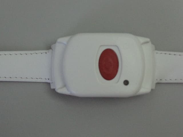
GSAWPK250
Jun 03, 2007PANIC WATCH
Equipment Class
DSC - Part 15 Security/Remote Control Transmitter
GSA5-RLE00125B
May 28, 2007LF Exciter
Equipment Class
DCD - Part 15 Low Power Transmitter Below 1705 kHz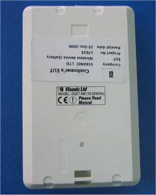
GSADUETAM
May 16, 2007Dual-Technology Microwave/PIR Intrusion Detector
Equipment Class
FDS - Part 15 Field Disturbance Sensor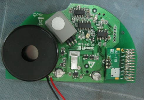
GSAMCT442
May 01, 2007Supervised Indoor Wireless CO Gas Detector
Equipment Class
DSC - Part 15 Security/Remote Control Transmitter