GSAMDT122S
Visonic Inc.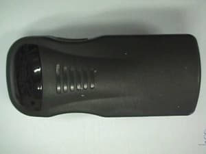
Click to zoom
Application Details
- Equipment Class
- DSC - Part 15 Security/Remote Control Transmitter
- Date of Grant
- Jul 07, 1999
- Application Purpose
- Original Equipment
- Date of Application
- Jun 01, 1999
- Frequency Range
- 315.00000000 - 315.00000000
- Company
- Visonic Inc.
- Country
- United States
Documents & Files
Document Text
Text extracted from the exhibit documents filed with the FCC. Open a document above to read the original.
Users Manual
DE2291Ufirst MDT-122 S MDT-122 SMDT-122 S MDT-122 S RF / IR Man-Down Transmitter User’s Guide 1. INTRODUCTION 1. INTRODUCTION1. INTRODUCTION 1. INTRODUCTION The MDT-122 S is an automatic personal security transmitter. This micro-processor controlled transmitter is designed for use by guards in a prison, by security officers in an organization or institution, or by employees in a large industrial complex (as an industrial safety device). The unit is a part of the SpiderAlert network. The transmitter is activated in the following events: 1. PANIC When the guard needs help, he presses both buttons (pushing both buttons is required to prevent an accidental panic message transmission). 2. MANDOWN When the guard falls down (automatic transmission when the unit is tilted by more than 60 ° ). 3. PULL-CORD The MDT-122 S automatically transmits a pull-cord alarm: A.When the unit is forcibly pulled from the holder and the pull cord is detached from the holder’s belt B.When the unit is intentionally pulled by the holder (emergency event) and the pull cord is detached from his belt. 4. TAMPER When the transmitter is opened by an unauthorized person. 5. LEFT OR RIGHT BUTTON When the guard presses the left or right push-button, an attendance message is sent to the security main station (confirming that he is not attacked) and the unit is also tested (the LED is lit). When activated, the transmitter delivers an identifiable alert message (one of various messages, according to the events predetermined priority) to the main security station. Figure 1 - External View Figure 2 - Activating the Internal Tilt Switch When the transmitter is activated, the holder’s name and exact location are displayed on main security station screen (according to the SpiderAlert network programming) and a siren and/or audible alarm are activated, to provide the necessary help (see figure 3). The transmitter is attached to the user’s belt with a clip like a pager, or inside a pouch / holster and connected with a pull cord to the guard’s belt. The transmitter is not activated during the guard’s regular daily activities (running, jumping, sitting, bending, removing cloths, going to bathroom and going off and on duty). 4. USING THE MDT-122 S 4. USING THE MDT-122 S4. USING THE MDT-122 S 4. USING THE MDT-122 S 4.1 Initial Functions When the MDT-122 S leaves the factory, the internal battery contact (+) is covered by an isolation foil. To make the unit operational, perform the following actions: 1st. Press the belt clip, by your hand, to gain access to the MDT- 122 S cover’s screw (see figure 1). 2nd. Remove the cover Philips screw. 3rd. Press (with your finger) at the center of the top side (on the TEMP TILT OFF inscription) and carefully open the front cover. Caution: When opening the MDT-122 S, the IR LEDs should not be touched, to prevent their movement. If the IR LEDs are moved, the IR beams may not be directed towards the IR window and as a result the IR transmission range might be reduced. Vertical (normal) Position 60 ° tilt 60 ° tilt Left pushbutton Temporary TILT OFF push-button Tilt ON/OFF slide switch Belt clip Pull cord Cover’s screw (between belt clip’s jaws) Right pushbutton LED IR window SpiderAlert main station SpiderBus MDT-122 S in alarm (transmission) position SR-520 RF+IR receiver Attacked holder’s name and location are displayed on the screen SpiderAlert network controller I/O unit with Siren / loudspeaker ❇ John Markus is attacked! Paging transmitter Guards with pagers Figure 3 - MDT-122 S Integration in the SpiderAlert Network D2291Usecond 4th. Pull out the isolation foil that is inserted between the battery to the battery holder (+) pole. 5th. Change DIP switches positions as desired (see table 1). 6th. Put the unit’s cover on its place. 7th. Press the belt clip, by your hand, to gain access to the cover’s screw hole. 8th. Insert the cover screw and secure it with a Philips screw- driver. 4.2 Individual or Shift Rotated Units The MDT-122 S can be used as: A. Individual Transmitter When the MDT-122 S is used as a personal transmitter for each guard: One. There is only one responsible guard for the transmitter and therefore it is better handled. Two. It is not necessary to update the holder name every shift. Three. There is no need for check-in and check-out for the transmitter turn over. B. Shift-rotated transmitter When the MDT-122 S is turned over among holders in different shifts: One. There is saving on units quantities. Two. The turn-over action should be controlled by a dedicated person Three. It is necessary to update the guard’s name on the software, whenever the unit is turned over to another guard 4.3 Using the Pull Cord Alarm Option If it is desired to disable the pull cord option, it is necessary to move the internal DIP switch number 2 to OFF position, as described in section 3.5 (default position is ON). 4.4 Selecting Other Desired Options Select the buzzer ON/OFF, supervision ON/OFF, supervision message type, pre-tilt alarm and tilt alarm delay ON/OFF options, as detailed in section 3.5. 5. MAINTENANCE 5. MAINTENANCE5. MAINTENANCE 5. MAINTENANCE No maintenance is required for the MCT-122 S, except replacement of the internal battery. The battery is automatically tested every 1 hour. If the battery voltage is low, a “low battery” warning message is automatically included in every transmission and the unit’s LED indicator flashes (while pressing the left or right push-button switch) until the battery is replaced. Replace the 3.6 V Lithium battery, as follows (see fig. 6): 1st. Open the unit’s cover, as described in paragraph 4.1A - 4.1C. 2nd. Remove the old battery and install a new one. Verify that the battery poles (+) and (-) are located as marked on the battery housing. 3rd. Close the unit’s cover, as described in paragraph 4.1F - 4.1H. 4th. Use moderate pressure to close the cover, with your fingers, until its snaps shut. 5th. Secure the front cover with its screw. Figure 6 - Isometric vi…
Text truncated - open the document above for the full version.
Block Diagram
FCC ID:GSAMDT122S Date: May, 1999 Project number:13331Page 1 of 3 BLOCK DIAGRAM FCC ID:GSAMDT122S Date: May, 1999 Project number:13331Page 2 of 3
Cover Letter(s)
Visonic Ltd June 1, 1999 FEDERAL COMMUNICATIONS COMMISSION EQUIPMENT APPROVAL SERVICES P.O.B. 358315 Pittsburgh, PA 15251-5315 USA Subject: Application for certification of MDT-122S security transmitter, FCC ID:GSAMDT122S Dear Gentlemen, Please find attached our application for certification of MDT-122S security transmitter, FCC ID:GSAMDT122S, prepared in accordance with FCC Rules, parts 2 and 15. The product testing and this application for certification were performed by Hermon Laboratories, which is listed by FCC. Hermon Labs responsible person is Dr. Edward Usoskin, tel: 01197266288001, fax:01197266288277, e-mail: [email protected]. We hope this application satisfies your requirements. Sincerely yours, Arick Elshtein, technical support manager Visonic Ltd. Head Office 30 Habarzel Street Tel Aviv 69710 Israel Postal Address P.O.B. 22020 Tel Aviv 61220 Israel Tel 972 3 6456789 Fax 972 3 6456788
External Photos
FCC ID:GSAMDT122S Date: May, 1999 Project number:13331Page 1 of 3 EXTERNAL PHOTOGRAPHS This document contains 2 photographs FCC ID:GSAMDT122S Date: May, 1999 Project number:13331Page 2 of 3 Photograph No.1 MDT-122S transmitter general view FCC ID:GSAMDT122S Date: May, 1999 Project number:13331Page 3 of 3 Photograph No.2 MDT-122S transmitter back side view
ID Label/Location Info
FCC ID:GSAMDT122S Date: May, 1999 Project number:13331 Page 1 of 1 LABEL The label shown below is affixed on the rear panel of MDT-122S transmitter
Internal Photos
FCC ID:GSAMDT122S Date: May, 1999 Project number:13331Page 1 of 4 INTERNAL PHOTOGRAPHS This document contains 3 photographs FCC ID:GSAMDT122S Date: May, 1999 Project number:13331Page 2 of 4 Photograph No.1 MDT-122S transmitter internal view FCC ID:GSAMDT122S Date: May, 1999 Project number:13331Page 3 of 4 Photograph No.2 MDT-122S transmitter PCB view FCC ID:GSAMDT122S Date: May, 1999 Project number:13331Page 4 of 4 Photograph No.3 MDT-122S transmitter PCB back side view
Operational Description
DE2291Ufirst MDT-122 S MDT-122 SMDT-122 S MDT-122 S RF / IR Man-Down Transmitter User’s Guide 1. INTRODUCTION 1. INTRODUCTION1. INTRODUCTION 1. INTRODUCTION The MDT-122 S is an automatic personal security transmitter. This micro-processor controlled transmitter is designed for use by guards in a prison, by security officers in an organization or institution, or by employees in a large industrial complex (as an industrial safety device). The unit is a part of the SpiderAlert network. The transmitter is activated in the following events: 1. PANIC When the guard needs help, he presses both buttons (pushing both buttons is required to prevent an accidental panic message transmission). 2. MANDOWN When the guard falls down (automatic transmission when the unit is tilted by more than 60 ° ). 3. PULL-CORD The MDT-122 S automatically transmits a pull-cord alarm: A.When the unit is forcibly pulled from the holder and the pull cord is detached from the holder’s belt B.When the unit is intentionally pulled by the holder (emergency event) and the pull cord is detached from his belt. 4. TAMPER When the transmitter is opened by an unauthorized person. 5. LEFT OR RIGHT BUTTON When the guard presses the left or right push-button, an attendance message is sent to the security main station (confirming that he is not attacked) and the unit is also tested (the LED is lit). When activated, the transmitter delivers an identifiable alert message (one of various messages, according to the events predetermined priority) to the main security station. Figure 1 - External View Figure 2 - Activating the Internal Tilt Switch When the transmitter is activated, the holder’s name and exact location are displayed on main security station screen (according to the SpiderAlert network programming) and a siren and/or audible alarm are activated, to provide the necessary help (see figure 3). The transmitter is attached to the user’s belt with a clip like a pager, or inside a pouch / holster and connected with a pull cord to the guard’s belt. The transmitter is not activated during the guard’s regular daily activities (running, jumping, sitting, bending, removing cloths, going to bathroom and going off and on duty). 2. SPECIFICATIONS 2. SPECIFICATIONS2. SPECIFICATIONS 2. SPECIFICATIONS Vertical (normal) Position 60 ° tilt 60 ° tilt Left pushbutton Temporary TILT OFF push-button Tilt ON/OFF slide switch Belt clip Pull cord Cover’s screw (between belt clip’s jaws) Right pushbutton LED IR window SpiderAlert main station SpiderBus MDT-122 S in alarm (transmission) position SR-520 RF+IR receiver Attacked holder’s name and location are displayed on the screen SpiderAlert network controller I/O unit with Siren / loudspeaker ❇ John Markus is attacked! Paging transmitter Guards with pagers Figure 3 - MDT-122 S Integration in the SpiderAlert Network 2DE2291U Transmission types: Infra-Red (IR) and Radio Frequency (RF). RF frequency (MHz): 315, 404, 418 or 433.92. Transmitter’s ID code: 24-bit digital word, pulse width modulation. Overall message length: 36 bit Power source: 3.6 V, Lithium battery, size 1/2 AA / 1.2 Ah, (Tadiran TL-2150 or equivalent.) Current consumption: 15 μ A standby, 10 mA in operation (including LED). Battery life: 3-4 years in normal use Battery supervision: battery condition data is automatically included in every transmitted message. Operating temperature: 0 ° C to 49 ° C (32 ° F to 120 ° F) Dimensions (H x W x D) : 123 x 54 x 50 mm (4-13/16 x 2-1/8 x 1-15/16 in.) including belt clip. Housing: 3mm ABS plastic box Weight: 138 g (4.9 Oz.) Color: Dark gray D2291U 3 3. FUNCTIONAL DESCRIPTION 3. FUNCTIONAL DESCRIPTION3. FUNCTIONAL DESCRIPTION 3. FUNCTIONAL DESCRIPTION 3.1 Visual and Audible Warning Timing A built-in tilt sensor activates the unit when the unit is tilted by more than 60 ° (see figure 2). When the unit is activated, it enters to a pre-alarm state for 15 seconds. This period enables the user to return the transmitter to the normal (vertical) position, to prevent an unintentional false alarm transmission. During this period an audible warning is sounded by the buzzer and a visual warning is indicated by the internal LED). The buzzer’s sound can be disabled by using an internal buzzer’s switch. The unit’s functional timing is presented in figure 4. Figure 4 - MDT-122 S Functional Timing Diagram * t 0 = MDT-122 S activation time . ** Pre-alarm state starts with a pre-alarm transmission. If the transmitter is returned to normal (vertical) position within 15 seconds, pre-alarm cancellation signal (restore message) is transmitted to the main security station. When the internal tilt pre- alarm DIP switch is set to OFF position, the pre-alarm and cancellation transmissions are not enabled. *** Alarm state starts 15 seconds after the unit activation, every 30 seconds, for 5 minutes. If during this period the unit is returned to normal (vertical) position, the transmitter transmits alarm restore message (only after 5 minutes) to the main security station. 3.2 Detailed Transmission Description Once triggered, the transmitter sends out an RF and IR signals with a 24-bit identification code. This code identifies the Man- Down transmitter to the main station that automatically displays the holder’s name and exact location on the central computer’s screen (figure 3). A supervision message (an option applicable with the proper software version) is automatically transmitted by the unit. It is transmitted every 30 seconds (in emergency situation) or 60 minutes (in non-emergency situation), according to position of an internal “supervision type” DIP switch. The main security station is thus informed, at regular intervals, about the MDT-122 S active participation in the system. Benefit of utilizing Dual (RF+IR) technology The main benefit of using the dual (RF+IR) technology is the capacity to pinpoint the user (transmitter) location in multi-store buildings. The RF transmission, including 24-bit user ID, penetrates wall…
Text truncated - open the document above for the full version.
Schematics
FCC ID:GSAMDT122S Date: May, 1999 Project number:13331Page 1 of 2 SCHEMATIC DIAGRAM FCC ID:GSAMDT122S Date: May, 1999 Project number:13331Page 2 of 2
Test Report
Test Report:VISFCC.13331 Date: May, 1999 Total: 24 pages FCC ID: GSAMDT122S Page 1 of 24 HERMON LABORATORIES ELECTROMAGNETIC EMISSIONS TEST REPORT ACCORDING TO FCC PART 15, SUBPART C, §15.231 FOR VISONIC Ltd. EQUIPMENT UNDER TEST PERSONAL SECURITY TRANSMITTER, MDT-122S Prepared by: _________________ Mrs. M. Cherniavsky, certif. engineer Hermon Labs Approved by: _________________ Mr. A. Usoskin, QA manager Hermon Labs Approved by: _________________ Dr. E. Usoskin, C.E.O. Hermon Labs Approved by: _________________ Mr. Arick Elshtein, technical support manager Visonic Ltd. Hermon Laboratories Ltd. P.O.Box 23 Binyamina 30550, Israel Tel.+972-6628-8001 Fax.+972-6628-8277 Email:[email protected] Test Report:VISFCC.13331 Date: May, 1999 FCC ID: GSAMDT122S Page 2 of 24 HERMON LABORATORIES Description of equipment under test Test itemsSecurity transmitter, FCC ID:GSAMDT122S ManufacturerVisonic Ltd. Trade MarkNA Type (Model)MDT-122S Applicant information Applicant’s representative & responsible personMr. Arick Elshtein, technical support manager CompanyVisonic Ltd. Address30 Habarzel St. P.O. Box22020 Postal code61220 CityTel Aviv CountryIsrael Telephone number011-972-3645 6714 Telefax number 011-972-3645 6789 Test performance Project Number13331 Location of the testHermon Laboratories, Binyamina, Israel Test startedMarch 15, 1999 Test completedMarch 15, 1999 Purpose of testThe EUT certification in accordance with CFR 47, part 2, §2.1033 Test specification(s)FCC part 15 subpart C §15.231, §15.209 subpart B, §15.109 The A2LA logo endorsement applies only to the test methods and the standards that are listed in the scope of Hermon Laboratories accreditation by A2LA. Through this report period is used as decimal separator while thousands are separated by comma. This report is in conformity with EN 45001 and ISO GUIDE 25. The test results relate only to the items tested. This test report must not be reproduced in any form except in full, with the approval of Hermon Labs Ltd. Test Report:VISFCC.13331 Date: May, 1999 FCC ID: GSAMDT122S Page 3 of 24 HERMON LABORATORIES Table of Contents 1GENERAL INFORMATION..........................................................................................................4 1.1ABBREVIATIONS AND ACRONYMS.................................................................................................4 1.2SPECIFICATION REFERENCES........................................................................................................5 1.3EUT DESCRIPTION......................................................................................................................5 1.4STATEMENT OF MANUFACTURER..................................................................................................6 2TEST FACILITY DESCRIPTION.................................................................................................7 2.1GENERAL....................................................................................................................................7 2.2EQUIPMENT CALIBRATION...........................................................................................................7 2.2.1Expanded uncertainty at 95% confidence in Hermon Labs EMC measurements.................7 2.3LABORATORY PERSONNEL...........................................................................................................8 2.4STATEMENT OF QUALIFICATION...................................................................................................8 3RADIATED EMISSION MEASUREMENTS................................................................................9 3.1FIELD STRENGTH OF EMISSIONS ACCORDING TO § 15.231 (B)..............................................................9 3.1.1Specified limits at 3 m distance..........................................................................................9 3.1.2Test procedure and results..................................................................................................9 3.2BANDWIDTH OF EMISSION ACCORDING TO § 15.231 (C)...............................................................15 3.2.1Specified limits.................................................................................................................15 3.2.2Test procedure and results................................................................................................15 3.3PERIODIC OPERATION REQUIREMENT §15.231(A)(1)....................................................................17 3.4UNINTENTIONAL RADIATED EMISSIONS TEST ACCORDING TO §15.109, §15.209............................18 3.4.1Definition of the test.........................................................................................................18 3.4.2The test set-up configuration............................................................................................18 4SUMMARY AND SIGNATURES.................................................................................................18 APPENDIX A - TEST EQUIPMENT AND ANCILLARIES USED FOR TESTS.............................18 APPENDIX B-TEST EQUIPMENT CORRECTION FACTORS......................................................18 Test Report:VISFCC.13331 Date: May, 1999 FCC ID: GSAMDT122S Page 4 of 24 HERMON LABORATORIES 1General information 1.1Abbreviations and acronyms The following abbreviations and acronyms are applicable to this test report: AVRGaverage (detector) BWbandwidth dBdecibel dBmdecibel referred to one milliwatt dB(μV)decibel referred to one microvolt dB(μV/m)decibel referred to one microvolt per meter DCdirect current EMCelectromagnetic compatibility EUTequipment under test GHzgigahertz Hheight HLHermon Laboratories Hzhertz IF intermediate frequency kHzkilohertz Llength mmeter mmmillimeter MHzmegahertz msecmillisecond NAnot applicable NARTENational Association of Radio and Telecommunications Engineers, Inc. QPquasi-peak (detector) RBWresolution bandwidth RFradio frequency REradiated emission Vvolt Ww…
Text truncated - open the document above for the full version.
Contact Information
Applicant
Scott Jensen(Tec Manager)
860-243-0833
Technical Contact
Hermon LaboratoriesEdward Usoskin
[email protected]011 972 6628 8001
HaRakevet Industrial Zone · Binyamina · Israel
Non-Technical Contact
Visonic Ltd.Arick Elshtein
[email protected]011 972 3645 6714
Test Firm
Hermon Laboratories Ltd.Alexander Usoskin
Technical Specifications
| # | Rule Parts | Frequency Range | Power Output |
|---|---|---|---|
| 1 | 15C | 315 MHz - 315 MHz | - |
Other Applications from Visonic Inc.

GSA5-BTC00433
Nov 14, 2007Infant Protection Bracelet
Equipment Class
DSC - Part 15 Security/Remote Control Transmitter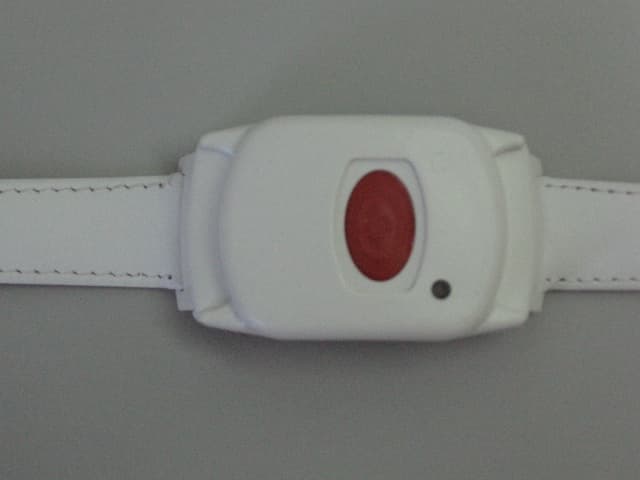
GSAWPK250
Jun 03, 2007PANIC WATCH
Equipment Class
DSC - Part 15 Security/Remote Control Transmitter
GSA5-RLE00125B
May 28, 2007LF Exciter
Equipment Class
DCD - Part 15 Low Power Transmitter Below 1705 kHz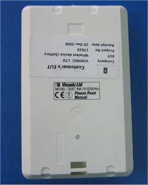
GSADUETAM
May 16, 2007Dual-Technology Microwave/PIR Intrusion Detector
Equipment Class
FDS - Part 15 Field Disturbance Sensor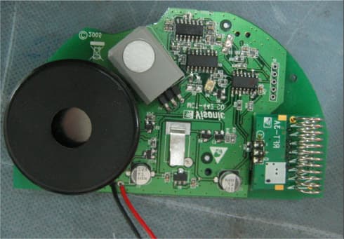
GSAMCT442
May 01, 2007Supervised Indoor Wireless CO Gas Detector
Equipment Class
DSC - Part 15 Security/Remote Control Transmitter