GSASPD1000Wireless Magnetic Displacement Detector
Visonic Inc.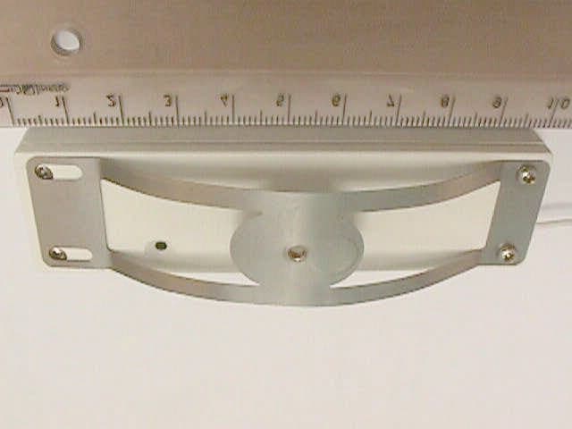
Click to zoom
Application Details
- Equipment Class
- DSR - Part 15 Remote Control/Security Device Transceiver
- Date of Grant
- May 02, 2002
- Application Purpose
- Original Equipment
- Date of Application
- May 02, 2002
- Equipment Note
- Wireless Magnetic Displacement Detector
- Frequency Range
- 315.00000000 - 315.00000000
- Company
- Visonic Inc.
- Country
- United States
Documents & Files
Document Text
Text extracted from the exhibit documents filed with the FCC. Open a document above to read the original.
Users Manual
DE36521 SPD SPDSPD SPD-1000 -1000-1000 -1000 Wireless Magnetic Displacement Detector Installation Instructions 1 11 1. INTRODUCTION . INTRODUCTION. INTRODUCTION . INTRODUCTION SPD-1000 is a fully supervised wireless detector, designed for protection of paintings, sculptures and other artwork, in museums, galleries, churches, private artwork collections, etc. Figure 1 - Integration of SPD-1000 in an Alarm System When someone tries to touch or remove the secured object, to which the detector is attached, an identifiable alarm signal is transmitted to alert security personnel. Identifiable signals include: low battery voltage alert, low severity alarm (slight touch) and high severity alarm (repetitive touch, strong touch or removal). In addition, the detector periodically sends supervision signal as a serviceability report. With PowerArt high level, sensitivity can be extended. The detector has 3 modes: A . ìSleepî - for the detector transport or long term storage, without causing an alarm. In this mode the current consumption is very low. B . ìInstallationî - for sensor's spring active range adjustment and for teaching the SpiderAlert / PowerArt system the detectorís identity. C . ìOperationî. Figure 2 External View All mode changes and alarms are aurally indicated by an integral buzzer. The SPD-1000 has tracking mode (for SpiderAlert only) that enables to track the secured object's location up to 10 minutes after its removal (with SpiderAlert receivers deployed within the site). This option is possible if the detector is attached to the secured object. For a large painting, several SPD-1000 units can be used. 2 22 2. SPECIFICATIONS . SPECIFICATIONS. SPECIFICATIONS . SPECIFICATIONS Movement Detection Sensitivity: 0.1 mm Transmission Frequency (MHz): 315 or 433.92 Compatible Receivers: PowerArt / MCR-308, SpiderAlert SR-500ER / SCP-532ER / SR-520ER. Overall Message Length: 36 bits, including 24-bit identification code, pulse width modulation. Supervision Transmission: Every 60 min. (USA) / 15 min. (Europe) Power Source: Two 3V/160 mAh Lithium batteries, GP CR-2025, or equivalent. Current Consumption: 8 μA (STBY), 8 mA (transmission) Battery Life: 5 years under normal installation conditions Battery Supervision: Automatic transmission of battery condition data as part of any status report. Tracking Transmission: Every 30 sec., while the secured object is being moved from its original place, up to 10 min. after last movement. Operating Temperatures: 0°C to 50°C (32°F to 122°F) Dimensions (HxWxD): 96 x 28 x 22 mm (3-13/16 x 1-1/8 x 7/8 in.) Weight (with battery): 34.8 g (1.2 oz) Color: Housing - white, spring - nickel Compliance with Standards: FCC part 15, IC:1467102181. The term "IC" before the certification/registration number only signifies that the Industry Canada technical specifications were met. 3 33 3. INSTALLATION . INSTALLATION. INSTALLATION . INSTALLATION 3.1 Installation Options Figure 3 - Installation Possibilities 2DE3652 Figure 4 - Using a Bracket to Attach the Detector Attention! Before detector installation: 1 . Remove spring movement prevention sticker (see fig. 5). 2 . Remove protective non-metallic spacer that keeps the spring in the ìsleepî mode (shown in par. 3.7). 3.2 Setting the SMD Switches Figure 5 Switch Setting Method Table 1 - SMD Switches Functions Switch Function Pos.Selected OptionDefault SW. 1 Sensitivity & tracking ON Spider: Tracking enabled PowerArt: High sensitivityON OFF Spider: Tracking disabled PowerArt: Low Sensitivity SW. 2 BuzzerON EnabledON OFF Disabled SW. 3 Supervision ON USA (60 Min.)ON OFF Europe (15 Min.) SW. 4 ModeON SpiderAlertON OFF PowerArt or MCR-308 3.3 Preparation for Use 3.4 Teaching PowerArt / MCR-308 Teach PowerArt / MCR-308 to identify SPD-1000: A . Teach PowerArt (see par. 3.2G in PowerArt Prog. Guide) or MCR-308 (see par. 3.5 in MCR-308 installation instructions). When instructed to transmit, initiate SPD-1000 low severity alarm transmission by momentarily pressing the Reset switch (see illustration 1 in par. 3.3). Note: According to this signal, the PowerArt automatically learns to identify high severity alarm, low severity alarm, low battery and supervision messages. According to this signal the MCR-308 learns to identify low severity alarm only. To teach the MCR-308 the high severity alarm, create the alarm after the detector has been stabilized, by strong movement / removal of the secured object. B . Verify that the teaching is successful, according to the previously mentioned documents. 3.5 Teaching the SpiderAlert System Teach SpiderAlert system to identify SPD-1000 transmissions: A . In SpiderAlert software Click File/Transmitters/Museum/Add. B . Initiate low severity alarm transmission by momentarily pressing Reset switch (see par. 3.3, step 1). C . The detectorís ID number will be displayed in the yellow box. D . Press the ì<<î button to move the ID number from the yellow (temporary) box to the ìIDî box. E . In the Location box, type the secured object's name (i.e. Mona Liza picture). F . In Holder Group box, type a desired name for the museum detectors group for whom the event handling will be identical. G . Press the button, to display the Museum Group screen. H . Select the appropriate museum detectors group. I . Press Edit button, define (for the operator) the handling description for every detectorís event and press OK. 3.6 Operation SPD-1000 function is based on magnetic field changes as a result of the secured object movements. The detector has 2 detection levels - low severity alarm (continuous slight touch) and high severity alarm (strong touch or removal). Once stabilized, the detector checks its position continuously. Upon a movement detection, the detector sends alarm as follows: Note: After HIGH alarm only, the detector needs 90-second stabilization period at least, for the next movement detection. When Low or High level alarm is transmitted, 2 weak buzzer sounds are heard, as shown. 3.7 Entering the ìSleepî M…
Text truncated - open the document above for the full version.
Block Diagram
SPD 1000 Block Diagram An oscillating circuit constructed of a coil 24 with a core and capacitors 26 and 28, generate with the microprocessors internal clocking circuitry 22 a clocking signal for the microprocessor. This clock signal is substantially affected by inductance change of the coil 24. For example a magnet 32 in the proximity of the coil 24 will affect the working point of the coil core and change the coil inductance. As a result the frequency of the clock signal of the microprocessor will vary. The sensor is based on measuring and analyzing this frequency change in conjunction with a change of displacement of a constant magnet 32 in the proximity of the coil 24. Circuit 40 supplies the time base for conducting calculations as for the temporal variations in frequency. 42 44 Micro - Processor 16 Fig. 2 22 26 24 28 N S 32 40 30 OSC1 OSC2 I/O counter 48
Cover Letter(s)
April 7, 2002 American TCB 6731 Whittier Ave Suite C110 McLean, VA 22101 USA Subject: Application for certification of wireless displacement detector, model: SPD 1000 FCC @ 315 MHz, FCC ID: (GSASPD1000) Dear Gentlemen, Please find attached our application for certification of wireless displacement detector, FCC ID: GSASPD1000 (Changed for GSARFT1A), prepared in accordance with FCC Rules, parts 15 and 2. The product testing and this application for certification were performed by Hermon Laboratories, which is listed by FCC. Hermon Labs responsible person is Mr. Gonen Usishkin, tel: 011 972 4628 8001, fax:011 972 4628 8277, e-mail: [email protected] . Please send an invoice to Hermon Labs. We hope this application satisfies your requirements Yaacov Kotlicki Directing Manager Head Office 30 Habarzel Street Tel Aviv 69710 Israel Postal Address P.O.B. 22020 Tel Aviv 61220 Israel Tel 972 3 6456789 Fax 972 3 6456788
Cover Letter(s)
American Telecommunications Certification Body Inc. 6731 Whittier Ave, McLean, VA 22101 April 15, 2002 RE: FCC ID: GSARFT1A I have a few comments on this Application. 1 The instruction/manual does not contain the warning statement about not modifying the device. Please include the non-modification statement in accordance with CFR47 15.21. 2 There is no indication that the device transmits under the 5-sec time constraint of 15.231. The device appears to function automatically during alarm conditions, however, “A transmitter activated automatically shall cease transmission within 5 seconds after activation.” Please verify that the device meets this requirement. 3 While the manual states that supervisory transmissions occur once every 60 minutes, there is no indication as to how long the transmitter is on during this supervisory condition. This supervisory transmission is limited to no more than one second during on hour. Switch 3 is an on/off toggle switch that selects a 15 min or one hour supervisory mode. The supervisory mode in the US can ONLY BE FOR ONE SECOND IN 60 MINUTES. Please explain how this switch is made inaccessible for use in the US. Or, please explain how this device is limited to one second TOTAL transmit time within the one hour limit for 15.231. For example, a timed 250ms transmission every 15 minutes would meet the one second total transmit time in one hour. 4 The instruction/manual states that there is a ‘tracking’ mode. Please show how this tracking mode does not violate the 5-second transmission limitation or the other data/time limitations of 15.231. Dennis Ward mailto:[email protected] The items indicated above must be submitted before processing can continue on the above referenced application. Failure to provide the requested information may result in application termination. Correspondence should be considered part of the permanent submission and may be viewed from the Internet after a Grant of Equipment Authorization is issued. Please do not respond to this correspondence using the email reply button. In order for your response to be processed expeditiously, you must submit your documents through the AmericanTCB.com website. Also, please note that partial responses increase processing time and should not be submitted. Any questions about the content of this correspondence should be directed to the sender.
Cover Letter(s)
To overcome message collisions at the receiving end, PowerCode transmitters transmit 3 data bursts at random intervals, with 6 repetitions of the same message in each burst (Fig. A2). This redundancy improves the probability of reception. Figure A2
Cover Letter(s)
Subject: GSARFT1A Date: Sun, 28 Apr 2002 11:47:27 +0200 From: Valeria Mednikov <[email protected]> To: "'[email protected]'" <[email protected]> In reply to e-mail dated April 15, 2002 Dear Mr. Ward, Below are the answers to your questions. FCC ID: GSARFT1A 1. Please find an updated version of Installation Instructions with the non-modification statement, submitted via "Add to existing application", User's Manual folder on April 28, 2002. 2. The explanation of Arick Elshtein (Visonic): The duration of the alarm message is less that 5 seconds, this is provided by using PowerCode. Please find the description of this code in PPROTOCOL_POWERCODE file, submitted via "Add to existing application", Additional information folder on April 28, 2002. The explanation of Arick Elshtein (Visonic): After the initial alarm message, the unit is "dead/quiet" for 90 to 120 seconds, after which if there is again an alarm trigger, it will send again the alarm message. I do not see this as if the device functions automatically, since IT IS TRIGGERED BY EXTERNAL EVENT. Also, please remember that there are 3 levels of alarm triggering LOW, HIGH and picture removal. A picture removal alarm is automatically followed by a tracking mode. 3. The explanation of Arick Elshtein (Visonic): The supervision transmission is two consecutive bursts of total duration 285X2 milliseconds. This burst is repeated every hour. This duration is of no consequence to the user, so it is not mentioned in the manual. Since Europe requires supervision every 15 minutes, this option is included, but not used in USA. For the USA version (315 MHz), we shall disable the possibility of 15 minutes by hard wiring this position. 4. The explanation of Arick Elshtein (Visonic): Tracking is a special kind of alarm. If the unit is set to tracking mode, then after an alarm a message/burst of 280 milliseconds is repeated every 30 seconds for about 20 times. Hope, you find these answers satisfactory. With great respect, Valeria
External Photos
SPD-1000 top view SPD-1000 bottom view
ID Label/Location Info
SPD 1000 LABEL The identification label (material –polyester) is affixed on the device rear side. The drawing is shown on the next page.
Internal Photos
SPD-1000 internal view (first side) SPD-1000 internal view (second side)
Operational Description
DE3652 1 SPD-1000 Wireless Magnetic Displacement Detector Technical description 1. INTRODUCTION SPD-1000 is a fully supervised wireless detector, designed for protection of paintings, sculptures and other artwork, in museums, galleries, churches, private artwork collections, etc. Figure 1 - Integration of SPD-1000 in an Alarm System When someone tries to touch or remove the secured object, to which the detector is attached, an identifiable alarm signal is transmitted to alert security personnel. Identifiable signals include: low battery voltage alert, low severity alarm (slight touch) and high severity alarm (repetitive touch, strong touch or removal). In addition, the detector periodically sends supervision signal as a serviceability report. With PowerArt high level, sensitivity can be extended. The detector has 3 modes: 1st.“Sleep” - for the detector transport or long term storage, without causing an alarm. In this mode the current consumption is very low. 2nd.“Installation” - for sensor's spring active range adjustment and for teaching the SpiderAlert / PowerArt system the detector’s identity. 3rd.“Operation”. Figure 2 External View All mode changes and alarms are aurally indicated by an integral buzzer. The SPD-1000 has tracking mode (for SpiderAlert only) that enables to track the secured object's location up to 10 minutes after its removal (with SpiderAlert receivers deployed within the site). This option is possible if the detector is attached to the secured object. For a large painting, several SPD-1000 units can be used. 2. SPECIFICATIONS Movement Detection Sensitivity: 0.1 mm Transmission Frequency (MHz): 315 or 433.92 Compatible Receivers: PowerArt / MCR-308, SpiderAlert SR- 500ER / SCP-532ER / SR-520ER. Overall Message Length: 36 bits, including 24-bit identification code, pulse width modulation. Supervision Transmission: Every 60 min. (USA) / 15 min. (Europe) Power Source: Two 3V/160 mAh Lithium batteries, GP CR- 2025, or equivalent. Current Consumption: 8 μA (STBY), 8 mA (transmission) Battery Life: 5 years under normal installation conditions Battery Supervision: Automatic transmission of battery condition data as part of any status report. Tracking Transmission: Every 30 sec., while the secured object is being moved from its original place, up to 10 min. after last movement. Operating Temperatures: 0°C to 50°C (32°F to 122°F) Dimensions (HxWxD): 96 x 28 x 22 mm (3-13/16 x 1-1/8 x 7/8 in.) Weight (with battery): 34.8 g (1.2 oz) Color: Housing - white, spring - nickel Compliance with Standards.: FCC part 15, CAN 1467102181 Operation SPD-1000 function is based on magnetic field changes as a result of the secured object movements. The detector has 2 detection levels - low severity alarm (continuous slight touch) and high severity alarm (strong touch or removal). Once stabilized, the detector checks its position continuously. Upon a movement detection, the detector sends alarm as follows: Note: After HIGH alarm only, the detector needs 90-second stabilization period at least, for the next movement detection. When Low or High level alarm is transmitted, 2 weak buzzer sounds are heard, as shown. Compliance with Standards This device complies with FCC Rules Part 15. Operation is subject to two conditions: (1) This device may not cause harmful interference, and (2) this device must accept any interference that may be received or that may cause undesired operation. The 315 MHz is for USA & Canada - not allowed in any EU member state. The 433.92 MHz has no restriction in any EU member state.
RF Exposure Info
Environmental evaluation and exposure limit according to FCC CFR 47part 1, §1.1307, §1.1310 Limit for power density for general population/uncontrolled exposure is 0.21 mW/cm 2 . P T The power density P (mW/cm 2 ) = ------------- , where 4π r 2 P T is the maximum equivalent isotropically radiated power (EIRP). In our case P T is –19.64 dBm = 0.01 mW. 0.21(mW/cm 2 ) = 0.01 mW / 4π r 2 The minimum safe distance “r”, where RF exposure does not exceed FCC permissible limit, is 0.06 cm. r = sqrt(P T / (Px4 π )) = sqrt(0.01 / (0.21 x 4 x 3.14)) = 0.06 (cm). Hence, no safety hazard exists for human being.
Test Report
This report is in conformity with ISO/IEC 17025. The A2LA logo endorsement applies only to the test methods and the standards that are listed in the scope of Hermon Laboratories accreditation. The test results relate only to the items tested. This test report must not be reproduced in any form except in full with the approval of Hermon Laboratories Ltd. Page 1 of 23 Document ID: visrad_fcc.14957.doc Date of Issue: February 02 HERMON LABORATORIES Electrical Hermon Laboratories Ltd. P.O.Box 23 Binyamina 30550, Israel Tel.+972 66288001 Fax.+972 66288277 e-mail: [email protected] RADIO TEST REPORT ACCORDING TO 47 CFR Part 15 SUBPART C §15.231, §15.205, §15.209 and SUBPART B; RSS-210 Issue 5:2001; ICES-003 Issue 3:1997 for VISONIC Ltd. EQUIPMENT UNDER TEST: Product: wireless displacement detector Brand name: SPD 1000 Model: SPD 1000 FCC @ 315 MHz Page 2 of 23 Document ID: visrad_fcc.14957.doc Date of Issue: February 02 HERMON LABORATORIES Contents CONTENTS.............................................................................................................................................................................. 2 1 PROJECT INFORMATION .............................................................................................................................................. 3 2 SUMMARY OF TESTS AND REQUIREMENTS .............................................................................................................. 4 3 EUT DESCRIPTION ......................................................................................................................................................... 6 3.1 G ENERAL DESCRIPTION ................................................................................................................................................ 6 3.2 EUT TEST CONFIGURATION .......................................................................................................................................... 6 3.3 T RANSMITTER DESCRIPTION .......................................................................................................................................... 7 4 TEST RESULTS............................................................................................................................................................... 8 4.1 B ANDWIDTH OF EMISSION ACCORDING TO § 15.231 ( C ) AND RSS-210 § 6.1.1( C ) ............................................................ 8 4.2 F IELD STRENGTH OF FUNDAMENTAL , § 15.231 AND RSS-210 § 6.1.1( B )......................................................................... 9 4.3 F IELD STRENGTH OF SPURIOUS RADIATION , § 15.231 AND RSS-210 § 6.1.1( B ) ............................................................. 10 4.4 U NINTENTIONAL RADIATED EMISSIONS TEST ACCORDING TO §15.109 AND ICES-003....................................................... 11 APPENDIX A - PLOTS .......................................................................................................................................................... 12 APPENDIX B – TEST SETUP PHOTOGRAPHS................................................................................................................... 17 APPENDIX C - TEST EQUIPMENT USED FOR TESTS ....................................................................................................... 21 APPENDIX D - GENERAL INFORMATION........................................................................................................................... 22 T EST FACILITY DESCRIPTION ................................................................................................................................................... 22 A BBREVIATIONS AND ACRONYMS ............................................................................................................................................. 22 S PECIFICATION REFERENCES .................................................................................................................................................. 22 FCC E QUIPMENT CODES AND DESCRIPTIONS ........................................................................................................................... 23 Page 3 of 23 Document ID: visrad_fcc.14957.doc Date of Issue: February 02 HERMON LABORATORIES 1 Project information Description of equipment under test Test items : Wireless displacement detector Manufacturer : VISONIC Brand name : SPD 1000 Equipment serial number : Cat No 1-3652-2 Types (Models) : 315 MHz Software revision(s) of radio unit as tested : Rev 3 Equipment FCC code 1 : DSC Applicant information Applicant’s responsible person : Mr. Arick Elshtein Company : Visonic Address : 27 Habarzel Street Postal code : 69710 City : Tel Aviv Country : Israel Telephone number :+972 3 6456714 Telefax number :+972 3 6456891 Test performance Project Number: :14957 Location :Hermon Laboratories Receipt date :January 13, 2002 Test started :January 13, 2002 Test completed : Purpose of test Apparatus compliance verification in accordance with emission requirements Test specification(s) 47CFR Part 15, subpart C, §15.231, §15.205, §15.209, and subpart B §15.107, §15.109; RSS-210 Issue 5: 2001 and ICES-003 Issue 3: 1997 1 FCC Equipment codes – see Appendix D Page 4 of 23 Document ID: visrad_fcc.14957.doc Date of Issue: February 02 HERMON LABORATORIES Hermon Laboratories Ltd. P.O.Box 23 Binyamina 30550, Israel Tel.+972 66288001 Fax.+972 66288277 e-mail: [email protected] 2 Summary of tests and requirements Parameter Subclause C NC NT NA Tested by Date tested Remarks Transmitter characteristics, §15.231 Periodic operation 15.231(a) X Refer to Installation instructions Bandwidth of emission 15.231(c) X Mr. A. Troupiansky, test engineer January 22, 2002 Field strength of fundamental 15.231(b)(2) X Mr. Y. Neuman, test engineer January 16, 2002 Field strength of spurious radiation 15.231(b)(3) X Mr. A. Troupiansky, test engineer January 22, 2002 Unintentional radiation…
Text truncated - open the document above for the full version.
Test Setup Photos
Unintentional radiated emission measurements with double ridged guide antenna (frequencies above 1 GHz) Unintentional radiated emission measurements Unintentional radiated emission measurements log periodic antenna (frequencies 200 MHz - 1 GHz) Fundamental and spurious emission measurements at OATS
Contact Information
Applicant
Scott Jensen(Tec Manager)
860-243-0833
Technical Contact
Hermon LaboratoriesEdward Usoskin
[email protected]972-4-628-8001
Harakevet Industrial Zone · Binyamina · Israel
Non-Technical Contact
Visonic LtdArick Elshtein
[email protected]972-3-6456714
Test Firm
Hermon Laboratories Ltd.Alexander Usoskin
Technical Specifications
| # | Rule Parts | Frequency Range | Power Output |
|---|---|---|---|
| 1 | 15C | 315 MHz - 315 MHz | - |
Other Applications from Visonic Inc.

GSA5-BTC00433
Nov 14, 2007Infant Protection Bracelet
Equipment Class
DSC - Part 15 Security/Remote Control Transmitter
GSAWPK250
Jun 03, 2007PANIC WATCH
Equipment Class
DSC - Part 15 Security/Remote Control Transmitter
GSA5-RLE00125B
May 28, 2007LF Exciter
Equipment Class
DCD - Part 15 Low Power Transmitter Below 1705 kHz
GSADUETAM
May 16, 2007Dual-Technology Microwave/PIR Intrusion Detector
Equipment Class
FDS - Part 15 Field Disturbance Sensor
GSAMCT442
May 01, 2007Supervised Indoor Wireless CO Gas Detector
Equipment Class
DSC - Part 15 Security/Remote Control Transmitter