GSAVXS10Single Door Access Control System
Visonic Inc.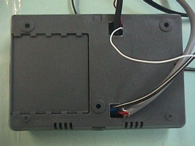
Click to zoom
Application Details
- Equipment Class
- DCD - Part 15 Low Power Transmitter Below 1705 kHz
- Date of Grant
- Feb 01, 2000
- Application Purpose
- Original Equipment
- Date of Application
- Jan 04, 2000
- Equipment Note
- Single Door Access Control System
- Frequency Range
- 0.12500000 - 0.12500000
- Company
- Visonic Inc.
- Country
- United States
Documents & Files
Document Text
Text extracted from the exhibit documents filed with the FCC. Open a document above to read the original.
Users Manual
Sales: 30 Habarzel Street, Tel Aviv 69710 Israel Tel : 972 3 6456789, Fax 972 3 6456891 Technical Dept.: 35 Hamelacha St. Carmiel 20100 Tel: 972 4 9081115 Fax: 972 4 9081116 1 VXS-10 User Guide pp.2-5 VXS-10 Installation Guide pp.6-11 2 VXS-10 User Guide 1. Introduction Thank you for choosing the VisAccess VXS-10. We are confident that this product will serve your needs for years to come. The VisAccess VXS-10 is an electronic access control solution for a single access point, such as a main door in an apartment building or individual office doors. The controller relay activates a lock or electromagnetic strike (EMS), when a valid proximity key (tag) is presented to the reader located outside the protected area. The use of a proximity (non-contact) key makes the installation of the VXS-10 system an attractive possibility in harsh environments and in places with poor lighting conditions. The proximity keys are totally sealed and wear resistant. The lock reads the key’s ID, whenever the key is presented close to the reader. The VXS-10 proximity controller is composed of a three-digit display, three visual indicators (LED) and four buttons. An internal proximity reader located in the upper right corner of the panel allows fast and easy programming of access keys. The buttons are used for entering the password and for programming the unit. The VXS-10 has a memory capacity of 300 keys. Adding keys simply involves presenting new keys to the proximity reader while in the ADD mode. The user can delete keys in the DELETE mode by presenting them to the reader or, if a key is unavailable, by typing in its number (the same one that appears when adding the key). Additional special features are also programmable from the control panel. 2. User Programming 2.1. Entering The Programming Menu Note: Inactivity for more than 10 seconds will cause VXS-10 to exit the programming menu. The VXS-10 recognizes one master key and one password. The master key will NOT open the lock. To use the master key for entering the programming menu, press the “MODE” button and then present the master key next to the external or internal reader for 2 seconds. The reason for the 2 seconds delay is to prevent inadvertent activation of the programming menu. The master key will enable the user to select the programming menu and add or delete keys. For setup functions such as “password”, “master key”, “unlock time” or “erase all keys” an additional four-step password is needed. Each step may involve pressing any one of the four keys or a combination of two keys. Altogether, there are 10,000 passwords possible (see “2.8. Setting Password”). The master key is also used to confirm changes made to parameters. The VXS-10 is shipped from the factory with the following default password: F3 1 F3 1 F3 1 F3 1 Note: While in any one of the programming modes, the VXS-10 will not operate the EMS. 3 2.2. Selecting The Programming Mode The VXS-10 recognizes 6 programming modes: • Adding User Keys • Deleting User Keys • Erasing All User Keys • Setting Unlock Time • Setting Password • Setting Master Key To select the programming mode, press the “MODE” button and present the master key to the reader until the green light (ADD light) starts flashing for at least 2 seconds. Press the “MODE” button to choose between Add, Delete and Special Operations. Adding User Keys is possible when the ADD light is ON. Deleting User Keys is possible when the DELETE light is ON. Set-up functions are changed when the SPECIAL light is ON. For set-up functions, enter the user’s password and select the desired option with the “MODE” button. Erase All User Keys - “Er” will be displayed. Set Unlock Time - “UL” will be displayed. Set Master Key - “S0” will be displayed. Set Password - “PP” will be displayed. 2.3. Adding User Keys Note: It is recommended to keep a list of key-holder names and keys serial numbers, in order to be able to delete stolen or lost keys. • To select the ADD mode press the “MODE” button and present the master key to the reader until the ADD LED starts flashing, indicating that the VXS-10 is ready to add a key. • Once you present a key to the internal reader, the key will be added and its number will be displayed for a few seconds. • Write down the number and the key holder’s name for future reference. • After a few seconds the green LED will flash indicating that the system is ready for adding the next key. • Press the “MODE” button for the next programming mode or simply wait 5 seconds for the system to time out and revert to normal operation. 2.4. Deleting User Keys To select the DELETE mode press the “MODE” button and present the master key to the reader until the “ADD” LED starts flashing, then press “MODE” again. The DELETE light will start flashing to indicate that the system is ready to delete a key. Deleting keys can be accomplished in two ways: • If you have the key to be deleted, present it to the reader. The key number will be displayed for a few seconds and then the numeric display will blank to indicate readiness for the next operation. • To delete a missing key, press the “100”,“10” and “1” buttons until you reach the key number you wish to delete. For example, to indicate the number 143, press the “100” button once, then press the “10” button four times then press the “1” button 3 times. Once the number is set, present the master key or press the “MODE” button to acknowledge the operation. Hold the master key until the key number disappears from the numeric display and 4 the red LED is ON. The red LED will start blinking again to indicate that the system is ready for deleting the next key. Press the “MODE” button for the next programming mode or simply wait 5 seconds for the system to time out and revert to normal operation. 2.5. Erasing ALL User Keys • To select the ERASE ALL mode press the “MODE” button and present the master key to the reader until the ADD light starts blinking. • Press “MODE” twice until the “SPECIAL” LED goes ON. …
Text truncated - open the document above for the full version.
Block Diagram
VXS-10 Controller Microprocessor PIC16C6X EEPROM Relay 5V power supply 10-14Vdc/ac input Dry contact relay (max 2A) with optional 10-14V supply VXS-10 Functional Block Diagram Tri-color LED Mode F3F2F1 Buttons 7-segment display VisAccess VisAccessVisAccess VisAccess Head office 30 Habarzel Street, Tel Aviv 69710 Israel Tel 972 3 6456789, Fax 972 3 6456788 Technical 35 Hamelacha Street, Karmiel 20100 Israel Tel 972 4 9081115, Fax 972 4 9081116 RDR-3 antenna RFID front end circuitry (125KHz)
Cover Letter(s)
VisAccess VisAccessVisAccess VisAccess Head office 30 Habarzel Street, Tel Aviv 69710 Israel Tel 972 3 6456789, Fax 972 3 6456788 Technical 35 Hamelacha Street, Karmiel 20100 Israel Tel 972 4 9081115, Fax 972 4 9081116 January 4, 2000 FEDERAL COMMUNICATIONS COMMISSION EQUIPMENT APPROVAL SERVICES P.O.B. 358315 Pittsburgh, PA 15251-5315 USA Subject: Application for certification of Single door access control system, model VXS-10, FCC ID:GSAVXS10 Dear Gentlemen, Please find attached our application for certification of Single door access control system, model VXS-10, FCC ID:GSAVXS10, prepared in accordance with FCC Rules, parts 2 and 15. The product testing and this application for certification were performed by Hermon Laboratories, which is listed by FCC. Hermon Labs responsible person is Dr. Edward Usoskin, tel: 01197266288001, fax:01197266288277, e-mail: [email protected]. We hope this application satisfies your requirements. Sincerely yours, Arick Elshtein, technical support manager VisAccess Ltd.
External Photos
VXS-10 Controller external top view VXS-10 Controller external bottom view VXS-10 Reader RDR-3 external view
Internal Photos
VXS-10 Controller, PC board, front view VXS-10 Controller, PC board, rear view VXS-10 Reader RDR-3, component side VXS-10 Reader RDR-3, print side
Operational Description
Technical Department 35 Hamelacha Street, Karmiel 20100 Israel P.O.B. 6257, Karmiel 20100 Israel Tel 972 4 9081115, Fax 972 4 9081116 Sales Office 30 Habarzel Street, Tel Aviv 69710 Israel Tel 972 3 6456789, Fax 972 3 6456788 VXS-10+RDR-3 functional description The VXS-10 system is comprised of two circuit boards: • Controller • External Reader The controller contains a micro-controller, which handles all inputs and outputs, including reading a key tag, handling non-volatile memory and opening the lock. The External Reader contains two sections: 1. Voltage regulator 2. RFID front end The VXS-10 works off 12V ±2V. it has an internal 5V voltage regulator for powering the logic section of the circuitry (CPU, memory). A relay is used as a dry contact to operate an electromechanical lock, which is connected to the unit. The CPU is a Microchip PIC micro-controller which supervises a few inputs: • RFID signal – comes from the RFID section. • DIP switch. • Four buttons used for programming the system. A valid key tag code will be compared to up to 300 memory locations in the EEPROM. If key tag code is equal to master key, the VXS-10 will wait to see if key is held in place for 10 seconds. If it is, it enters the programming mode. If the key tag is not the master key, the VXS-10 scans the entire memory. If the key is found in memory, the green light is turned on, and the relay is closed to open the lock. If the key is not found, the red light will be turned on. The RFID front end section is a standard VisAccess design based on the Temic 2270 device. The 2270 is used for generating a 125KHz carrier on the antenna and filtering the key tag code. The carrier frequency is maintained across the temperature range by using a few accurate capacitors (200V NPO 2% or 5%). The antenna is a rectangular 54mm x 75mm air coil with a rating of approx. 1.2mH @ 1000Hz. The field generated by the front end using the antenna provides the CPU with key tag code to a maximum distance of 10cm.
Test Report
VISRAD_FCC.13644.doc Date: November, 1999 FCC ID:GSAVXS10 Page 1 of 33 HERMON LABORATORIES ELECTROMAGNETIC EMISSIONS TEST REPORT ACCORDING TO FCC PART 15, SUBPART C, §15.209 FOR VISACCESS Ltd. EQUIPMENT UNDER TEST SINGLE DOOR ACCESS CONTROL SYSTEM model VXS-10 Prepared by: _________________ Mrs. M. Cherniavsky, certif. engineer Hermon Labs Approved by: _________________ Mr. A. Usoskin, QA manager Hermon Labs Approved by: _________________ Mr. Arick Elshtein, technical support manager Visaccess Ltd. Hermon Laboratories Ltd. P.O.Box 23 Binyamina 30550, Israel Tel.+972-6628-8001 Fax.+972-6628-8277 Email:[email protected] Electrical VISRAD_FCC.13644.doc Date: November, 1999 FCC ID:GSAVXS10 Page 2 of 33 HERMON LABORATORIES Description of equipment under test Test items Access control system, FCC ID:GSAVXS10 Manufacturer Visaccess Ltd. Brand Mark Visaccess Ltd. Type (Model) VXS-10 Applicant information Applicant’s representative & responsible person Mr. Arick Elshtein, technical support manager Company Visaccess Ltd. Address 30 Habarzel St. P.O. Box 22020 Postal code 61220 City Tel Aviv Country Israel Telephone number +972 3645 6714 Telefax number +972 3645 6743 Test performance Project Number 13644 Location of the test Hermon Laboratories, Binyamina, Israel Test started September 21, 1999 Test completed September 21, 1999 Purpose of test The EUT certification in accordance with CFR 47, part 2, §2.1033 Test specification(s) FCC part 15, subpart C, §15.209, §15.207 subpart B, §15.109 The A2LA logo endorsement applies only to the test methods and the standards that are listed in the scope of Hermon Laboratories accreditation by A2LA. Through this report period is used as decimal separator while thousands are separated by comma. This report is in conformity with EN 45001 and ISO GUIDE 25. The test results relate only to the items tested. This test report must not be reproduced in any form except in full, with the approval of Hermon Labs Ltd. VISRAD_FCC.13644.doc Date: November, 1999 FCC ID:GSAVXS10 Page 3 of 33 HERMON LABORATORIES Table of Contents 1 GENERAL INFORMATION.....................................................................................................................4 1.1 ABBREVIATIONS AND ACRONYMS.............................................................................................................4 1.2 SPECIFICATION REFERENCES......................................................................................................................5 1.3 EUT DESCRIPTION....................................................................................................................................5 2 TEST FACILITY DESCRIPTION.............................................................................................................7 2.1 GENERAL..................................................................................................................................................7 2.2 EQUIPMENT CALIBRATION........................................................................................................................7 2.2.1 Expanded uncertainty at 95% confidence in Hermon Labs EMC measurements...............7 2.3 LABORATORY PERSONNEL........................................................................................................................8 2.4 STATEMENT OF QUALIFICATION...............................................................................................................8 3 RADIATED EMISSION MEASUREMENTS..........................................................................................9 3.1 FIELD STRENGTH OF EMISSIONS ACCORDING TO § 15.209 (A)..................................................................9 3.1.1 Specified limit...............................................................................................................................9 3.1.2 Extrapolation (distance correction) factor...............................................................................9 3.1.3 Test procedure..............................................................................................................................9 3.2 UNINTENTIONAL RADIATED EMISSIONS TEST ACCORDING TO §15.109..................................................16 3.2.1 General.......................................................................................................................................16 3.2.2 Test procedure...........................................................................................................................16 3.3 CONDUCTED EMISSION MEASUREMENTS ACCORDING TO §15.107, §15.207........................................22 3.3.1 General.......................................................................................................................................22 3.3.2 Test procedure...........................................................................................................................22 4. SUMMARY AND SIGNATURES...........................................................................................................29 APPENDIX A – TEST EQUIPMENT AND ANCILLARIES USED FOR TESTS..................................30 APPENDIX B-TEST EQUIPMENT CORRECTION FACTORS.............................................................31 VISRAD_FCC.13644.doc Date: November, 1999 FCC ID:GSAVXS10 Page 4 of 33 HERMON LABORATORIES 1 General information 1.1 Abbreviations and acronyms The following abbreviations and acronyms are applicable to this test report: AC alternating current BW bandwidth dB decibel dBm decibel referred to one milliwatt dB(μV) decibel referred to one microvolt dB(μV/m) decibel referred to one microvolt per meter DC direct current EUT equipment under test GHz gigahertz H height HL Hermon Laboratories Hz hertz IF intermediate frequency kHz kilohertz L length m meter mm millimeter MHz megahertz msec millisecond NA not applicable NARTE National Association of Radio and Telecommunications En…
Text truncated - open the document above for the full version.
Contact Information
Applicant
Scott Jensen(Tec Manager)
860-243-0833
Technical Contact
Hermon LaboratoriesEdward Usoskin
[email protected]+972 66288001
HaRakevet Industrial Zone · Binyamina · Israel
Non-Technical Contact
VisaccessArick Elshtein
[email protected]+972 36456789
Test Firm
Hermon Laboratories Ltd.Alexander Usoskin
Technical Specifications
| # | Rule Parts | Frequency Range | Power Output |
|---|---|---|---|
| 1 | 15C | 0.125 MHz - 0.125 MHz | - |
Other Applications from Visonic Inc.

GSA5-BTC00433
Nov 14, 2007Infant Protection Bracelet
Equipment Class
DSC - Part 15 Security/Remote Control Transmitter
GSAWPK250
Jun 03, 2007PANIC WATCH
Equipment Class
DSC - Part 15 Security/Remote Control Transmitter
GSA5-RLE00125B
May 28, 2007LF Exciter
Equipment Class
DCD - Part 15 Low Power Transmitter Below 1705 kHz
GSADUETAM
May 16, 2007Dual-Technology Microwave/PIR Intrusion Detector
Equipment Class
FDS - Part 15 Field Disturbance Sensor
GSAMCT442
May 01, 2007Supervised Indoor Wireless CO Gas Detector
Equipment Class
DSC - Part 15 Security/Remote Control Transmitter