GSAVXS5Proximity Access Control Unit
Visonic Inc.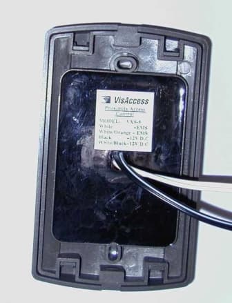
Click to zoom
Application Details
- Equipment Class
- DCD - Part 15 Low Power Transmitter Below 1705 kHz
- Date of Grant
- Feb 15, 2000
- Application Purpose
- Original Equipment
- Date of Application
- Nov 15, 1999
- Equipment Note
- Proximity Access Control Unit
- Frequency Range
- 0.12500000 - 0.12500000
- Company
- Visonic Inc.
- Country
- United States
Documents & Files
Document Text
Text extracted from the exhibit documents filed with the FCC. Open a document above to read the original.
Block Diagram
FCC ID:GSAVXS5 Date: November, 1999 Project number:13665Page 1 of 2 BLOCK DIAGRAM FCC ID:GSAVXS5 Date: November, 1999 Project number:13665Page 2 of 2 Microprocessor PIC16C3 EEPROM antenna Power transistor 5V power supply 10-14Vdc input 10-14Vdc/0.5A max outpu automatic fuse RFID front end circuitry (125KHz) VXS-5 Functional Block Diagram
Cover Letter(s)
VisAccess Ltd November 16, 1999 FEDERAL COMMUNICATIONS COMMISSION EQUIPMENT APPROVAL SERVICES P.O.B. 358315 Pittsburgh, PA 15251-5315 USA Subject: Application for certification of proximity access control unit, operating at 125 kHz, FCC ID:GSAVXS5 Dear Gentlemen, Please find attached our application for certification of proximity access control unit, model VXS-5, FCC ID:GSAVXS5, prepared in accordance with FCC Rules, parts 2 and 15. The product testing and this application for certification were performed by Hermon Laboratories, which is listed by FCC. Hermon Labs responsible person is Dr. Edward Usoskin, tel: 01197266288001, fax:01197266288277, e-mail: [email protected]. We hope this application satisfies your requirements. Sincerely yours, Arick Elshtein, technical support manager VisAccess Ltd. Head Office 30 Habarzel Street Tel Aviv 69710 Israel Postal Address P.O.B. 22020 Tel Aviv 61220 Israel Tel 972 3 6456789 Fax 972 3 6456788
External Photos
FCC ID:GSAVXS5 Date: November, 1999 Project number:13665Page 1 o3 EXTERNAL PHOTOGRAPHS This document contains 2 photographs FCC ID:GSAVXS5 Date: November, 1999 Project number:13665Page 2 o3 Photograph No.1 VXS-5 unit general view FCC ID:GSAVXS5 Date: November, 1999 Project number:13665Page 3 o3 Photograph No.2 VXS-5 case back side view
ID Label/Location Info
FCC ID:GSAVXS5 Date: November, 1999 Project number:13665 Page 1 of 1 LABEL The label shown below is affixed on the bottom of the VXS-5 proximity control access unit. The FCC part 15, §15.19 statement is placed in User Manual. Label placement on the EUT bottom Label
Internal Photos
FCC ID:GSAVXS5 Date: November, 1999 Project number:13665Page 1 of 5 INTERNAL PHOTOGRAPHS This document contains 4 photographs FCC ID:GSAVXS5 Date: November, 1999 Project number:13665Page 2 of 5 Photograph No.1 VXS-5 unit internal view FCC ID:GSAVXS5 Date: November, 1999 Project number:13665Page 3 of 5 Photograph No.2 VXS-5 unit internal view FCC ID:GSAVXS5 Date: November, 1999 Project number:13665Page 4 of 5 Photograph No.3 VXS-5 unit PCB component side FCC ID:GSAVXS5 Date: November, 1999 Project number:13665Page 5 of 5 Photograph No.4 VXS-5 unit PCB soldered side
Operational Description
FCC ID:GSAVXS5 Date: November, 1999 Project number:13665 Page 1 of 1 OPERATIONAL DESCRIPTION The VXS-5 circuit board contains three main sub-sections: 1. Power supply and power transistor output 2. CPU + memory 3. RFID front end The VXS-5 works off 12Vdc ±2V. it has an internal 5V voltage regulator for powering the logic section of the circuitry (CPU, memory). A power transistor is used to direct up to 500mA of current at close to input voltage to the electromechanical lock, which is connected to the unit. An automatic fuse in series with the transistor protects the unit from over-current due to a possible short on the output or a power hungry locking device. The CPU is a Microchip PIC micro-controller which supervises two inputs: • RFID signal – comes from the RFID section • Programming input – comes from the power- wire going to the locking device. A valid key tag code will be compared to 11 non-volatile memory locations in the EEPROM. If key tag code is equal to master key, the VXS-5 will wait to see if key is held in place for 10 seconds. If it is, it enters the programming mode. If the key tag is not the master key, the VXS-5 scans the next 10 locations. If the key is found in memory, the green light is turned on, and the power transistor is operated to open the lock. If the key is not found, the red light will be turned on. The RFID front end section is a standard VisAccess design based on the Temic 2270 device. The 2270 is used for generating a 125 kHz carrier on the antenna and filtering the key tag code. The carrier frequency is maintained across the temperature range by using a few accurate capacitors (200V NPO 2% or 5%). The antenna is a rectangular 54mm x 75mm air coil with a rating of approx. 1.2 mH @ 1000 Hz. The field generated by the front end using the antenna provides the CPU with key tag code to a maximum distance of 10 cm.
Schematics
FCC ID:GSAVXS5 Date: November, 1999 Project number:13665Page 1 of 2 SCHEMATIC DIAGRAM FCC ID:GSAVXS5 Date: November, 1999 Project number:13665Page 2 of 2
Test Report
VISRAD_FCC.13665.doc Date: November, 1999 FCC ID:GSAVXS5 Page 1 of 30 HERMON LABORATORIES ELECTROMAGNETIC EMISSIONS TEST REPORT ACCORDING TO FCC PART 15, SUBPART C, §15.209 FOR VISACCESS Ltd. EQUIPMENT UNDER TEST PROXIMITY ACCESS CONTROL UNIT model VXS-5 Prepared by: _________________ Mrs. M. Cherniavsky, certif. engineer Hermon Labs Approved by: _________________ Mr. A. Usoskin, QA manager Hermon Labs Approved by: _________________ Mr. Arick Elshtein, technical support manager Visaccess Ltd. Hermon Laboratories Ltd. P.O.Box 23 Binyamina 30550, Israel Tel.+972-6628-8001 Fax.+972-6628-8277 Email:[email protected] Electrical VISRAD_FCC.13665.doc Date: November, 1999 FCC ID:GSAVXS5 Page 2 of 30 HERMON LABORATORIES Description of equipment under test Test items Proximity access control unit, FCC ID:GSAVXS5 Manufacturer Visaccess Ltd. Type (Model) VXS-5 Applicant information Applicant’s representative & Mr. Arick Elshtein, responsible person technical support manager Company Visaccess Ltd. Address 30 Habarzel street P.O. Box 22020 Postal code 61220 City Tel Aviv Country Israel Telephone number +972 3645 6714 Telefax number +972 3645 6743 Test performance Project Number 13665 Location of the test Hermon Laboratories, Binyamina, Israel Test started September 14, 1999 Test completed September 15, 1999 Purpose of test The EUT certification Test specification(s) FCC part 15, subpart C, §15.209, §15.207 subpart B, §15.109 The A2LA logo endorsement applies only to the test methods and the standards that are listed in the scope of Hermon Laboratories accreditation by A2LA. Through this report period is used as decimal separator while thousands are separated by comma. This report is in conformity with EN 45001 and ISO GUIDE 25. The test results relate only to the items tested. This test report must not be reproduced in any form except in full, with the approval of Hermon Labs Ltd. VISRAD_FCC.13665.doc Date: November, 1999 FCC ID:GSAVXS5 Page 3 of 30 HERMON LABORATORIES Table of Contents 1 GENERAL INFORMATION.....................................................................................................................4 1.1 ABBREVIATIONS AND ACRONYMS.............................................................................................................4 1.2 SPECIFICATION REFERENCES......................................................................................................................5 1.3 EUT DESCRIPTION....................................................................................................................................5 2 TEST FACILITY DESCRIPTION.............................................................................................................7 2.1 GENERAL..................................................................................................................................................7 2.2 EQUIPMENT CALIBRATION........................................................................................................................7 2.2.1 Expanded uncertainty at 95% confidence in Hermon Labs EMC measurements...............7 2.3 LABORATORY PERSONNEL........................................................................................................................8 2.4 STATEMENT OF QUALIFICATION...............................................................................................................8 3 RADIATED EMISSION MEASUREMENTS..........................................................................................9 3.1 FIELD STRENGTH OF EMISSIONS ACCORDING TO § 15.209 (A)..................................................................9 3.1.1 Specified limit...............................................................................................................................9 3.1.2 Extrapolation (distance correction) factor...............................................................................9 3.1.3 Test procedure..............................................................................................................................9 3.2 UNINTENTIONAL RADIATED EMISSIONS TEST ACCORDING TO §15.109..................................................16 3.2.1 General.......................................................................................................................................16 3.2.2 Test procedure...........................................................................................................................16 3.3 CONDUCTED EMISSION MEASUREMENTS ACCORDING TO §15.107, §15.207........................................20 3.3.1 General.......................................................................................................................................20 3.3.2 Test procedure...........................................................................................................................20 4. SUMMARY AND SIGNATURES...........................................................................................................26 APPENDIX A – TEST EQUIPMENT AND ANCILLARIES USED FOR TESTS..................................27 APPENDIX B-TEST EQUIPMENT CORRECTION FACTORS.............................................................28 VISRAD_FCC.13665.doc Date: November, 1999 FCC ID:GSAVXS5 Page 4 of 30 HERMON LABORATORIES 1 General information 1.1 Abbreviations and acronyms The following abbreviations and acronyms are applicable to this test report: AC alternating current BW bandwidth dB decibel dBm decibel referred to one milliwatt dB(μV) decibel referred to one microvolt dB(μV/m) decibel referred to one microvolt per meter DC direct current EUT equipment under test GHz gigahertz H height HL Hermon Laboratories Hz hertz IF intermediate frequency kHz kilohertz L length m meter mm millimeter MHz megahertz msec millisecond NA not applicable NARTE National Association of Radio and Telecommunications Engineers, Inc. Ω Ohm QP quasi-peak (detector) RBW resolution bandwidth…
Text truncated - open the document above for the full version.
Contact Information
Applicant
Scott Jensen(Tec Manager)
860-243-0833
Technical Contact
Hermon LaboratoriesEdward Usoskin
[email protected]011 972 6628 8001
HaRakevet Industrial Zone · Binyamina · Israel
Non-Technical Contact
Visonic Ltd.Arick Elshtein
[email protected]+972 3645 6243
Test Firm
Hermon Laboratories Ltd.Alexander Usoskin
Technical Specifications
| # | Rule Parts | Frequency Range | Power Output |
|---|---|---|---|
| 1 | 15C | 0.125 MHz - 0.125 MHz | - |
Other Applications from Visonic Inc.

GSA5-BTC00433
Nov 14, 2007Infant Protection Bracelet
Equipment Class
DSC - Part 15 Security/Remote Control Transmitter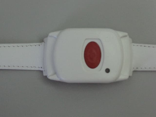
GSAWPK250
Jun 03, 2007PANIC WATCH
Equipment Class
DSC - Part 15 Security/Remote Control Transmitter
GSA5-RLE00125B
May 28, 2007LF Exciter
Equipment Class
DCD - Part 15 Low Power Transmitter Below 1705 kHz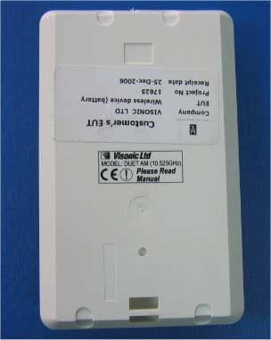
GSADUETAM
May 16, 2007Dual-Technology Microwave/PIR Intrusion Detector
Equipment Class
FDS - Part 15 Field Disturbance Sensor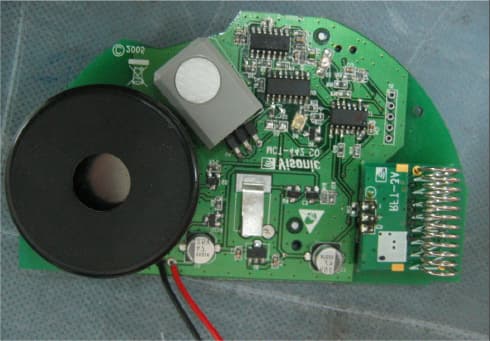
GSAMCT442
May 01, 2007Supervised Indoor Wireless CO Gas Detector
Equipment Class
DSC - Part 15 Security/Remote Control Transmitter