GTC025010PC-502.2
Honeywell International Inc.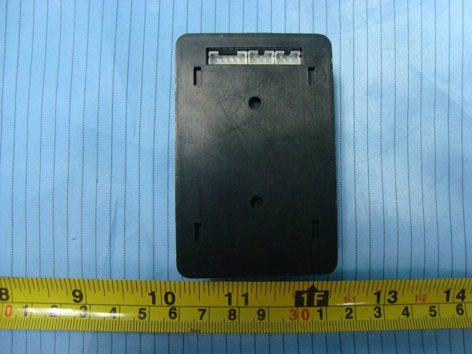
Click to zoom
Application Details
- Equipment Class
- DTS - Digital Transmission System
- Date of Grant
- Dec 29, 2009
- Application Purpose
- Original Equipment
- Date of Application
- Dec 29, 2009
- Equipment Note
- PC-502.2
- Frequency Range
- 2405.00000000 - 2475.00000000
- Company
- Honeywell International Inc.
- Country
- United States
Documents & Files
Document Text
Text extracted from the exhibit documents filed with the FCC. Open a document above to read the original.
Users Manual
INNCOMȱPCȬ502.2ȱDatasheetȱ Overviewȱ The INNCOM PC-502.2 wall mounted module can be used to expand the range of a Layer-2 RF network or provide the protocol gateway from INNCOM S5-bus to Layer-2 RF protocol. In the Layer-2.2 802.15.4 Zigbee 2006 mesh network, the PC-502.2 is designed to patch areas within the network where signal strength is lost due to distance limitations or interference. It also serves to create multiple pathways, increasing the redundancy of the mesh communications to ensure maximum network reliability. Featuresȱ xSmall wall mountable form factor x2.4Ghz IEEE 802.15.4 compliant RF transceiver (CC2430 radio core) xMedium and long range variants available xIndustrial temperature ratings 0-65 degrees C xFCC Part 15b listed Specificationȱ ParameterȱPCȬ502.2ȱ RF Data Rate 250kbps Antenna Type SMT Indoor Range100ft Outdoor/ RF line-of-sight range 1000ft+ Transmit Power 10mW (+18dBm) Receive Sensitivity -94.6dBm Frequency Band 2.405-2.475GHz Encryption AES-128 Protocol 802.15.4 Frequency Channels 15 Input Voltage 12VDC Current Consumption 100mA (Peak) Operating Ambient Temperature 40 ° C LED /Switch Reset indication, blinks when unit is connected to an RF network. Rapid blink during binding association. Figure 1 PC-502.2 10dBm 0-40,0-95%RH INNCOM PC-502.2 Datasheet Page | 2 Ranges are determined by performing an RF link quality test using e528.3G thermostats as the transmitter and the PC-502.2 as the receiver. The maximum distance threshold is based on a 95% overall link quality. Outdoor ranges were conducted in a low noise, free air environment. Indoor ranges are for reference. Indoor ranges are affected by the ambient environmental noise floor and building construction materials. NetworkȱTopologyȱ Figure 2 PC-502 Layer-2 Topology In this application, the PC-502.2 in participation with the e529.RF provides the Layer-1 to Layer-2 RF Bridge where both wireless in-room and wireless back-end networking are required. The PC- 502.2 can also patch areas within the Layer-2 network where signal strength is lost due to distance limitations or interference. INNCOM PC-502.2 Datasheet Page | 3 Commissioningȱ The PC-502.2 must be bound to the controlling device (e.g., the E529.RF in Figure 2 above) to receive configuration information. On the E529.RF in service mode xOpen the run menu and press Off/Auto xSet the value to 3 and press Display xWhen Display is pressed, the e529.RF sends Layer-2 configurations to the PC-502.2. (This function does not offer any feedback on the screen so it is recommended that the Display button be pressed 3 or 4 times to ensure configuration.) Safety/Regulatoryȱ ParameterȱConditionȱStatusȱ FCC Part 15b 02-9994 is FCC listed. 02-9894, and 02-9927 FCC listings are pending. PCȬ502.2ȱDimensionsȱ ȱ HeaderȱandȱConnectionsȱ H3ȱ(InȱSystemȱProgramming)ȱ PinȱFunctionȱTypeȱMinȱMaxȱ 1-8 Programming--- H4ȱ/ȱH5ȱ(S5ȬbusȱIn/Out)ȱ PinȱFunctionȱTypeȱMinȱMaxȱ 1-GND Common--- 2-12VDC Input voltage In11.75 12.25 INNCOM PC-502.2 Datasheet Page | 4 3-S5-bus Multi-drop In/Out- H6ȱ(SystemȬ5)ȱ PinȱFunctionȱTypeȱMinȱMaxȱ 1-GND Common--- 2-12VDC Input voltage In11.75 12.25 3-S5-bus Multi-drop In/Out- 4–InOut1 TTL In/Out- 5-InOut2 TTL In/Out- 3-pin to 3-pin harness for 12VDC and S5bus connection OrderingȱInformationȱ PartȱNumberȱOPNȱDescriptionȱ 01-5010.2 PC-502.2 PC-502 with 02-9894 20db Radio DocumentȱRevisionȱHistoryȱ RevisionȱDateȱIssuedȱȱReasonȱ 0.127-Mar-2009 FCC for PC-502 0.231-Mar-2009 Edited for content and format 1.007-Apr-2009 Released Warning Any Changes or modifications not expressly approved by the party responsible for compliance could void the user's authority to operate the equipment. This device complies with part 15 of the FCC Rules. Operation is subject to the following two conditions: (1) This device may not cause harmful interference, and (2) this device must accept any interference received, including interference that may cause undesired operation. IMPORTANT NOTE: FCC Radiation Exposure Statement: This equipment complies with FCC radiation exposure limits set forth for an uncontrolled environment .This equipment should be installed and operated with minimum distance 20 cm between the radiator& your body Note: This equipment has been tested and found to comply with the limits for a Class B digital device, pursuant to part 15 of the FCC Rules. These limits are designed to provide reasonable protection against harmful interference in a residential installation. This equipment generates, uses and can radiate radio frequency energy and, if not installed and used in accordance with the instructions, may cause harmful interference to radio communications. However, there is no guarantee that interference will not occur in a particular installation. If this equipment does cause harmful interference to radio or television reception, which can be determined by turning the equipment off and on, the user is encouraged to try to correct the interference by one or more of the following measures: —Reorient or relocate the receiving antenna. —Increase the separation between the equipment and receiver. —Connect the equipment into an outlet on a circuit different from that to which the receiver is connected. —Consult the dealer or an experienced radio/TV technician for help.
External Photos
EXHIBIT B - EUT EXTERNAL PHOTOGRAPHS EUT - Front View EUT - Rear View
ID Label/Location Info
EXHIBIT A - FCC ID LABELING AND LOCATION FCC ID Label FCC ID Label Location The label shown shall be permanently affixed at a conspicuous location on the device and be readily visible to the user at the time purchase (Labeling requirements per 2.925) Label here
Internal Photos
EXHIBIT C - EUT INTERNAL PHOTOGRAPHS EUT – Cover off View -1 EUT – Cover off View -2 EUT - Board View EUT – Radio Module Board Top View Antenna EUT – Radio Module Board Bottom View EUT – Logic Board Top View EUT – Logic Board Bottom View EUT – Power Supply Board Top View EUT – Power Supply Board Bottom View
RF Exposure Info
INNCOM International, Inc FCC ID: GTC025010 Report No.: RSZ09112001 Page 9 of 36 FCC Part15.247 Test Report FCC §15.247 (i) & §1.1307 (b) (1) & §2.1091- MAXIMUM PERMISSIBLE EXPOSURE (MPE) Standard Applicable According to subpart 15.247 (i) and subpart 1.1307 (b)(1), 2.1091 systems operating under the provisions of this section shall be operated in a manner that ensures the public is not exposed to RF energy level in excess of the communication guidelines. Limits for General Population/Uncontrolled Exposure Limits for General Population/Uncontrolled Exposure Frequency Range (MHz) Electric Field Strength (V/m) Magnetic Field Strength (A/m) Power Density (mw/cm 2 ) Averaging Time (Minutes) 0.3-1.34 614 1.63 *(100) 30 1.34-30 824/f 2.19/f *(180/f 2 ) 30 30-300 27.5 0.073 0.2 30 300-1500 / / f/1500 30 1500-100,000 / / 1.0 30 f = frequency in MHz * = Plane-wave equivalent power density Test Data Predication of MPE limit at a given distance S = PG/4πR² Where: S = power density (in appropriate units, e.g. mW/cm 2 ) P = power input to the antenna (in appropriate units, e.g., mW). G = power gain of the antenna in the direction of interest relative to an isotropic radiator, the power gain factor, is normally numeric gain. R = distance to the center of radiation of the antenna (appropriate units, e.g., cm) Maximum peak output power at antenna input terminal: 8.38 (dBm) Maximum peak output power at antenna input terminal: 6.89 (mW) Prediction distance: >20 (cm) Predication frequency: 2475 (MHz) Antenna Gain (typical): 1.0 (dBi) Maximum Antenna Gain: 1.26 (numeric) The worst case is power density at predication frequency at 20 cm: 0.0017 (mW/cm 2 ) MPE limit for general population exposure at prediction frequency: 1.0 (mW/cm 2 ) Result: The predicted power density level at 20 cm is 0.0017 mw/cm 2 , which is below the uncontrolled exposure limit of 1.0 mw/cm 2 , The EUT is used at least 20 cm away from user’s body. It is determined as mobile equipment and complies with the MPE limit.
Test Report
Note: This test report is prepared for the customer shown above and for the device described herein. It may not be duplicated or used in part without prior written consent from Bay Area Compliance Laboratories Corp. This report must not be used by the customer to claim product certification, approval, or endorsement by NVLAP*, NIST, or any agency of the Federal Government. * This report may contain data that are not covered by the NVLAP accreditation and are marked with an asterisk “*” (Rev.2) FCC PART 15.247 MEASUREMENT AND TEST REPORT For INNCOM International, Inc 277 West Main Street Niantic, CT 06357, USA FCC ID: GTC025010 Report Type: Original Report Product Type: PC-502.2 Test Engineer: Cookies Bu Report Number: RSZ09112001 Report Date: 2009-12-30 Reviewed By: Merry Zhao EMC Engineer Prepared By: Bay Area Compliance Laboratories Corp. (Shenzhen) 6/F, the 3rd Phase of WanLi Industrial Building, ShiHua Road, FuTian Free Trade Zone Shenzhen, Guangdong, China Tel: +86-755-33320018 Fax: +86-755-33320008 INNCOM International, Inc FCC ID: GTC025010 Report No.: RSZ09112001 Page 2 of 36 FCC Part15.247 Test Report TABLE OF CONTENTS GENERAL INFORMATION.......................................................................................................................................4 PRODUCT DESCRIPTION FOR EQUIPMENT UNDER TEST (EUT) .....................................................................................4 OBJECTIVE...................................................................................................................................................................4 RELATED SUBMITTAL(S)/GRANT(S).............................................................................................................................4 TEST METHODOLOGY..................................................................................................................................................4 TEST FACILITY.............................................................................................................................................................5 SYSTEM TEST CONFIGURATION ..........................................................................................................................6 DESCRIPTION OF TEST CONFIGURATION......................................................................................................................6 EUT EXERCISE SOFTWARE..........................................................................................................................................6 EQUIPMENT MODIFICATIONS.......................................................................................................................................6 LOCAL SUPPORT EQUIPMENT LIST AND DETAILS........................................................................................................6 EXTERNAL I/O CABLE..................................................................................................................................................6 CONFIGURATION OF TEST SETUP.................................................................................................................................7 BLOCK DIAGRAM OF TEST SETUP................................................................................................................................7 SUMMARY OF TEST RESULTS...............................................................................................................................8 FCC §15.247 (i) & §1.1307 (b) (1) & §2.1091- MAXIMUM PERMISSIBLE EXPOSURE (MPE)..............................9 STANDARD APPLICABLE..............................................................................................................................................9 TEST DATA..................................................................................................................................................................9 FCC §15.203 - ANTENNA REQUIREMENT...........................................................................................................10 STANDARD APPLICABLE............................................................................................................................................10 ANTENNA CONNECTOR CONSTRUCTION....................................................................................................................10 FCC §15.207 (a) - CONDUCTED EMISSIONS .......................................................................................................11 APPLICABLE STANDARD............................................................................................................................................11 MEASUREMENT UNCERTAINTY..................................................................................................................................11 EUT SETUP................................................................................................................................................................11 EMI TEST RECEIVER SETUP.......................................................................................................................................12 TEST EQUIPMENT LIST AND DETAILS.........................................................................................................................12 TEST PROCEDURE......................................................................................................................................................12 TEST RESULTS SUMMARY..........................................................................................................................................12 TEST DATA................................................................................................................................................................12 FCC §15.209, §15.205 & §15.247(d) - SPURIOUS EMISSIONS.............................................................................15 APPLIC…
Text truncated - open the document above for the full version.
Test Setup Photos
EXHIBIT D - TEST SETUP PHOTOGRAPHS Conducted Emissions - Front View Conducted Emissions - Side View Below 1 GHz: Spurious Radiated Emissions - Front View Below 1 GHz: Spurious Radiated Emissions - Rear View Above 1 GHz: Spurious Radiated Emissions - Front View Above 1 GHz: Spurious Radiated Emissions - Rear View
Contact Information
Applicant
Jeanne Enaux(Sr. Quality Engineering Manager)
Test Firm
Bay Area Compliance Laboratory Corp. (Shenzhen)John Chan
Technical Specifications
| # | Rule Parts | Frequency Range | Power Output |
|---|---|---|---|
| 1 | 15C | 2.40 GHz - 2.48 GHz | 6.90 mW |
Other Applications from Honeywell International Inc.
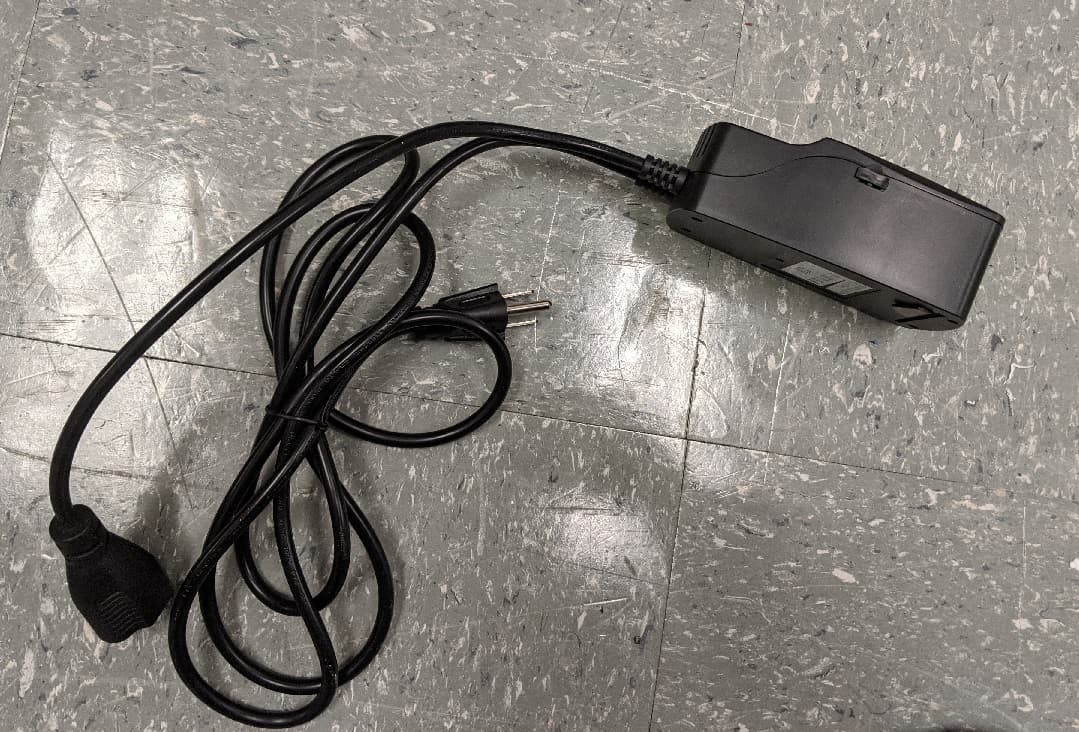
GTC-201705X
Mar 22, 2021L510 Lamp Controller
Equipment Class
DTS - Digital Transmission System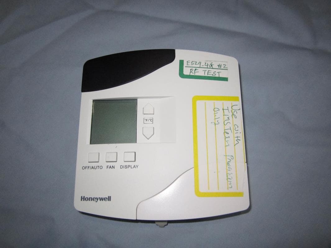
GTC202153TXR
Aug 27, 2014Battery Powered Thermostat
Equipment Class
DXX - Part 15 Low Power Communication Device Transmitter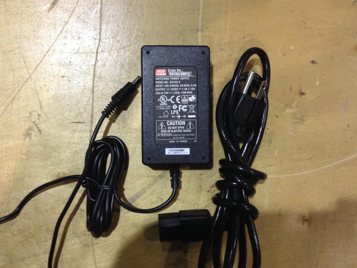
GTC201104TXR
Aug 26, 2014B578 Ethernet to RF Protocol Converter
Equipment Class
DXX - Part 15 Low Power Communication Device Transmitter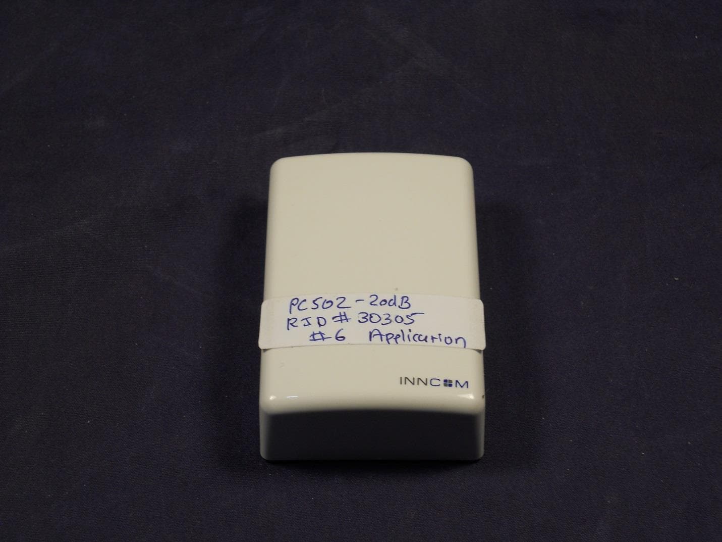
GTC202125TXR
Aug 17, 2014Wireless Repeater Module
Equipment Class
DTS - Digital Transmission System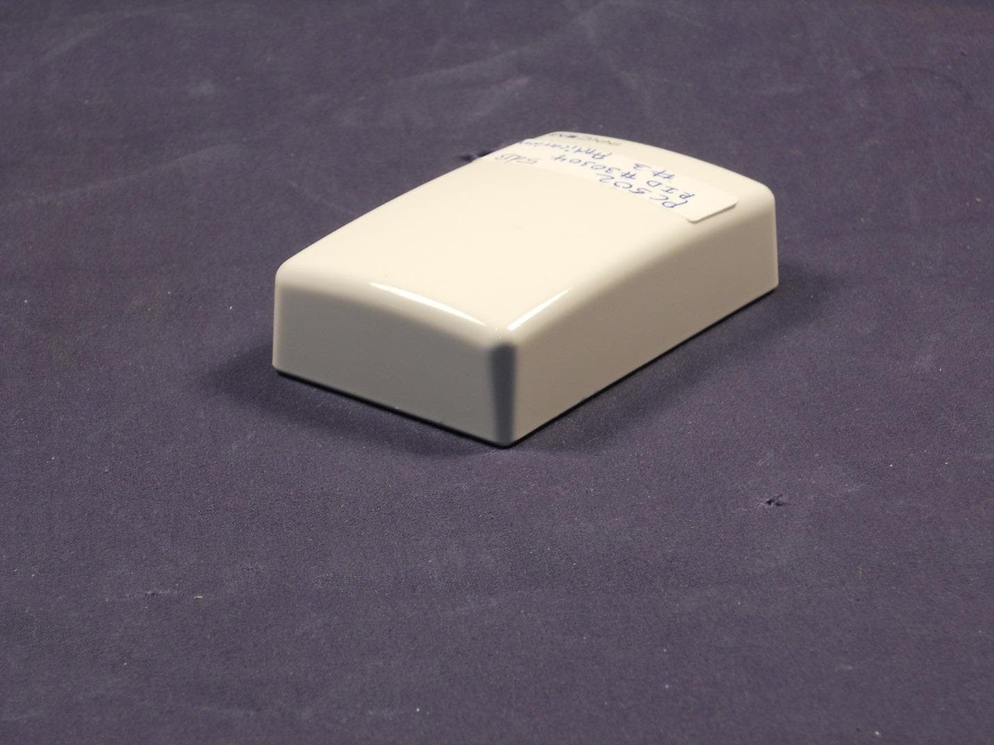
GTC202124TXR
Sep 18, 2013Repeater
Equipment Class
DXX - Part 15 Low Power Communication Device Transmitter