GTC027060TXRHousehold Amenities Control System
Honeywell International Inc.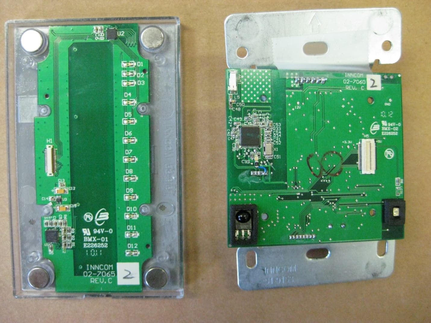
Click to zoom
Application Details
- Equipment Class
- DSS - Part 15 Spread Spectrum Transmitter
- Date of Grant
- Aug 24, 2010
- Application Purpose
- Original Equipment
- Date of Application
- Aug 24, 2010
- Equipment Note
- Household Amenities Control System
- Frequency Range
- 2405.00000000 - 2480.00000000
- Company
- Honeywell International Inc.
- Country
- United States
Documents & Files
Document Text
Text extracted from the exhibit documents filed with the FCC. Open a document above to read the original.
Users Manual
Global Leader in Integrated Room Automation Systems MODEVA Technical Reference Manual Disclaimer This document contains information that is the proprietary and confidential property of INNCOM International Inc. By acceptance hereof, each recipient agrees to use the information contained herein only for the purpose anticipated by INNCOM, and not to disclose to others, copy or reproduce, any part hereof without the written consent of INNCOM. The recipient agrees to return this document to INNCOM immediately upon request. Content 1 MODEVA Product Overview ........................................................................................ 2 2 MODEVA System Block Diagram ................................................................................. 2 3 Touch User Interface ................................................................................................ 3 4 MODEVA Logic Board ................................................................................................ 4 4.1 RF capability ........................................................................................................... 5 4.2 S5-bus ................................................................................................................... 5 4.3 IR Tx and Rx ........................................................................................................... 5 5 Load Assembly ........................................................................................................ 5 5.1 Categories of Load Assembly Load Switching ................................................................ 5 5.2 Load Assembly Dimming ........................................................................................... 6 5.3 Air-Gap Switch ........................................................................................................ 7 5.4 Overload Protection .................................................................................................. 7 5.5 Load Assembly Parallel Power Supplies ........................................................................ 8 6 MODEVA System Technical Specification ...................................................................... 8 6.1 MODEVA/Load Assembly Current Consumption Characteristics ...................................... 10 7 Load Specifications ................................................................................................. 10 7.1 Single gang installation ........................................................................................... 10 7.2 Multigang Installation ............................................................................................. 11 8 Multigang Installation Derating Chart ........................................................................ 11 8.1 Actuator Ratings .................................................................................................... 11 9 Standard Wiring ..................................................................................................... 12 10 MODEVA User Interface Assembly Ordering Information .............................................. 13 11 MODEVA Load Assembly Ordering Information ........................................................... 15 11.1 Load Assembly Ordering Information ........................................................................ 15 12 Document Information and Revision History ............................................................... 16 M O D E V A R e f e r e n c e M a n u a l P a g e 2 o f 16 1 MODEVA Product Overview The MODEVA™ system, an elegantly designed, easy to use lighting, drapes, and amenities control system, provides an unrivaled guestroom management experience. The MODEVA system allows guest control of multiple loads from many locations. MODEVA (comprising a logic board and user interface), in combination with the Load Assembly infrastructure (see below), consists of user interfaces, low voltage interfaces, wired and wireless communications, dimmers, and switches designed to operate within INNCOM’s Integrated Room Automation System (IRAS). The MODEVA system brings all guestroom control features into a sleekly designed unit housed in either a capacitive glass or a more traditional keypad user interface. The MODEVA system was designed by the engineers at INNCOM International Inc., who pioneered Energy Management Systems in the hotel industry long before “green” was a marketing concept. INNCOM is again blazing a trail for enhanced guestroom controls with the MODEVA and Load Assembly system. The MODEVA system brings an unmatched level of design flexibility by utilizing a “system in a box” approach. Mixing a variety of individual components and actuators, the MODEVA system provides endless guestroom control features and options that interoperate seamlessly with INNCOM’s e4 Smart Digital Thermostat for an unparalleled energy management and lighting control platform. With the fully configurable user interface and logic board, which allows the hotelier and the INNCOM design team to create a unique look and feel while customizing functionality, the MODEVA system can meet nearly any design requirement conceived for the hotel guestroom. MODEVA itself contains all of the hardware components (including logic operations, radio communications, and user interface functionality) necessary to operate as a low voltage controls interface within a thin (8mm thick) assembly that rests outside of the wall box cavity. This brings an incredible advantage to MODEVA by allowing it to be decoupled safely from the line power switching and dimming performed by the system’s Load Assembly actuators. Since the MODEVA user interface is 12VDC powered and equipped with wired S5-bus communications and a 2.4 GHz RF radio, it can be used as a standalone, low voltage controls interface for load center style applications. This also frees the MODEVA from the mechanical confines of gang box dimensions. Coupled…
Text truncated - open the document above for the full version.
Cover Letter(s)
28 www.johansontechnology.comwww.johansontechnology.com INTEGRATED PASSIVE COMPONENTS BALUN BALUN DIPLEXER BP FILTERBP FILTERBP FILTER LP FILTERCOUPLER ANTENNA DIVIDER DEMOD. MOD.PA LNA VCO KEY FEATURES • Custom Solutions • LTCC Based Designs • Low Insertion Loss • Miniature Size / Low Profile • Temperature Stable • Surface Mount • RoHS Compliant, Standard, Use No Suffix SUPPORTED APPLICATION BANDS • Wireless LAN, Bluetooth, Home RF • 2.4 GHz & 5.5 GHz ISM Band • GPS • GSM/EDGE/GPRS/DCS/PCS/WCDMA • Zigbee • UNII • WiMAX 802.16 • MiMo • UWB Johanson Technology has developed a line of small, highly reliable RF ceramic components manufactured with a proprietary LTCC (low temperature co-fired ceramic) process. These components operate over several bands from 900MHz to 6 GHz covering Cellular, DECT, WLAN, Bluetooth, 802.11 (a,b and g) and GPS applications. In addition to the array of listed components we can support custom solutions for high volume applications with design flexibility and short development times. Contact us today with your specific technical requirements. 29 www.johansontechnology.com Detailed specifications and performance curves for the RF Ceramic Component line are located on our website. CERAMIC CHIP ANTENNAS Part Frequency Peak Gain Ave. Gain Return Case Number (MHz) Loss Size 0920AT50A080 880 - 960 -0.7 dBi typ (XZ-V) -2.6 dBi typ (XZ-V) 8.5 dB min. Case 50 1575AT43A40 1555 - 1595 - 1.5 dBi typ (XZ-V) -2.5 dBi typ (XZ-V) 9.5 dB min. Case 43-1 1575AT47A40_ 1555 - 1595 -1.0 dBi typ (XZ-V) -3.0 dBi typ (XZ-V) 9.5 dB min. Case 47-1 2450AT18A100 2400 - 2500 0.5 dBi typ (XZ-V) -0.5 dBi typ (XZ-V) 9.5 dB min. Case 18-4 2450AT42A100 2400 - 2500 0 dBi typ (XZ-V) -1 dBi typ (XZ-V) 9.5 dB min. Case 42-1 2450AT42B100 2400 - 2500 0 dBi typ (XZ-V) -1.5 dBi typ (XZ-V) 9.5 dB min. Case 42-2 2450AT43A100 2400 - 2500 2.0 dBi typ (XZ-V) 0.5 dBi typ (XZ-V) 9.5 dB min. Case 43-1 2450AT43B100 2400 - 2500 1.0 dBi typ (XZ-V) -0.5 dBi typ (XZ-V) 9.5 dB min. Case 43-2 2450AT44A100_ 2400 - 2500 1.3 dBi typ (XZ-V) 0 dBi typ (XZ-V) 9.5 dB min. Case 44-1 2450AT45A100_ 2400 - 2500 3.0 dBi typ (XZ-V) 1.0 dBi typ (XZ-V) 9.5 dB min. Case 45-1 2450AD46A5400 LB: 2400 - 2500 1.0 dBi typ (XZ-V) -1.5 dBi typ (YZ-V) 8.5 dB min. Case 46-1 (Dual Band) HB: 4900 - 5900 -2.5 dBi typ (XZ-V) -2.5 dBi typ (YZ-V) 8.5 dB min. 2500AT52M3555 WiMax (Tri-Band) See spec sheet See spec sheet 9.5 dB min. TBD 5250AT43A200_ 5150 - 5350 3.6 dBi typ (XZ-V) -2.3 dBi typ (XZ-V) 9.5 dB min. Case 43-1 5400AT18A1000 4900 - 5900 2.0 dBi typ. (XZ-V) -2.5 dBi typ (XZ-V) 9.5 dB min. Case 18-4 5775AT43A100_ 5725 - 5825 3.9 dBi typ (XZ-V) -1.5 dBi typ (XZ-V) 9.5 dB min. Case 43-1 Case 46-1 .335 In. (8.5 mm) 0.63 In. (1.6 mm) .047 In. (1.2 mm) (Top) (Side) (Bottom) Case 45-1 .374 In. (9.5 mm) .079 In. (2.0 mm) .047 In. (1.2 mm) (Top) (Bottom) (End) Case 47-1 .394 In. (10.0 mm) .118 In. (3.0 mm) .030 In. (0.77 mm) (Top) (Bottom) (End) Case 44-1 .299 In. (7.6mm) .138 In. (3.5 mm) .051 In. (1.3 mm) (Top)(End) Case 43-1 .276 In . (7.0 mm) .079 In . (2.0 mm) .047 In . (1.2 mm) (T op) ( Bottom) ( End) Case 18-4 .063 In. (1.6 mm) .126 In. (3.2 mm) .051 In. (1.3 mm) Case 50 .433 In . (11.0mm) .201 In. (5.1 mm) .059 In. (1.5 mm) (Top)(End) .079 In. (2.0 mm) (Top) .197 In . mm)(5.0 (Side) .043 In . mm)(1.1 Case 42-1 .079 In. (2.0 mm) (Top) .197 In . mm)(5.0 (Bottom) .079 In . mm)(2.0 .079 In . (2.0 mm) (End) Case 42-2 .276 In. (7.0 mm) .079 In. (2.0 mm) .079 In . (2.0 mm) (Top) (Bottom) (End) Case 43-2 30 www.johansontechnology.com BAND-PASS FILTERS: 2.45 GHZ Part Frequency Insertion Return Ripple Case Number (MHz) Loss (max) Attenuation (min) Loss (min) (typical) Size 2450BP14C0100 2450 ± 50 2.0 dB TBD 9.5 dB - Case 14-TBD 2450BP15B100 2450 ± 50 2.2 dB 25 dB @ 1200-1300 MHz 9.5 dB - Case 15-3 10 dB @ 2000 MHz 12 dB @ 3000 MHz 30 dB @ 3600-3800 MHz 34 dB @ 4800-5000 MHz 2450BP15D100 2450 ± 50 2.6 dB (Prelim.) 30 dB @ 880 - 1990 MHz (Prelim.) 9.5 dB - Case 15-1F 20 dB @ 2110 - 2170 MHz (Prelim.) 30 dB @ 4800 - 5000 MHz (Prelim.) 20 dB @ 7200 - 7500 MHz (Prelim.) 2450BP15C100 2450 ± 50 2.2 dB (Prelim.) 30 dB @ 1200-1300 MHz (Prelim.) 9.5 dB - Case 15-3B 15 dB @ 2000 MHz (Prelim.) 25 dB @ 3000 MHz (Prelim.) 20 dB @ 3600-3800 MHz (Prelim.) 20 dB @ 4800-5000 MHz (Prelim.) 2450BP15E0100 2450 ± 50 1.5 dB TBD 9.5 dB - Case 15-3C 2450BP18C100A 2450 ± 50 2.5 dB 40 dB @ 1.2-1.8GHz 9.5 dB 0.7 dB Case 18-1 25 dB @ 2.1GHz 35 dB @ 4.8-5.0GHz 25 dB @ 7.2-7.5 GHz 2450BP18C100B 2450 ± 50 2.0 dB 30 dB @ 1.75 GHz 9.5 dB 0.7 dB Case 18-2 25 dB @ 2.10 GHz 22 dB @ 4.8-5.0 GHz 2450BP18C100C 2450 ± 50 2.5 dB 30 dB @ 1.2-1.8 GHz 9.5 dB 0.7 dB Case 18-3A 25 dB @ 2.1 GHz 35 dB @ 4.8-5.0 GHz 2450BP18C100D 2450 ± 50 2.0 dB 40 dB @ 900-928 MHz 9.5 dB 0.7 dB Case 18-3B 30 dB @ 1.2-1.8 GHz 25 dB @ 2.1 GHz 35 dB @ 4.8-5.0 GHz 30 dB @ 7.2-7.5 GHz 2450BP18D100A 2450 ± 50 TBD dB TBD TBD dB TBD dB Case 18-3C 2450BP39C100A 2450 ± 50 2.5 dB 42 dB @ 1.71-1.99 GHz 9.5 dB 0.7 dB Case 39-1 30 dB @ 2.1 GHz 30 dB @ 4.8-5.0 GHz 2450BP39C100B 2450 ± 50 1.8 dB 30 dB @ 1.71-1.78 GHz 9.5 dB 0.7 dB Case 39-1 25 dB @ 1.85-1.91 GHz 25 dB @ 4.8-5.0 GHz 2450BP39C100C 2450 ± 50 1.5 dB 30 dB @ 800-915 MHz 9.5 dB - Case 39-1 30 dB @ 1710-1785 MHz 25 dB @ 1850-1910 MHz 25 dB @ 4800-5000 MHz 15 dB @ 7200-7500 MHz 2450BP39D100B 2450 ± 50 2.5 dB 35 dB @ 880 - 915 MHz 9.5 dB - Case 39-1 18 dB @ 1710 - 1990 MHz 12 dB @ 2100 MHz 35 dB @ 3200 MHz 22 dB @ 4800 - 5000 MHz 22 dB @ 7200 - 7500 MHz Basic case size drawings for above part numbers are located on page 37. Detailed specifications and performance curves for the RF Ceramic Component line are located on our website. 31 www.johansontechnology.com Basic case size drawings for above part numbers are located on page 37. Detailed specifications and performance curves for the RF Ceramic Component line are located on our website. BAND-PASS FILTERS: 5.5 GHZ Part Frequency Insertion Return Case Number (MHz) Loss (max) Attenuation (min) Loss (min) Ripple Size 5450BP15T600…
Text truncated - open the document above for the full version.
External Photos
EXTERNAL PHOTOS Company Name INNCOM International, Inc. Model # 02‐7060 FCC ID # GTC02060TXR Page 1 of 3 Front View of EUT EXTERNAL PHOTOS Company Name INNCOM International, Inc. Model # 02‐7060 FCC ID # GTC02060TXR Page 2 of 3 Back View of EUT EXTERNAL PHOTOS Company Name INNCOM International, Inc. Model # 02‐7060 FCC ID # GTC02060TXR Page 3 of 3 Back Cover of EUT Opened
ID Label/Location Info
INNCOM International Inc. Model: Single Gang Modeva Capacitive Touch and Logic Assembly www.inncom.com 92-7060 Assembly Part Number: 03-7060. This device contains FCCID GTC027060TXR. GHS1 R1 WH 65mm 16mm INNCOM International Inc. Model: Single Gang Modeva Capacitive Touch and Logic Assembly www.inncom.com 92-7060 Assembly Part Number: 03-7060. This device contains FCCID GTC027060TXR. GHS1 R1 WH
Internal Photos
INTERNAL PHOTOS Company Name INNCOM International, Inc. Model # 02‐7060 FCC ID # GTC02060TXR Page 1 of 5 Front Side of RF Board INTERNAL PHOTOS Company Name INNCOM International, Inc. Model # 02‐7060 FCC ID # GTC02060TXR Page 2 of 5 Backside of RF Board INTERNAL PHOTOS Company Name INNCOM International, Inc. Model # 02‐7060 FCC ID # GTC02060TXR Page 3 of 5 Close‐up of RF Section and Antenna INTERNAL PHOTOS Company Name INNCOM International, Inc. Model # 02‐7060 FCC ID # GTC02060TXR Page 4 of 5 Inside View of RF Board INTERNAL PHOTOS Company Name INNCOM International, Inc. Model # 02‐7060 FCC ID # GTC02060TXR Page 5 of 5 Backside View of Open RF Board
RF Exposure Info
EXHIBIT 13. MPE CALCULATIONS The following MPE calculations are based on a ceramic chip antenna, with a measured ERP of 95.4 dBμV/m (at 3 meters) and conducted RF power of -0.1 dBm as presented to the antenna. The peak gain of this antenna, based on the data sheet is 1.0 dBi.
Test Report
W66 N220 Commerce Court ● Cedarburg, WI 53012 ● USA Phone: 262.375.4400 ● Fax: 262.375.4248 www.lsr.com TEST REPORT # 310138 LSR Job #: C-912 Compliance Testing of: INNCOM GS2 Test Date(s): May 18 th and 29 th , June 15 th and 24 th , July 6 th to 10 th 2010 Prepared For: INNCOM International 277 West Main Street Niantic, CT 6357 In accordance with: Federal Communications Commission (FCC) Part 15, Subpart C, Section 15.247 Industry Canada (IC) RSS 210 Annex 8 Digital Modulation Transmitters (DTS) Operating in the Frequency Band 2400 MHz – 2483.5 MHz This Test Report is issued under the Authority of: Signature: Date: 07.26.10 Test Report Reviewed by: Signature: Date: 07.26.10 Tested by: Khairul Aidi Zainal, Senior EMC Engineer Signature: Date: 07.21.10 This Test Report may not be reproduced, except in full, without written approval of LS Research, LLC. Prepared For:Inncom International EUT:GS2 LS Research, LLC Report #310138 Model #:02-7060 Template: DTS 10-22-09 LSR Job #:C-912 Serial #:Engineering Prototype Page 2 of 50 TABLE OF CONTENTS (page 1 of 2) EXHIBIT 1: INTRODUCTION 1.1 Scope 4 1.2 Normative References 4 1.3 LS Research, LLC Test Facility 5 1.4 Location of Testing 5 1.5 Test Equipment Utilized 5 EXHIBIT 2: PERFORMANCE ASSESSMENT 2.1 Client Information 6 2.2 Equipment Under Test (EUT) Information 6 2.3 Associated Antenna Description 6 2.4 EUT’s Technical Specifications 7 2.5 Product Description 8 EXHIBIT 3: EUT OPERATING CONDITIONS & CONFIGURATIONS DURING TESTS 3.1 Climate Test Conditions 9 3.2 Applicability & Summary of EMC Emission Test Results 9 3.3 Modifications Incorporated in the EUT for Compliance Purposes 9 3.4 Deviations & Exclusions from Test Specifications 9 EXHIBIT 4: DECLARATION OF CONFORMITY 10 EXHIBIT 5: RADIATED EMISSIONS TESTING 5.1 Test Setup 11 5.2 Test Procedure 11 5.3 Test Equipment Utilized 12 5.4 Test Results 12 5.5 Calculation of Radiated Emissions Limits 13 5.6 Radiated Emissions Test Data Chart 14 5.7 Test Setup Photo(s) – Radiated Emissions Test 17 5.8 Screen Captures – Radiated Emissions Test 18 EXHIBIT 6: CONDUCTED EMISSIONS TEST, AC POWER LINE 6.1 Test Setup 22 6.2 Test Procedure 22 6.3 Test Equipment Utilized 22 6.4 Test Results 22 6.5 FCC Limits of Conducted Emissions at the AC Mains Ports 23 6.6 Conducted Emissions Test Data Chart 24 6.7 Test Setup Photo(s) – Conducted Emissions Test 25 6.8 Screen Captures – Conducted Emissions Test 26 Prepared For:Inncom International EUT:GS2 LS Research, LLC Report #310138 Model #:02-7060 Template: DTS 10-22-09 LSR Job #:C-912 Serial #:Engineering Prototype Page 3 of 50 TABLE OF CONTENTS (Page 2 of 2) EXHIBIT 7: OCCUPIED BANDWIDTH 7.1 Limits 27 7.2 Method of Measurements 27 7.3 Test Data 27 7.4 Screen Captures – Occupied Bandwidth 28 EXHIBIT 8: BAND-EDGE MEASUREMENTS 8.1 Method of Measurements 32 EXHIBIT 9: POWER OUTPUT (CONDUCTED): 15.247(b) 9.1 Method of Measurements 34 9.2 Test Data 34 9.3 Screen Captures – Power Output (Conducted) 35 EXHIBIT 10: POWER SPECTRAL DENSITY: 15.247(e) 10.1 Limits 37 10.2 Test Data 37 10.3 Screen Captures – Power Spectral Density 38 EXHIBIT 11: CONDUCTED SPURIOUS EMISSIONS: 15.247(d) 11.1 Limits 40 11.2 Test Data 41 11.3 Screen Captures – Spurious Radiated Emissions 42 EXHIBIT 12: FREQUENCY & POWER STABILITY OVER VOLTAGE VARIATIONS 44 EXHIBIT 13: MPE CALCULATIONS 45 APPENDICES APPENDIX A: TEST EQUIPMENT LIST 46 APPENDIX B: TEST STANDARDS – RADIO 48 APPENDIX C: UNCERTAINTY STATEMENT 49 APPENDIX D: ANTENNA SPECIFICATIONS 50 Prepared For:Inncom International EUT:GS2 LS Research, LLC Report #310138 Model #:02-7060 Template: DTS 10-22-09 LSR Job #:C-912 Serial #:Engineering Prototype Page 4 of 50 EXHIBIT 1. INTRODUCTION 1.1 SCOPE References: FCC Part 15, Subpart C, Section 15.247 and 15.209 FCC Part 2, Section 2.1043 paragraph (b)1. RSS GEN and RSS 210 Annex 8 Title: FCC : Telecommunication – Code of Federal Regulations, CFR 47, Part 15. IC : Low-power License-exempt Radio-communication Devices (All Frequency Bands): Category I Equipment Purpose of Test: To gain FCC and IC Certification Authorization for Low- Power License-Exempt Transmitters. Test Procedures: Both conducted and radiated emissions measurements were conducted in accordance with American National Standards Institute ANSI C63.4 – American National Standard for Methods of Measurement of Radio-Noise Emissions from Low-Voltage Electrical and Electronic Equipment in the Range of 9 kHz to 40 GHz. Environmental Classification: • Commercial, Industrial or Business • Residential 1.2 NORMATIVE REFERENCES Publication Title 47 CFR, Parts 0-15 (FCC) Code of Federal Regulations - Telecommunications RSS 210 Annex 8 Low-power License-exempt Radio-communication Devices (All Frequency Bands): Category I Equipment ANSI C63.4 American National Standard for Methods of Measurement of Radio-Noise Emissions from Low-Voltage Electrical and Electronic Equipment in the Range of 9 kHz to 40 GHz. CISPR 16-1-1 Specification for radio disturbance and immunity measuring apparatus and methods. Part 1-1: Measuring Apparatus. CISPR 16-2-1 Specification for radio disturbance and immunity measuring apparatus and methods. Part 201: Conducted disturbance measurement. FCC ET Docket No. 99-231 Amendment to FCC Part 15 of the Commission’s Rules Regarding Spread Spectrum Devices. FCC Procedures Measurement of Digital Transmission Systems operating under Section 15.247. Prepared For:Inncom International EUT:GS2 LS Research, LLC Report #310138 Model #:02-7060 Template: DTS 10-22-09 LSR Job #:C-912 Serial #:Engineering Prototype Page 5 of 50 1.3 LS Research, LLC TEST FACILITY LS Research, LLC is accredited by A2LA (American Association for Laboratory Accreditation) to conform to ISO/IEC 17025, 2005 “General Requirements for the Competence of Calibration and Testing Laboratories”. LS Research, LLC’s scope of accreditation includes all test methods listed herein, unless otherwise noted. A copy of the accreditation may be accessed on our web site: www.lsr.com . Accredi…
Text truncated - open the document above for the full version.
Test Setup Photos
TEST SETUP PHOTOS Company Name INNCOM International, Inc. Model # 02‐7060 FCC ID # GTC02060TXR Page 1 of 2 Radiated Emissions Test Setup Photo TEST SETUP PHOTOS Company Name INNCOM International, Inc. Model # 02‐7060 FCC ID # GTC02060TXR Page 2 of 2 Conducted Emissions Test Setup Photo
Contact Information
Applicant
Jeanne Enaux(Sr. Quality Engineering Manager)
Technical Contact
InnComRyan Gardner
[email protected]860-739-4468
277 West Main Street · Niantic, Wisconsin · United States
Test Firm
LS Research, LLCRyan Urness
Technical Specifications
| # | Rule Parts | Frequency Range | Power Output |
|---|---|---|---|
| 1 | 15C | 2.40 GHz - 2.48 GHz | 1.00 mW |
Other Applications from Honeywell International Inc.
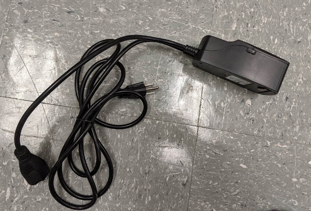
GTC-201705X
Mar 22, 2021L510 Lamp Controller
Equipment Class
DTS - Digital Transmission System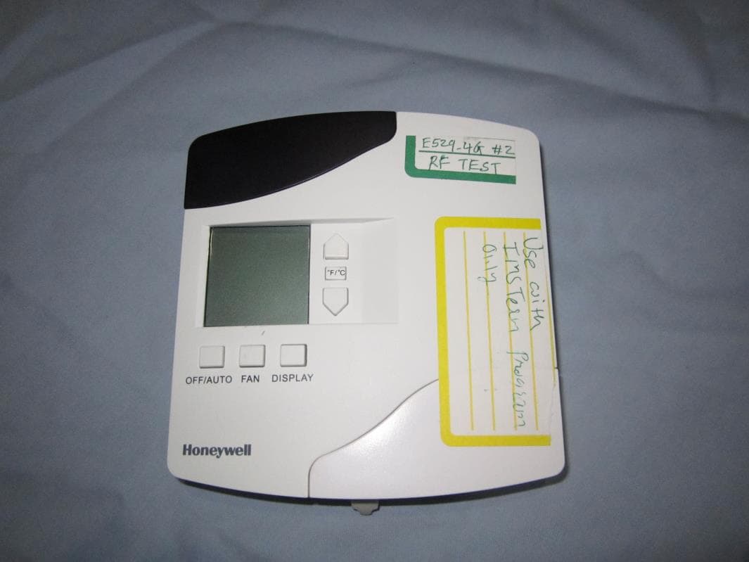
GTC202153TXR
Aug 27, 2014Battery Powered Thermostat
Equipment Class
DXX - Part 15 Low Power Communication Device Transmitter
GTC201104TXR
Aug 26, 2014B578 Ethernet to RF Protocol Converter
Equipment Class
DXX - Part 15 Low Power Communication Device Transmitter
GTC202125TXR
Aug 17, 2014Wireless Repeater Module
Equipment Class
DTS - Digital Transmission System
GTC202124TXR
Sep 18, 2013Repeater
Equipment Class
DXX - Part 15 Low Power Communication Device Transmitter