GTC029994TXRINNCOM TXR Radio Transceiver
Honeywell International Inc.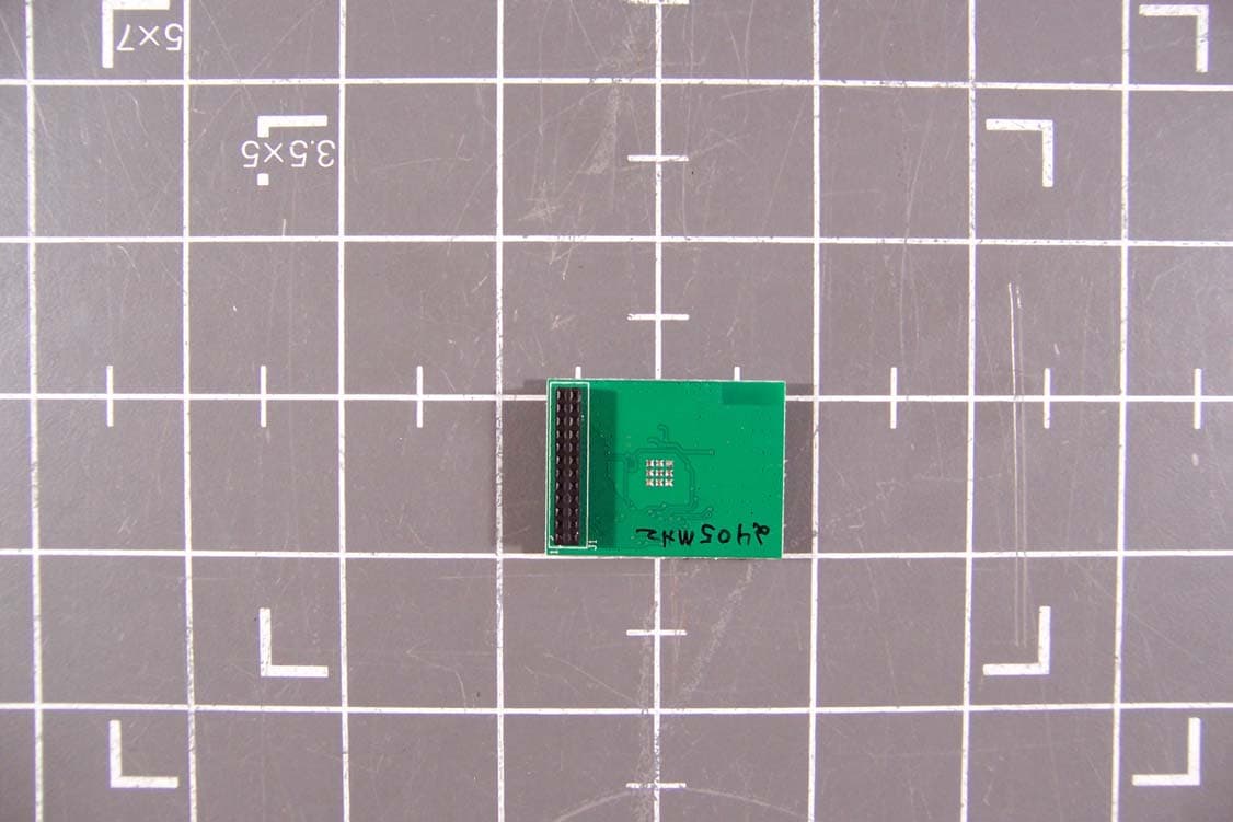
Click to zoom
Application Details
- Equipment Class
- DTS - Digital Transmission System
- Date of Grant
- Jan 25, 2010
- Application Purpose
- Original Equipment
- Date of Application
- Jan 20, 2010
- Equipment Note
- INNCOM TXR Radio Transceiver
- Frequency Range
- 2405.00000000 - 2480.00000000
- Company
- Honeywell International Inc.
- Country
- United States
Documents & Files
Document Text
Text extracted from the exhibit documents filed with the FCC. Open a document above to read the original.
Users Manual
INNCOM TXR RF Module Datasheet Overview The INNCOM TXR series of embedded RF radio modules provides INNCOM products with a common radio platform. The TXR RF radios are used in the point to point Layer-1 in-room network and in Layer-2 802.15.4 Zigbee 2006 mesh network topologies at 2.4 GHz. Features • Common footprint designed for use with a variety of host products • Multiple antenna options • 2.4Ghz IEEE 802.15.4 compliant RF transceiver (CC2430 radio core) • Low power and long range variants available • Industrial temperature ratings 0-65 C° • FCC Part 15C Table 1 INNCOM TXR Radio Specifications Performance 02‐9994 02‐9894 02‐9927 RF Data Rate 250kbps 250kbps 250kbps Antenna Type SMT u.FL male connector SMT Indoor Range 70ft 98ft 100ft Outdoor/ RF line-of-sight range 540ft 980ft+ 1000ft+ Transmit Power 1mW (+0dBm) 2mW (+2dBm) 10mW (+18dBm) Receive Sensitivity -94.6dBm -94dBi -94.6dBm Frequency Band 2.4Ghz 2.4Ghz 2.4Ghz Encryption AES-128 AES-128 AES-128 Protocol 802.15.4 802.15.4 802.15.4 Frequency Channels 11-26 11-26 11-26 Dimensions 28mm x 38mm 28mm x 38mm 28mm x 38mm Ranges are determined by performing an RF link quality test using two identical e528.3G thermostats containing radios as defined in tables 2 and 3. The maximum distance threshold is based on a 95% overall link quality. Outdoor ranges were conducted in a low noise, free air environment. Indoor ranges are for reference. Indoor ranges are impacted by the ambient environmental noise floor, and building construction materials. INNCOM TXR RF Module Datasheet Page | 2 Secondary Range Performance Data The following table describes the indoor and outdoor range when using un-like antenna combinations. Table 2 INNCOM TXR Radio Indoor Range Transmitter Receiver Receiver Receiver 02-9994 02-9894 02-9927 02-9994 70ft (21m) 73ft (22m) 98ft (30m) 02-9894 100ft (31m) 100ft (31m) 100ft (31m) 02-9927 90ft (27m) 100ft (31m) 98ft (30m) Table 3 INNCOM TXR Radio Outdoor Range Transmitter Receiver Receiver Receiver 02-9994 02-9894 02-9927 02-9994 540ft (165m) 570ft (174m) 654ft (199m) 02-9894 640ft (195m) 980ft+ (299m+) 768ft (234m) 02-9927 550ft (168m) 620ft (189m) 980ft+ (299m+) Table 4 INNCOM TXR Operating Conditions Parameter Min Max Unit Operating ambient temperature range -40 85 °C Operating supply voltage 2.0 3.6 V The supply pins to the radio must be driven by the 1.8VDC on-chip voltage regulator. Table 5 INNCOM TXR Safety / Regulatory Agency Approval Specification Status FCC 15.247 02-9994 Certified under FCC ID: GTC029994TXR FCC 15.247 02-9894 Certified under FCC ID: GTC029894TXR Only approved antennas can be used with this module. Additional antennas would require an application filing with the FCC in order to have them approved. Antennas which have either a higher gain or are of a different type may not be used, with this module, unless additional certification is obtained. All Final Products containing the INNCOM TXR 02-9994 must contain the following statements on their label: This device contains FCC ID: GTC029994TXR. This device complies with part 15 of the FCC Rules. Operation is subject to the following two conditions: (1) This device may not cause harmful interference, and (2) this device must accept any interference received, including interference that may cause undesired operation. The followings statements are required in the final product user manuals: This equipment has been tested and found to comply with the limits for a Class A digital device, pursuant to Part 15 of the FCC Rules. These limits are designed to provide reasonable protection against harmful interference when the equipment is operated in a commercial environment. This INNCOM TXR RF Module Datasheet Page | 3 equipment generates, uses, and can radiate radio frequency energy and, if not installed and used in accordance with the instruction manual, may cause harmful interference to radio communications. Operation of th is equipment in a residential area is likely to cause harmful interference in which case the user will be required to correct the interference at his own expense. All Final Products containing the INNCOM TXR 02-9894 should keep a safe distance of at least 20cm from all persons. The final product cannot be co located with any other antenna or transmitter. Modifications not expressly approved by INNCOM International Inc. could void the user’s authority to operate the equipment. Ordering Information Part Number Model Number Assembly 02-9994 TXR-154.1 0dB radio with SMT antenna 02-9927 TXR-154.x 0dB radio with 5”u.fl to rpsma harness / ½ wave dipole antenna 02-9894 TXR-154.2 20dB radio with SMT antenna Document Revision History Revision Date Issued Reason 0.1 20-Mar-2009 FCC Reports for 02-9894, 02-9927 0.2 24-Mar-2009 Revised for formatting and style 0.3 27-Mar-2009 Revised to update range performance data 1.0 07-Apr-2009 Released 1.1 23-Dec-2009 Updated to add FCC statements 1.2 07-Jan-2010 Added modifications warning 1.3 14-Jan-2010 Updated FCC statements
Cover Letter(s)
05/28/2009 Federal Communications Commission 7435 Oakland Mills Road Columbia, MD 21046 Gentlemen: This letter is to comply with Section 0.457( d)(2)(i) and Section 0.459 pertaining to confidential material. INNCOM International Inc. would like the following documents regarding this submission for FCC ID: GTC029994TXR to be kept confidential. 1. All Schematics 2. All Operational Descriptions 3. All Block Diagrams The above material contains trade secrets or technical data, which would customarily be guarded from competitors. We do not want these documents to be accessible to the general public. Ryan Gardner Director of New Product Development INNCOM International
Cover Letter(s)
8/10/2009 Federal Communications Commission 7435 Oakland Mills Road Columbia, MD 21046 Subject: Short-term confidentiality request regarding application for certification of FCC ID: GTC029994TXR Gentlemen: Pursuant to DA 04-1705 of the Commission's public notice, we request short-term confidential treatment for the following information until 180 days after the Grant Date of Equipment Authorization in order to ensure sensitive business information remains confidential until the actual marketing of the device: 1. Internal Photos The above material contains trade secrets or technical data that if other companies with in the same industry were able to view, it would remove the edge on the market that this product provides our company. Ryan Gardner Director of New Product Development INNCOM International
Cover Letter(s)
Non-Conformities FCC ID: GTC029994TXR (CKC CS Ref # E09-000111-FCC-01) The items listed below represent requests for information following review of this application for certification under United S tates (FCC) regulations. Further question may arise pending review of responses to these items. OK ID # Non-Conformity or Comment Subm itted Response Respondent / Date of Response X 1 The external photos exhibits ar e required. The internal photos have been placed in this field. Provided CKC 9/9/09 C X 2 The ID label provided incorrectly lists the requested FCC ID. The proper label format is “FCC ID: GTC029994TXR” Please provide an updated label. Updated label information provided. C X 3 The ID label provided includes the statement required by 15.19. Please note that this statement is not required to be a part of the module label, however is required on the exterior of the final product. The 15.19 statement may be removed from the module label if so desired. This item is informative, no response necessary. N/A N/A c X 4 Please note that the grantee code information must list the party responsible for compliance, incl uding the contact name. Please update your grantee information to include a contact name. Please note that the contact name is the person authorized to sign form 731 applications and confidentiality letters. This authority may be delegated or assigned as necessary however the delegation of authority must be provided in the form of a letter and attached as part of the application filing. This application cannot be approved until the Grantee code contact name is updated. Grantee code modified Ryan Gardner 11/3/09 c X 5 The confidentiality letter provided requests confidentiality for internal photos. This request can only be granted with direct FCC permission. Without further documentation and justification of the request, it is highly likely that the present request would be rejected. Please also note item 1; for modular approval, external photos remain required and must be provided (eg, they’re the same as the internal photos). External photos may not be held confidential for commercial products. Please either remove internal photos confidentiality or provide further justification for holding internal photos confidential (example: the equipment will be locked behind a door not accessible to the general public and the enclos ure requires the use of specialized Updated confidentiality letters provided. Ryan Gardner 9/8/09 tools to open the equipment; service is performed by factory trained personnel who have signed non-disclosure agreements or will be performed by Employees of INNCOM) c X 6 The FCC ID listed in the confidentiality letter is incorrect, see item 2. Updated confidentiality letters provided. Ryan Gardner 9/8/09 c X 7 The FCC ID listed in the temporar y confidentiality letter is incorrect, see item 2. Updated confidentiality letters provided. Ryan Gardner 9/8/09 c X 8 The Temporary confidentiality letter includes the confidential material. The letter itself must be held open for public inspection. If the materials requested for temporary confidentiality are the internal photos only, then list the specific category of exhibit as “all internal photos.” Please note that internal photos, external photos, users manual and test setup photos may be held temporarily confidential. If an item is listed under permanent confidentiality, it does not need to be listed in the temporary confidentiality letter. Updated confidentiality letters provided. Ryan Gardner 9/8/09 c X 9 The modular approval letter needs to address the specific items under 15.212(a)(i), (ii) and (iii). Please modify the letter to address these items. (see below for excerpt). Updated letter provided Ryan Gardner 12/23/09 c X 10 The operational description provided contains the “manufacturing tests” information. This item is not a suitable substitute for an operational description. In accordance with 2.1033(b)(4), please provide an overall description of the equipment and a detailed description of the product, including modulation, ground planes and antennas. Updated information provided. Ryan Gardner 12/23/09 c X 11 The users manual must provide information to the user on final users manual statements and labeling requ irements. Please add statement required by 15.21 to this users manual and provide directions for final labeling in accordance with 15.19, 15.21, 15.27 and 15.105 (if required) (see table below). Updated information provided Ryan Gardner 12/23/09 TR X 12 On page 24 of report FC08-082, the RF output power was recorded using a 1MHz RBW, however the 6dB bandwidth was 1.73 MHz (with a 99% bandwidth of 3.25MHz). Please update report for proper measurement procedure using either a correction factor or a wider measurement bandwidth in acco rdance with established FCC procedures. Updated test report provided. CKC 12/24/09 T X 13 Please provide information rega rding voltage variations in accordance with 15.31(e). Updated test report provided. CKC 12/24/09 T X 14 Due to item 12, please update RF Exposure information accordingly. N/A, “ Replaced “RBW= 1 MHz VBW= 3MHz” with “RBW= 5 MHz w/ VBW 3X RBW” on page 24 in the Test Conditions / Notes Section of the Data Sheet. ” No change in power output. CKC 12/24/09 C X 15 Confirmation: this application is for single modular approval (as opposed to limited single modular approval). Please confirm. We are going for a limited modular approval. This product will be used in products manufactured by INCOMM. The final host product will then undergo a general emissions test after the radio is designed in. Please confirm if I correctly understand the “limited modular approval” concept. Ryan Gardner 12/23/09 x 16 Comments regarding item 11: users manual statements. Updated users manual states “FCC Part 15b listing” This terminology is confusing. The relevant rule parts are actually FCC Part 15C, or more explicitly stated FCC Part 15.247. Updated manual provided Ryan Gardner 1/2…
Text truncated - open the document above for the full version.
Operational Description
CC2430 Based Radio Design for INNCOM Products: FCC Operational Description Disclaimer This document contains information that is the proprietary and confidential property of INNCOM International Inc. By acceptance hereof, each recipient agrees to use the information contained herein only for the purpose anticipated by INNCOM, and not to disclose to others, copy or reproduce, any part hereof without the written consent of INNCOM. The recipient agrees to return this document to INNCOM immediately upon request. 1. SUMMARY ............................................................................................................................................................................ 2 DOCUMENT INFORMATION AND REVISION HISTORY ............................................................................................. 3 Wednesday, December 23, 2009 Page | 2 Summary This document contains the operational description for the TI CC2430 based radio designs implemented by INNCOM International Inc. This guide specifically references the design for the 02- 9994 radio module. Operational Description The INNCOM CC2430 based radio is provided with a transceiver to send and receive data. The received RF signal is amplified by the low noise amplifier and down converted in quadrature (I and Q) to the intermediate frequency (IF). At IF (2Mhz), the complex I/Q signal is filtered and amplified, and then digitized by the RF receiver ADCs. Automatic gain control, final channel filtering, de-spreading, symbol correlation and byte synchronization are performed digitally. The transmitter is based on direct up-conversion. The data is buffered in a 128 byte transmit FIFO. The preamble and start of frame delimiter are generated in hardware. Each symbol (4 bits) is spread using the IEEE 802.15.4 spreading sequence to 32 chips and output to the digital to analog converters (DAC). An analog low pass filter passes the signal to the quadrature up-conversion mixers. The RF signal is amplified in the power amplifier and fed to the antenna. Figure 1 CC2430 based radio Module Block Diagram The radio module interacts with the motherboard via a UART that is connected to the host micro in the host product (such as an INNCOM thermostat, or INNCOM S217 light dimmer). For purely radio transmit and receive, there are no other peripheral devices or components required in the Wednesday, December 23, 2009 Page | 3 system. RF range 2405Mhz – 2460Mhz. This radio is intended to operate using the 802.15.4 IEEE standard for wireless communications. S5bus 8 MAX5102 LM4667 Shutdown Speaker header 16mhz 32-bit ARM based MCU 24C02 / 3 UART Gang 1Gang 2Gang 3 +12VDC S5bus GND F-beads on logic board CC2430 Based Radio TLC_SIN1TLC_SIN2TLC_SIN3 TLC_CLK TLC_LAT TLC_Blank QT_SCLK QT_MISO QT_MOSI QT_DRDY1 QT_SS1 QT_CH1 QT_DRDY2 QT_SS2 QT_CH2 QT_DRDY3 QT_SS3 QT_CH3 S1 ISP LED +5VDC STM32 Switched Mode Power Supply STM32 Service Voltage +12VDC Service To WBI Interface x 3 Touch PCBA Interface x 3 VSMF3710-GS08 IR Transmit Diode +3.3VDC NJL71H400A IR Receiver Chime / Piezo driver circuit Figure 2. Example System block diagram for INNCOM products containing CC2430 Based Radios Document Information and Revision History Author Ryan Gardner File \\niantic\Departments\R&D\Parts\Catalog\02 PCBA\02-9994 ZigBee Radio_SMT\Deliverables\Approvals\FCC\FCC Operational description\FCC Operation Description.doc Date Wednesday, December 23, 2009 Document Location 12/23/2009 First draft.
RF Exposure Info
Page 1 of 5 Report No: RF08-003 MAXIMUM PERMISSIBLE EXPOSURE REPORT INNCOM INTERNATIONAL, INC. FOR THE INNCOM TXR MODEL NUMBER: 02-9994 FCC ID: TBD DATE OF ISSUE: AUGUST 14, 2008 PREPARED FOR: INNCOM International 277 W. Main St. Niantic, NJ 06357 PREPARED BY: Mike Wilkinson CKC Laboratories, Inc. 5046 Sierra Pines Drive Mariposa, CA 95338 W.O. No.: 88333 Report No.: RF08-003 This report contains a total of 5 pages and may be reproduced in full only. Partial reproduction may only be done with the written consent of CKC Laboratories, Inc. The results in this report apply only to the items tested, as identified herein. Page 2 of 5 Report No: RF08-003 Purpose of Test: To demonstrate compliance with United States and Canada RF Exposure requirements for Mobile Equipment (devices used >20cm from the body), where Maximum Permissible Exposure (MPE) Calculations apply. United States MPE Limits in accordance with 1.1310: Occupational / Controlled Exposure Frequency Range (MHz) Electric Field Strength (V/m) Magnetic Field Strength (A/m) Power Density (mW/cm 2 ) Averaging Time (minutes) 0.3-3.0 614 1.63 *(100) 6 3.0-30 1842/f 4.89/f *(900/f2) 6 30-300 61.4 0.163 1 6 300-1500 --- --- f/300 6 1500-100,000 --- --- 5 6 General Population / Uncontrolled Exposure Frequency Range (MHz) Electric Field Strength (V/m) Magnetic Field Strength (A/m) Power Density (mW/cm 2 ) Averaging Time (minutes) 0.3-1.34 614 1.63 *(100) 30 1.34-30 824/f 2.19/f *(180/f2) 30 30-300 27.5 0.073 0.2 30 300-1500 --- --- f/1500 30 1500-100,000 --- --- 1 30 Note: Limit is calculated based on the mid-band frequency used in the operating frequency range. Page 3 of 5 Report No: RF08-003 Canadian MPE Limits in accordance with RSS-102: Occupational / Controlled Exposure: General Population / Uncontrolled Exposure Page 4 of 5 Report No: RF08-003 Equipment operational details: Operating Frequency (MHz) Measured Output Power (dBm) Maximum Mobile Antenna Gain (dBi) Maximum EIRP (dBm) 2405-2480 -3.40 1.0 -2.40 Measurements based from EMC Test Report: FC08-082 Device and Antenna Operating Configuration: Device operating at maximum output power with continuous transmission of modulated data. IEEE 802.15.4 Transmitter with an integral 1 dBi SMT antenna. Test Procedure: This equipment is evaluated in accordance with the guidelines set forth in OET Guide 65 & ANSI C95.1 for the US and Health Canada Safety Code 6 & RSS 102 for Canada. Other Considerations: None . . MPE Calculations: Limit used: Occupational / Controlled Exposure X General Population / Uncontrolled Exposure MPE Limit = 1 (mW/cm 2 ) 2 2 4 )/( d EIRP cmmWDensityPower π = Given: EIRP in mW and d in cm EIRP (mW) Distance (cm) Power Density (mW/cm 2 ) Limit (mW/cm 2 ) Power Density (W/m 2 ) Limit (W/m 2 ) 0.58 20 0.0001 1.0 0.00001 0.1 Page 5 of 5 Report No: RF08-003 Statement of Compliance: This device demonstrates compliance under the operating conditions specified in this document. Under normal operating conditions, the antenna is designed to be installed in accordance with the manufacturer’s instructions in such a manor to maintain the minimum separation distance. The MPE calculations shown above demonstrate compliance to the provisions of US and Canadian requirements. As can be seen from the MPE results, this device passes the specified limits at a distance of 20cm at the maximum output power under normal operating conditions.
Test Report
Page 1 of 45 Report No: FC08-082A ADDENDUM TO INNCOM INTERNATIONAL, INC. TEST REPORT FC08-082 FOR THE INNCOM TXR, 02-9994 FCC PART 15 SUBPART B SECTIONS 15.107 AND 15.109 CLASS A, SUBPART C SECTION 15.247 AND RSS-210 ISSUE 7 TESTING DATE OF ISSUE: DECEMBER 24, 2009 PREPARED FOR: INNCOM International, Inc. 277 W. Main St. Niantic, CT 06357 PREPARED BY: Dianne Dudley CKC Laboratories, Inc. 5046 Sierra Pines Drive Mariposa, CA 95338 W.O. No.: 88333 Date of test: July 28 - August 14, 2008 Report No.: FC08-082A This report contains a total of 45 pages and may be reproduced in full only. Partial reproduction may only be done with the written consent of CKC Laboratories, Inc. The results in this report apply only to the items tested, as identified herein. Page 2 of 45 Report No: FC08-082A TABLE OF CONTENTS Administrative Information .............................................................................................3 Approvals .........................................................................................................................3 Summary of Results .........................................................................................................4 Conditions During Testing ...............................................................................................4 FCC 15.31(e) Voltage Variations ....................................................................................4 FCC 15.31(m) Number Of Channels ...............................................................................4 FCC 15.33(a) Frequency Ranges Tested .........................................................................4 FCC 15.203 Antenna Requirements ................................................................................4 EUT Operating Frequency ...............................................................................................4 Equipment Under Test (EUT) Description ......................................................................5 Equipment Under Test .....................................................................................................5 Peripheral Devices ...........................................................................................................5 Report of Emissions Measurements.................................................................................6 Testing Parameters ...............................................................................................6 FCC 15.107 AC Conducted Emissions ............................................................................8 FCC 15.109 Radiated Emissions .....................................................................................15 FCC Part 15.247(a)(2) 6dB Bandwidth ...........................................................................18 FCC 15.247(b)(3) RF Power Output ...............................................................................23 FCC 15.247(d) OATS Radiated Spurious Emissions ......................................................25 FCC Part 15.247(d) Band Edge .......................................................................................32 FCC Part 15.247(e) Peak Power Spectral Density...........................................................36 RSS-210 99% Bandwidth ................................................................................................41 Page 3 of 45 Report No: FC08-082A ADMINISTRATIVE INFORMATION DATE OF TEST: July 28 - August 14, 2008 DATE OF RECEIPT: July 28, 2008 REPRESENTATIVE: Ryan Gardner MANUFACTURER: INNCOM International, Inc. 277 W. Main St. Niantic, CT 06357 TEST LOCATION: CKC Laboratories, Inc. 5046 Sierra Pines Drive Mariposa, CA 95338 TEST METHOD: ANSI C63.4 (2003), RSS-210 Issue 7 and RSS-GEN Issue 2 PURPOSE OF TEST: Original Report: To perform the testing of the INNCOM TXR, 02-9994 with the requirements for FCC Part 15 Subpart B Sections 15.107 & 15109 Class A, Subpart C Section 15.247 and RSS-210 devices. Addendum A: To add FCC 15.31(e) Voltage Variations information to page 4 and to correct the Resolution Bandwidth test conditions on page 24. APPROVALS QUALITY ASSURANCE: TEST PERSONNEL: Steve Behm, Director of Engineering Services Mike Wilkinson, Senior EMC Engineer/Lab Manager Page 4 of 45 Report No: FC08-082A SUMMARY OF RESULTS Test Specification/Method Results Mains Conducted Emissions FCC Part 15 Subpart B Section 15.107 Class A Pass Radiated Emissions FCC Part 15 Subpart B Section 15.109 Class A Pass 6 dB Bandwidth FCC Part 15.247(a)(2) Pass RF Power Output FCC Part 15.247(b)(3) Pass OATS Radiated Spurious Emissions FCC Part 15.247(d) Pass Band Edge FCC Part 15.247(d) Pass Peak Power Spectral Density FCC Part 15.247(e) Pass 99% Bandwidth RSS-210 Pass Site Filing Nos. FCC Site No. 784962 Industry of Canada File No. IC 3082A-1 CONDITIONS DURING TESTING No modifications to the EUT were necessary during testing. FCC 15.31(e) Voltage Variations The EUT operates at 12 VDC only to be supplied by a battery or an OEM supplier.. FCC 15.31(m) Number Of Channels This device was tested on three channels. FCC 15.33(a) Frequency Ranges Tested 15.107 Conducted Emissions: 150 kHz – 30 MHz 15.109 Radiated Emissions: 30 kHz – 12500 MHz 15.247 Radiated Emissions: 30 kHz – 25000 MHz FCC 15.203 Antenna Requirements The antenna is an integral part of the EUT and is non-removable; therefore the EUT complies with Section 15.203 of the FCC rules. EUT Operating Frequency The EUT was operating at 2405 MHz – 2480 MHz. Page 5 of 45 Report No: FC08-082A EQUIPMENT UNDER TEST (EUT) DESCRIPTION The customer declares the EUT tested by CKC Laboratories was representative of a production unit. EQUIPMENT UNDER TEST INNCOM TXR Manuf: INNCOM International Model: 02-9994 Serial: NA FCC ID: pending Break Out Board Manuf: INNCOM International Model: 02-9995 Serial: NA FCC ID: NA PERIPHERAL DEVICES The EUT was tested with the following peripheral device(s): Power Supply Manuf: Amplus Model: 0299-120133U Serial…
Text truncated - open the document above for the full version.
Contact Information
Applicant
Jeanne Enaux(Sr. Quality Engineering Manager)
Technical Contact
CKC Certification Services, LLCJessina Hunter
[email protected]209-966-5240
5046 Sierra Pines Dr. · Mariposa, California · United States
Test Firm
CKC Laboratories, Inc.Steve Behm
Technical Specifications
| # | Rule Parts | Frequency Range | Power Output |
|---|---|---|---|
| 1 | 15C | 2.40 GHz - 2.48 GHz | 600.00 µW |
Other Applications from Honeywell International Inc.
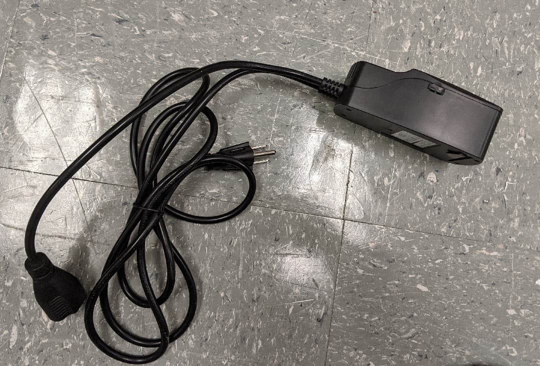
GTC-201705X
Mar 22, 2021L510 Lamp Controller
Equipment Class
DTS - Digital Transmission System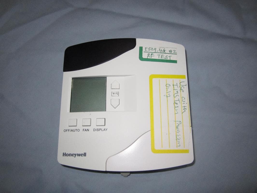
GTC202153TXR
Aug 27, 2014Battery Powered Thermostat
Equipment Class
DXX - Part 15 Low Power Communication Device Transmitter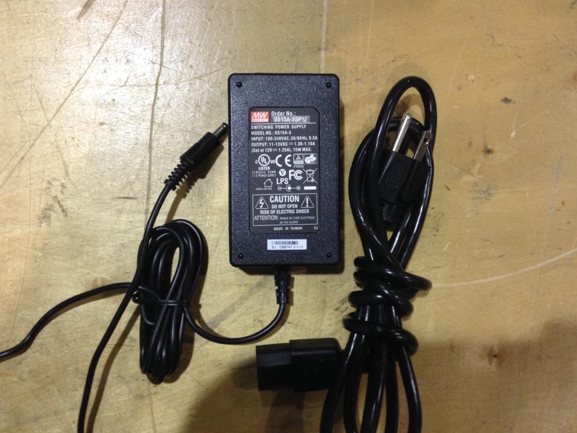
GTC201104TXR
Aug 26, 2014B578 Ethernet to RF Protocol Converter
Equipment Class
DXX - Part 15 Low Power Communication Device Transmitter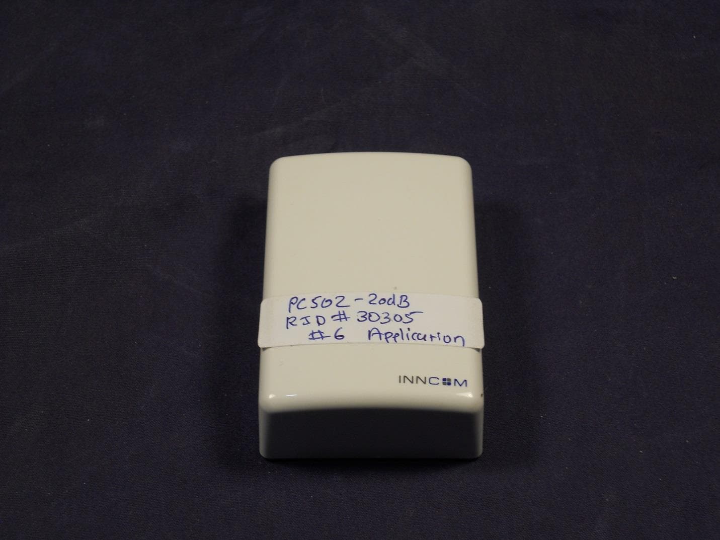
GTC202125TXR
Aug 17, 2014Wireless Repeater Module
Equipment Class
DTS - Digital Transmission System
GTC202124TXR
Sep 18, 2013Repeater
Equipment Class
DXX - Part 15 Low Power Communication Device Transmitter