GTC202111TXRSwitch
Honeywell International Inc.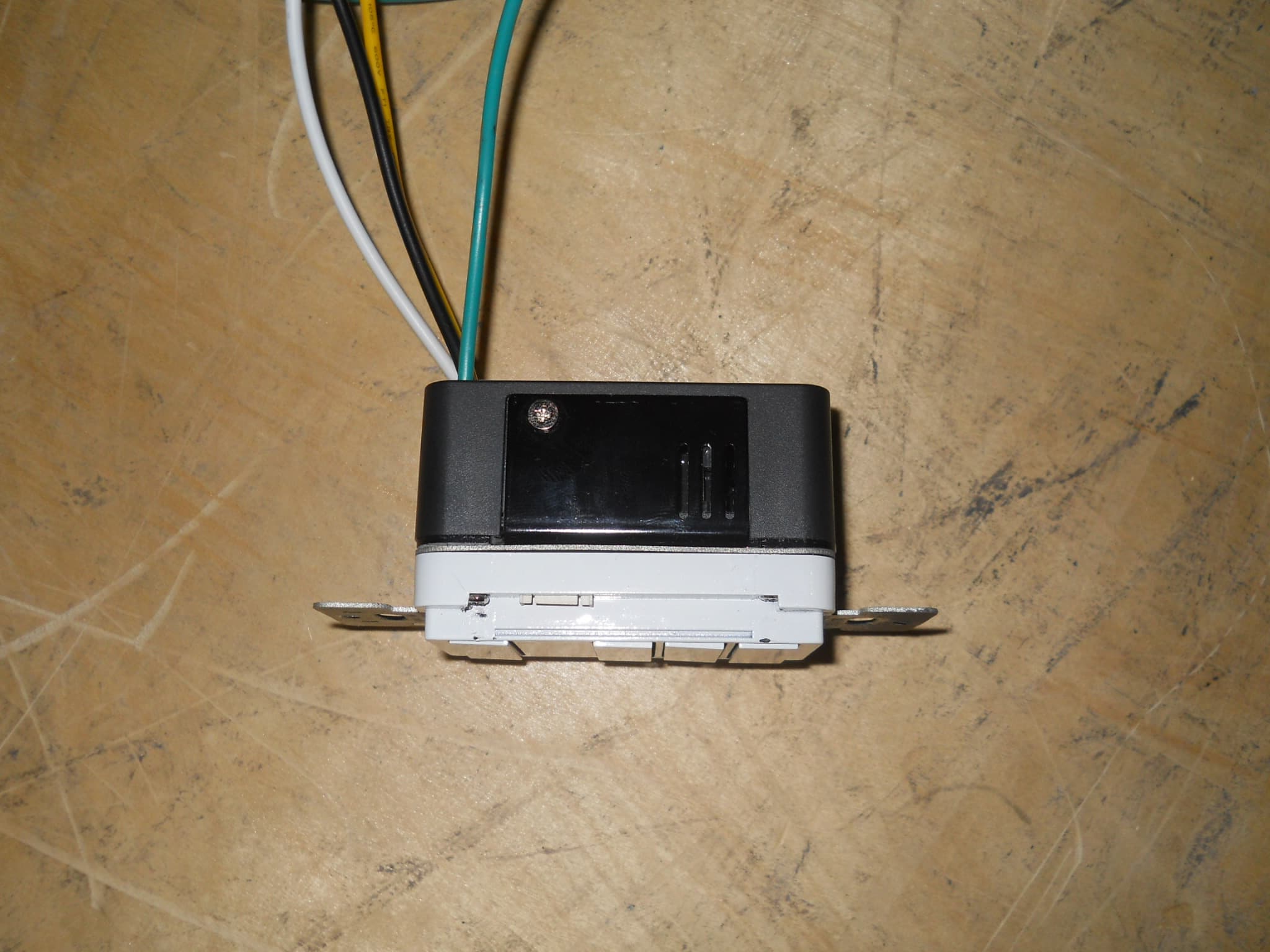
Click to zoom
Application Details
- Equipment Class
- DXX - Part 15 Low Power Communication Device Transmitter
- Date of Grant
- Oct 01, 2012
- Application Purpose
- Original Equipment
- Date of Application
- Oct 01, 2012
- Equipment Note
- Switch
- Frequency Range
- 2405.00000000 - 2480.00000000
- Company
- Honeywell International Inc.
- Country
- United States
Documents & Files
Document Text
Text extracted from the exhibit documents filed with the FCC. Open a document above to read the original.
Users Manual
Confidential Copyright © 2012 INNCOM EVORA Series Datasheet Overview The EVORA family of switches offers an elegantly designed, easy to use, feature-rich user interface and control system providing a state-of-the-art guestroom automation experience. EVORA allows guest control of multiple lighting loads, temperature, drapes, and guest annunciation from multiple switch locations in the guestroom. EVORA offers three different user interface modules and multiple different Load Assemblies that include wired and wireless communications, dimmers, and programmable controls designed to operate within INNCOM’s Integrated Room Automation System (IRAS). The EVORA system brings all guestroom control features into a sleekly designed traditional keypad user interface. Features • Up to 7 key configurations with up to 5 position key pad for programmable control of any IRAS feature • Nightlight configuration with 2 key positions • Doorbell configuration with 2 key positions • Optional multifunction key for up to 10 grouped features per device • Backlight illuminated keys and text • TRIAC dimmer • FET dimmer • Relay actuator • Master contactor application • 12VDC power supply • Low-voltage adapter for load center applications • 2.4Ghz 802.15.4 wireless RF network communications • S5bus wired network communications • Digital input for door switch contact / integration with the INNCOM energy management system (EMS) • Software programmable for any CBL feature Application EVORA was developed to extend INNCOM switch capabilities beyond those offered in the well-established S- Series (S217 and S5XX) product families and the innovative MODEVA series. The EVORA series uses a modular, cross functional hardware platform that allows each of the three main products (multifunctional switch, nightlight, and doorbell ) to share features in both hardware and software that were previously available only as uniquely designed sub-assemblies in the legacy S-Series products. EVORA has at its core the same Load Assembly (WBI) architecture used by INNCOM’s MODEVA line. The Load Assembly is available in six configurations—500W relay, 500W TRIAC dimmer, 350W FET dimmer, 30A master contactor, 200mA power supply, and a low-voltage adapter (LVA)—that provide the mechanical platform and load bearing capability for the EVORA system. The EVORA series differs from MODEVA in several ways. It uses a Figure 1 EVORA Switch E V O R A D a t a s h e e t P a g e 2 o f 1 0 standard dimension mounting bracket, for instance, allowing EVORAs to be ganged with other products (similar to the S-Series). EVORA products come factory assembled. Categories of Load Assembly Load Switching • TRIAC dimmer provides dimming control of resistive light loads such as incandescent, halogen, and TRIAC dimmable LEDs. The TRIAC dimmer can dim 100–120VAC loads up to 500W. • FET dimmer dims capacitive loads such as dimmable fluorescent lamps and electronic ballasts. It can also dim resistive loads such as incandescent, halogen, and dimmable LEDs. The FET dimmer is designed to dim 100–120VAC up to 350W. • Relay power supply switches capacitive, inductive, resistive, and general purpose loads up to 500W. • Master contactor controls 30A relay at 120–240VAC. • 200mA power supply used for applications where EVORA must be line powered but does not require load dimming or switching. • Low-voltage adapter allows the EVORA products to run in a +12VDC powered device that does not actuate a load. This is very similar to the legacy S5XX product. Load Assembly Parallel Power Supplies The WBI actuators operate in parallel to supply a higher load capacity on the +12VDC rail than that achievable by a single actuator. The total output power of the actuators in parallel is based on the voltage specifications at maximum load versus the output current at maximum load and nominal recovery time after a foldback condition occurs. This design can aggregate up to 6 actuators into a system that permits up to a combined 990mA (~1A) +12VDC output. See Class 2 Output table below. Additional Load Assembly Technical Features • Air-gap relay required (for dimmers meeting UL 508). Where solid state dimmers are used, disengages the load from the line power in the event that a failed actuator causes a short or a closed circuit (as with a FET dimmer), a possible electric shock risk during routine maintenance or lamp replacement. • Additional overload detection circuit for FET dimmer that senses a catastrophic overload / short and shuts down the dimmer to protect the solid state circuitry. • Dimming linearization curve may be set by application engineer to calibrate the duty cycle of a Pulse Width Modulated signal driving the various lamp types that could be used. • Self contained actuator that can be used without the user interface. This is useful during installation (with EVORA) and in repair to isolate symptoms related specifically to the actuator. Load Assembly Installation Locate the fuse panel and remove fuses or ensure the breaker is in the OFF position before installing the Load Assembly. 1. Pull the class-2 wires for Ground (Brown), +12VDC (Red) and S5bus (Orange) and digital inputs into the wall box (See Wiring Diagrams). Make the connections using a dolphin DC-1000P Super B connector or equivalent type connector to the S5bus or digital input harnesses and connect them to the appropriate header on the Load Assembly. 2. Prepare the line voltage wiring by stripping back the insulation 16mm (5/8th inch). 3. Connect the Green (Earth) Cable attached to the Load Assembly Strap to Earth. E V O R A D a t a s h e e t P a g e 3 o f 1 0 4. Wire the Load Assembly as described in the Wiring Diagrams. Depending on gang assembly using the appropriate 10, 12, 14, 16, or 18 AWG wire nut. 5. Push all wires back into the wall box and fasten the control to the wall box using the supplied mounting screws. Be sure not to pinch or disconnect any of the wires. 6. Ensure the intended load(s) are connected to the circuit.…
Text truncated - open the document above for the full version.
Cover Letter(s)
GTC202111TXR
External Photos
EM0594 Inncom External Photogaphs EM0594 Inncom External Photogaphs
External Photos
EM0594 Inncom External Photogaphs EM0594 Inncom External Photogaphs
ID Label/Location Info
IC: 1609A-201217TXR
Internal Photos
EM0594 Inncom Internal Photogaphs EM0594 Inncom Internal Photogaphs
Internal Photos
EM0594 Inncom Internal Photogaphs EM0594 Inncom Internal Photogaphs
Internal Photos
EM0594 Inncom Internal Photogaphs EM0594 Inncom Internal Photogaphs
Internal Photos
EM0594 Inncom Internal Photogaphs EM0594 Inncom Internal Photogaphs
Internal Photos
EM0594 Inncom Internal Photogaphs EM0594 Inncom Internal Photogaphs
Internal Photos
EM0594 Inncom Internal Photogaphs EM0594 Inncom Internal Photogaphs
Test Report
Curtis-Straus LLC is accredited by the American Association for Laboratory Accreditation for the specific scope of accreditation under Certificate Number 1627-01. This report may contain data which is not covered by the A2LA accreditation. ____________________________________________________________ Curtis-Straus LLC, a wholly owned subsidiary of BV CPS One Distribution Center Circle, #1 • •• • Littleton, MA • •• • TEL (978) 486-8880 • •• • FAX (978) 486-8828 page 1 of 20 Test Report Curtis-Straus LLC, a wholly owned subsidiary of BV CPS Report No EM0594-2 Client Inncom Ryan Gardner Address 277 West Main Street Niantic, CT 06357 Phone 860-739-4468 Items tested Evora Light Controller FCC ID GTC202111TXR IC ID 1609A-201217TXR FRN 0017924150 Equipment Type Low Power Communication Device Equipment Code DXX Emission Designator 2M41F7D Standards 47CFR 15.249, RSS 210 Issue 8 and RSS GEN Issue 3 Test Dates March 26, 28 and April 27, 2012 Results As detailed within this report Prepared by John Cushing – Test Engineer Authorized by Mairaj Hussain – EMC Supervisor Issue Date May 7, 2012 Conditions of Issue This Test Report is issued subject to the conditions stated in the ‘Conditions of Testing’ section on page 19 of this report. Test Report for Inncom • •• • Report No. EM0594-2 May 3, 2012 ______________________________________________________________________ ____________________________________________________________ Curtis-Straus LLC, a wholly owned subsidiary of BV CPS One Distribution Center Circle, #1 • •• • Littleton, MA • •• • TEL (978) 486-8880 • FAX (978) 486-8828 page 2 of 20 Contents Contents..................................................................................................................................2 Product Tested - Configuration Documentation .......................................................................3 Summary.................................................................................................................................4 Test Methodology ................................................................................................................4 Compliance Statement ............................................................................................................5 Modifications Required for Compliance ...................................................................................5 Test Results ............................................................................................................................6 Duty Cycle Correction Factor (DCCF) ..................................................................................6 Fundamental Measurements................................................................................................8 Band Edge Measurements...................................................................................................9 Radiated Spurious Emissions............................................................................................10 AC Line Conducted Emissions...........................................................................................14 Occupied Bandwidth..........................................................................................................16 Measurement Uncertainty......................................................................................................18 Conditions Of Testing ............................................................................................................19 Form Final Report REV 2-16-07 (DW) Test Report for Inncom • •• • Report No. EM0594-2 May 3, 2012 ______________________________________________________________________ _____________________________________________________________ Curtis-Straus LLC, a wholly owned subsidiary of BV CPS One Distribution Center Circle, #1 • •• • Littleton, MA • •• • TEL (978) 486-8880 • •• • FAX (978) 486-8828 page 3 of 20 Product Tested - Configuration Documentation EUT Configuration Work Order: M0594 Company: Inncom Company Address: 277 West Main Street Niantic, CT 06357 Contact: Ryan Gardner Person Present: Ryan Gardner MNPNSN EUT: 201-217---Sample 1 EUT Description: Evora Multibutton EUT Max Frequency:32MHz EUT Tx Frequency:2405-2480MHz Support Equipment: MNSN E527 Thermostat201-527Sample 1 EUT Ports: Port LabelPort Type No. of ports No. PopulatedCable TypeShieldedFerritesLength Max Length In/Out NEBS TypeUnpopulated Reason AC mainsPower AC113-wire ACNoNone1mN/Aindoor AC mains outputPower AC112-wire ACNoNone1mN/Aindoor Software / Operating Mode Description: EUT is used as a light dimming switch, where it sends a wireless transmission indicating the status of the light. EUT was also tested in standby/receive mode. Test Report for Inncom • •• • Report No. EM0594-2 May 3, 2012 ______________________________________________________________________ _____________________________________________________________ Curtis-Straus LLC, a wholly owned subsidiary of BV CPS One Distribution Center Circle, #1 • •• • Littleton, MA • •• • TEL (978) 486-8880 • •• • FAX (978) 486-8828 page 4 of 20 Summary This test report supports an application for certification of a transmitter operating pursuant to 47 CFR 15.249 and RSS-210. The product is the Evora Light Controller. It is a transmitter that operates in the range 2400 – 2483.5 MHz. We found that the product met the above requirements with modification (see Modifications Required for Compliance section on page 5). The test sample was received in good condition. Test Methodology Radiated emission and AC Line conducted testing was performed according to the procedures specified in ANSI C63.4 (2009) and RSS-GEN. Radiated Emissions were maximized by rotating the device around three orthogonal axes as well as varying the test antenna’s height and polarity. The device antenna cannot be maximized separately. The product was tested with modulation on and peak readings were compared against the average limit presented in…
Text truncated - open the document above for the full version.
Test Setup Photos
Test Setup Photogaphs Radiated Emissions - Front Test Setup Photogaphs Radiated Emissions - Back
Test Setup Photos
Test Setup Photogaphs Conducted Emissions - Front Test Setup Photogaphs Conducted Emissions - Back
Contact Information
Applicant
Jeanne Enaux(Sr. Quality Engineering Manager)
Test Firm
BUREAU VERITAS CONSUMER PRODUCTS SERVICES, INC.Ozgur Ozturk
[email protected]978-486-8880
Technical Specifications
| # | Rule Parts | Frequency Range | Power Output |
|---|---|---|---|
| 1 | 15C | 2.40 GHz - 2.48 GHz | - |
Other Applications from Honeywell International Inc.
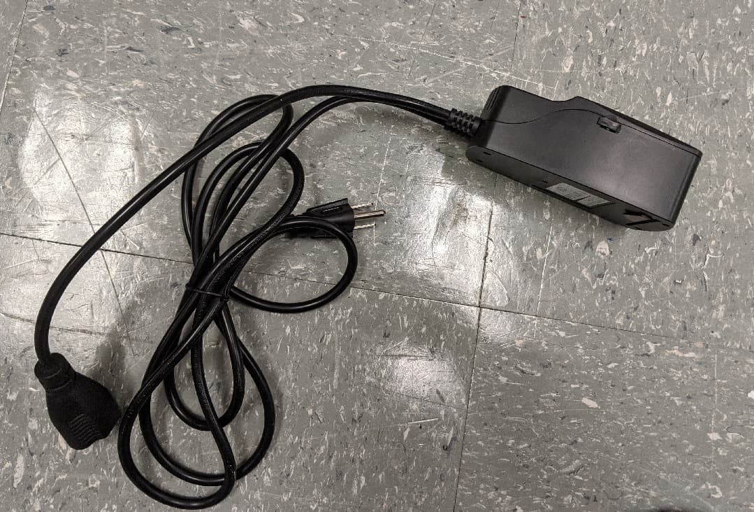
GTC-201705X
Mar 22, 2021L510 Lamp Controller
Equipment Class
DTS - Digital Transmission System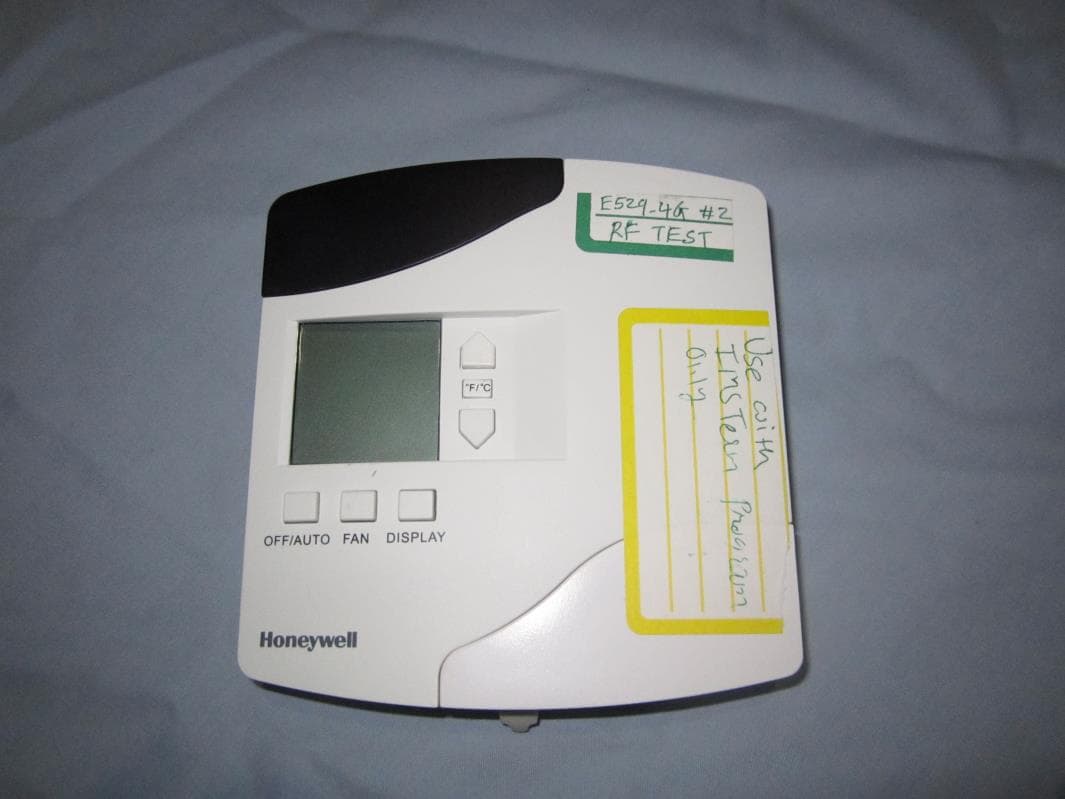
GTC202153TXR
Aug 27, 2014Battery Powered Thermostat
Equipment Class
DXX - Part 15 Low Power Communication Device Transmitter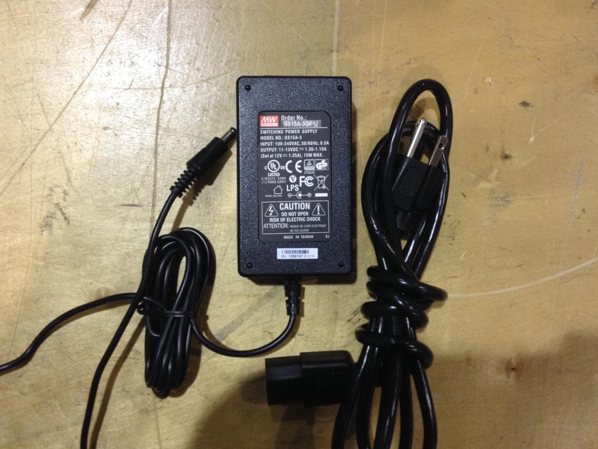
GTC201104TXR
Aug 26, 2014B578 Ethernet to RF Protocol Converter
Equipment Class
DXX - Part 15 Low Power Communication Device Transmitter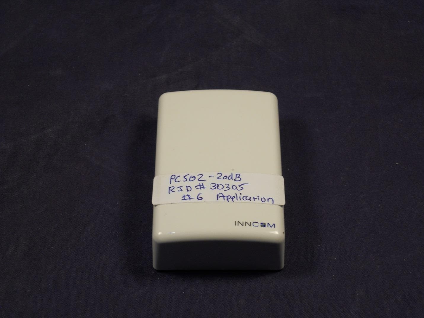
GTC202125TXR
Aug 17, 2014Wireless Repeater Module
Equipment Class
DTS - Digital Transmission System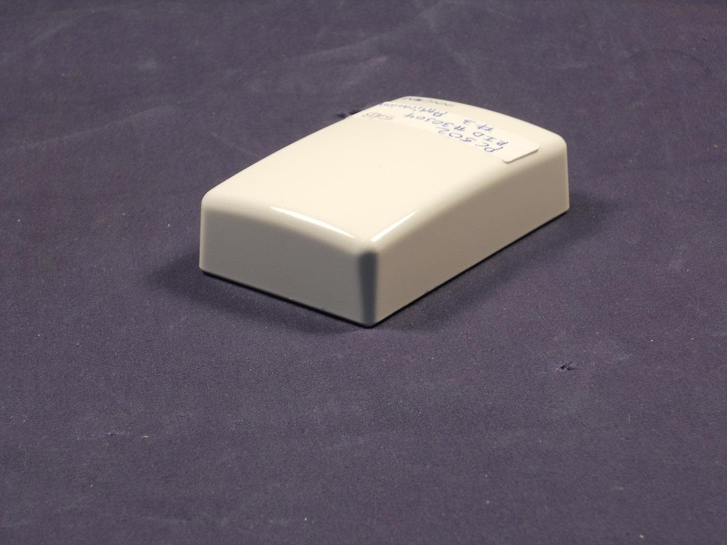
GTC202124TXR
Sep 18, 2013Repeater
Equipment Class
DXX - Part 15 Low Power Communication Device Transmitter