GTC202151TXRThermostat
Honeywell International Inc.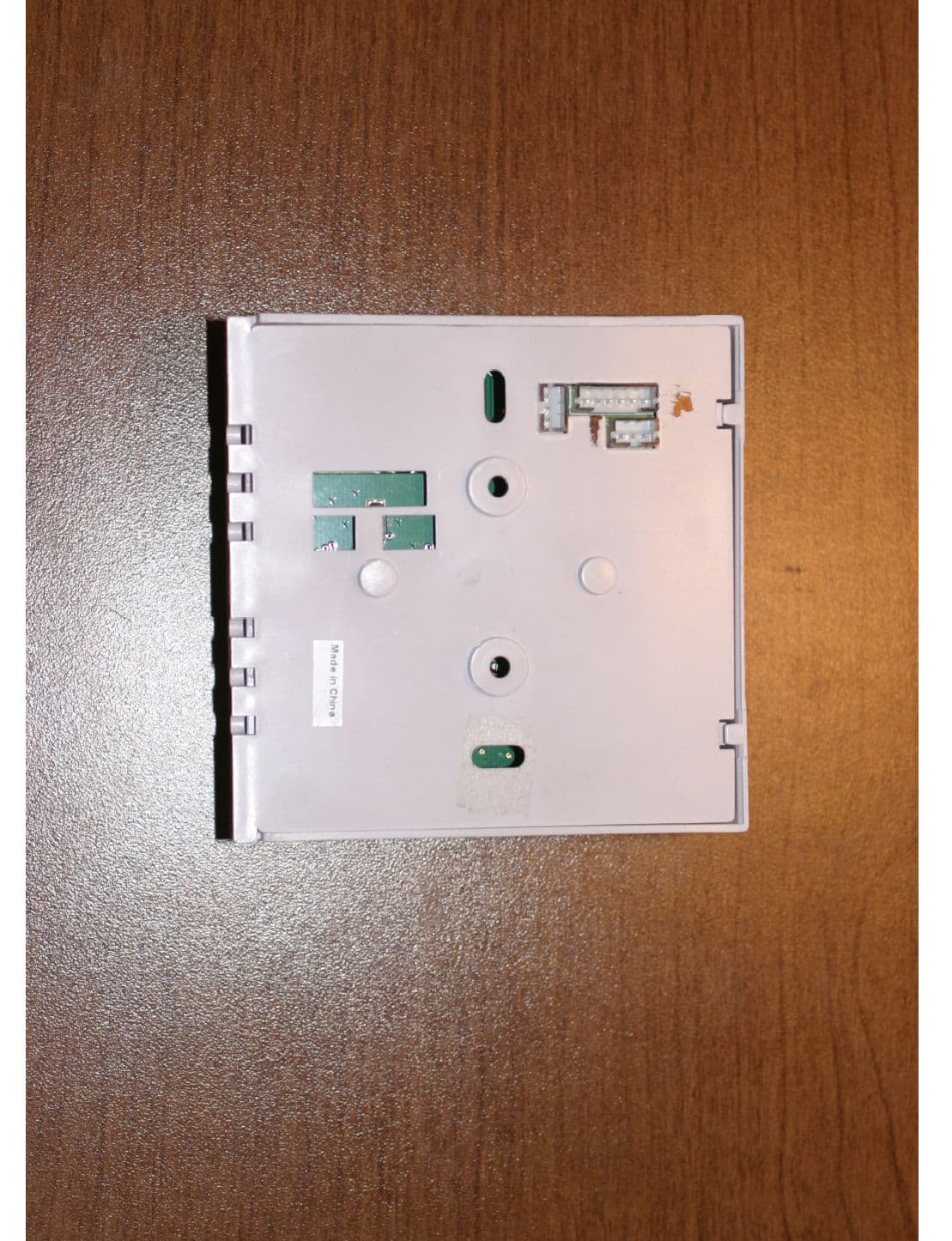
Click to zoom
Application Details
- Equipment Class
- DXX - Part 15 Low Power Communication Device Transmitter
- Date of Grant
- Oct 01, 2012
- Application Purpose
- Original Equipment
- Date of Application
- Oct 01, 2012
- Equipment Note
- Thermostat
- Frequency Range
- 2405.00000000 - 2480.00000000
- Company
- Honeywell International Inc.
- Country
- United States
Documents & Files
Document Text
Text extracted from the exhibit documents filed with the FCC. Open a document above to read the original.
Users Manual
Confidential Copyright © 2012 INNCOM e527 Datasheet Overview Like the larger e528, the compact, low profile e527 thermostat takes advantage of component end-of-life to redesign hardware and produce a more efficient, lower cost device. With onboard radio and RS485 connection and an added CDS light sensor, the e527 maintains its position as an integral part of the INNCOM Integrated Room Automation System (IRAS) and a property’s Energy Management System (EMS). Features In an EMS, the e527 controls room heating and cooling using occupancy data collected from motion detectors and door switches and can be networked to the property’s central management system. As an IRAS device, the e527 can communicate with devices within a room and function as a room gateway device towards the mesh network. • British gang mounting (American gang mounting with optional frame) • Accurate temperature measurement +/- 1 degree F • External temperature sensor support • Motion sensor for occupancy detection • RF transceiver (onboard 802.15.4, 2.4GHz radio) for wireless guestroom and backhaul network communications • RS485 for wired backhaul network communications • Photo sensor for light level detection Installation Requirements The e527 must be located on a partitioning interior wall, approximately 5' (1.5 m) above the floor, in a site of average temperature. It is important to ensure that the thermostat is located away from direct sunlight or radiant heat, air discharge grilles, stairwells, outside doors, steam or water pipes, warm air stacks, unheated/uncooled areas, or sources of electrical interference. The unit should not be placed on an outside wall or behind a door. The e527 is designed to be mounted on a standard British-style single-gang electrical box. For use with an American box, the e527 can be installed in an optional frame by means of two screws. Screws for attaching the optional frame and mounting the e527 are included. The device is shipped with a clear clamshell dust cover. Figure 1 E527 E 5 2 7 D a t a s h e e t P a g e 2 o f 7 Headers H1 ICP microprocessor programming H2 Humidity sensor H3 System interconnect H4 PIR sensor H5 ES1 H6 RS485 network header (see pinout below) H7 System 5 header (see pinout below) H8 System interconnect H9 External temperature control sensor (see pinout below) H6 Pinout Pin Function Comment 1 Common GND Min Nom Max 2 12VDC 10V 12V 14V 3 S5bus Communication bus 4 Dry Input Input 5 RS485B RS485 Twisted Pair 6 RS485A RS485 Twisted Pair Figure 2 E527 Front/Back and External Headers E 5 2 7 D a t a s h e e t P a g e 3 o f 7 H7 Pinout Pin Function Comment 1 Common GND Min Nom Max 2 12VDC 10V 12V 14V 3 S5bus Communication bus H9 Pinout Pin Function Comment 1 Common GND 2 Common GND 3 External temp sensor Motion Detection The optional motion detector available on the e527 works in conjunction with the electronic door lock to determine room occupancy. If the door lock reports that the door has opened and closed and no motion is detected in the room for a set number of minutes, the e527 engages energy conservation setbacks. When motion is detected, the e527 returns to its occupied state. Also, the e527 reports occupancy changes to the central server. Figure 3 Motion Sensor Sensitivity E 5 2 7 D a t a s h e e t P a g e 4 o f 7 Network Communication INNCOM employs a Deep Mesh system to connect guestroom IRAS components to management and monitoring servers. Because networking infrastructure is embedded in the IRAS devices, command and reporting information packets can follow multiple network pathways, increasing communication efficiency and reliability at lower cost. Typically, a Deep Mesh network integrates 50–200 rooms per network segment * . INNCOM generally uses a wireless radio network, but a Deep Mesh system may be constructed using RS485 networks (topologies that merge RF and RS485 networks are also possible). 2.4GHz Wireless RF In a typical RF Deep Mesh network, an 802.15.4-based 2.4GHz radio-equipped IRAS device (most often a thermostat, such as the e527) acts as a room gateway for communication with the network. Data are propagated among the network nodes until terminated at edge routers that bridge traffic onto IP (Ethernet) networks towards the servers. The radio specifications are given in the table below: Performance 0dB RF Data Rate 250kbps Antenna Type SMT Indoor Range 70ft Outdoor/ RF line-of-sight range 540ft Transmit Power 1mW Receive Sensitivity -94.6dBm Frequency Band 2.4GHz Encryption AES-128 Protocol 802.15.4 Frequency Channels 11–26 This equipment has been tested and found to comply with the limits for a Class B digital device, pursuant to Part 15 of the FCC Rules. These limits are designed to provide reasonable protection against harmful interference in a residential installation. This equipment generates uses and can radiate radio frequency energy and, if not installed and used in accordance with the instructions, may cause harmful interference to radio communications. However, there is no guarantee that interference will not occur in a particular installation. If this equipment does cause harmful interference to radio or television reception, which can be determined by turning the equipment off and on, the user is encouraged to try to correct the interference by one of the following measures: - Reorient or relocate the receiving antenna. - Increase the separation between the equipment and receiver. - Connect the equipment into an outlet on a circuit different from that to which the receiver is connected. - Consult the dealer or an experienced radio/TV technician for help. Any changes or modifications not expressly approved by the party responsible for compliance could void the user's authority to operate this equipment. * The network segment size depends on the facility’s layout, expected network traffic, and other environmental considerations. E 5 2 7 D a t a s h e e t P a g e 5 o f 7 This device complies with Industry Canada licence-exempt RSS standar…
Text truncated - open the document above for the full version.
Cover Letter(s)
07/11/2012 To: Federal Communications Commission 7435 Oakland Mills Road Columbia, MD 21046-1609 Curtis-Straus LLC TCB One Distribution Center Circle, #1 Littleton, MA 0 1460 Re: Confidentiality Request Gentlemen: This letter is to comply with 47 CFR 0.457(d)(2) pertaining to confidential material. INNCOM International Inc. requests that the following documents regarding this submission for FCC ID: GTC202151TXR be kept confidential: 1. Schematics 2. Block Diagram 3. Circuit/Technical Description The material above contains technical data, which would customarily be guarded from competitors. 7/11/2012
Test Report
Curtis-Straus LLC is accredited by the American Association for Laboratory Accreditation for the specific scope of accreditation under Certificate Number 1627-01. This report may contain data which is not covered by the A2LA accreditation. ____________________________________________________________ Curtis-Straus LLC, a wholly owned subsidiary of BV CPS One Distribution Center Circle, #1 • •• • Littleton, MA • •• • TEL (978) 486-8880 • •• • FAX (978) 486-8828 page 1 of 19 Test Report Curtis-Straus LLC, a wholly owned subsidiary of BV CPS Report No EM0593-2 Client Inncom Ryan Gardner Address 277 West Main Street Niantic, CT 06357 Phone 860-739-4468 Items tested E527.4G Thermostat FCC ID GTC202151TXR IC ID 1609A-202151TXR FRN 0017924150 Equipment Type Low Power Communication Device Transmitter Equipment Code DXX Emission Designator 2M41F7D Standards 47CFR 15.249, RSS 210 Issue 8 and RSS GEN Issue 3 Test Dates March 26, 28 and April 27, 2012 Results As detailed within this report Prepared by John Cushing – Test Engineer Authorized by Mairaj Hussain – EMC Supervisor Issue Date May 7, 2012 Conditions of Issue This Test Report is issued subject to the conditions stated in the ‘Conditions of Testing’ section on page 18 of this report. Test Report for Inncom • •• • Report No. EM0593-2 May 7, 2012 ______________________________________________________________________ ____________________________________________________________ Curtis-Straus LLC, a wholly owned subsidiary of BV CPS One Distribution Center Circle, #1 • •• • Littleton, MA • •• • TEL (978) 486-8880 • FAX (978) 486-8828 page 2 of 19 Contents Contents..................................................................................................................................2 Product Tested - Configuration Documentation .......................................................................3 Summary.................................................................................................................................4 Test Methodology ................................................................................................................4 Compliance Statement ............................................................................................................5 Test Results ............................................................................................................................6 Duty Cycle Correction Factor (DCCF) ..................................................................................6 Fundamental Measurements................................................................................................8 Band Edge Measurements...................................................................................................9 Radiated Spurious Emissions............................................................................................10 AC Line Conducted Emissions...........................................................................................14 Occupied Bandwidth..........................................................................................................15 Measurement Uncertainty......................................................................................................17 Conditions Of Testing........................................................................................................18 Form Final Report REV 2-16-07 (DW) Test Report for Inncom • •• • Report No. EM0593-2 May 7, 2012 ______________________________________________________________________ _____________________________________________________________ Curtis-Straus LLC, a wholly owned subsidiary of BV CPS One Distribution Center Circle, #1 • •• • Littleton, MA • •• • TEL (978) 486-8880 • •• • FAX (978) 486-8828 page 3 of 19 Product Tested - Configuration Documentation EUT Configuration Work Order:M0593 Company:Inncom Company Address:277 West Main Street Niantic, CT 06357 Contact:Ryan Gardner Person Present:Ryan Gardner MNPNSN EUT:201-527---Sample 1 EUT Description:E527 4G Thermostat EUT Max Frequency: 32MHz EUT Tx Frequency: 2405-2480MHz Support Equipment: MNSN Evora Multibutton201-217Sample 1 Power Supply01-992012939 EUT Ports: Port LabelPort TypeNo. of ports No. PopulatedCable TypeShieldedFerritesLength Max Length In/Out NEBS Type Unpopulated Reason S5 busPower and Communication1124awgNoNone1.5m10mindoor H6Power and Communication10Not supported H9external temp1124awgNoNone1.5m10mindoor Software / Operating Mode Description: EUT is wirelessly pinging the Evora Multibutton. EUT was also tested in standby/receive mode. Test Report for Inncom • •• • Report No. EM0593-2 May 7, 2012 ______________________________________________________________________ _____________________________________________________________ Curtis-Straus LLC, a wholly owned subsidiary of BV CPS One Distribution Center Circle, #1 • •• • Littleton, MA • •• • TEL (978) 486-8880 • •• • FAX (978) 486-8828 page 4 of 19 Summary This test report supports an application for certification of a transmitter operating pursuant to 47 CFR 15.249 and RSS-210. The product is the E527.4G Thermostat. It is a transmitter that operates in the range 2400 – 2483.5 MHz. We found that the product met the above requirements without modification. The test sample was received in good condition. Test Methodology Radiated emission and AC Line conducted testing was performed according to the procedures specified in ANSI C63.4 (2009) and RSS-GEN. Radiated Emissions were maximized by rotating the device around three orthogonal axes as well as varying the test antenna’s height and polarity. The device antenna cannot be maximized separately. The product was tested with modulation on and peak readings were compared against the average limit presented in section CFR 15.249. The EUT operating voltage is 120V/60Hz. The following bandwidths were used during radiated spurious and line conducted emissions. Frequency RBW VBW 0.15-30MHz 9kH…
Text truncated - open the document above for the full version.
Contact Information
Applicant
Jeanne Enaux(Sr. Quality Engineering Manager)
Test Firm
BUREAU VERITAS CONSUMER PRODUCTS SERVICES, INC.Ozgur Ozturk
[email protected]978-486-8880
Technical Specifications
| # | Rule Parts | Frequency Range | Power Output |
|---|---|---|---|
| 1 | 15C | 2.40 GHz - 2.48 GHz | - |
Other Applications from Honeywell International Inc.
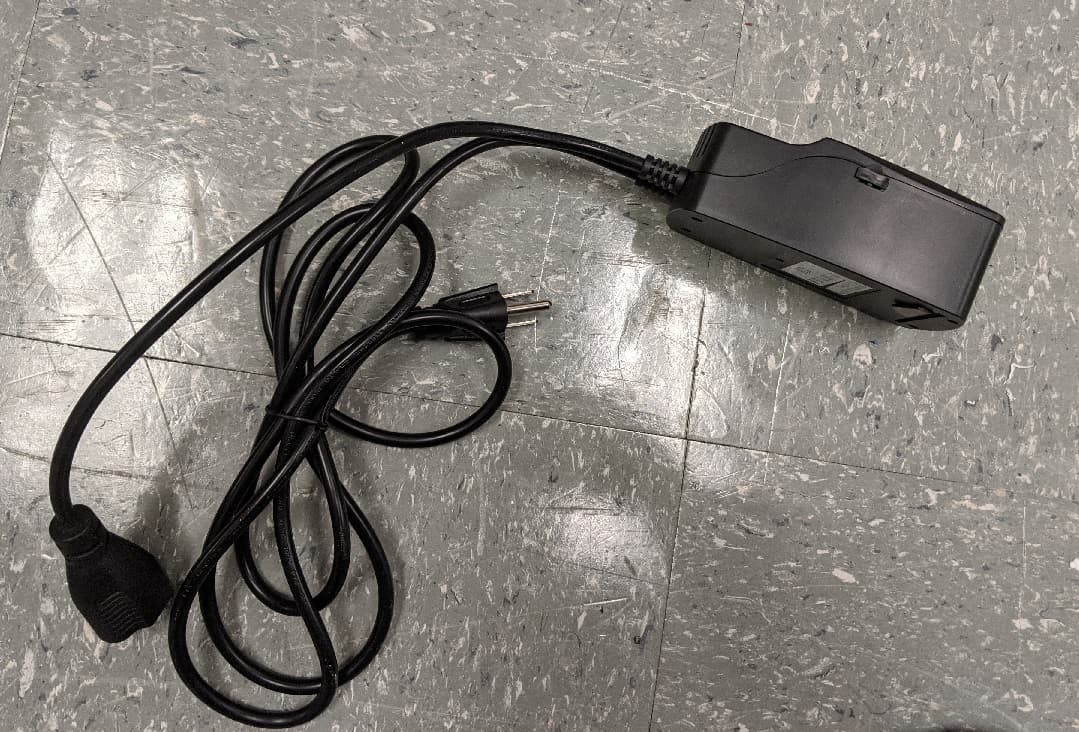
GTC-201705X
Mar 22, 2021L510 Lamp Controller
Equipment Class
DTS - Digital Transmission System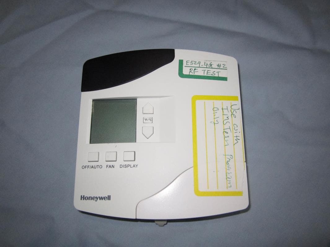
GTC202153TXR
Aug 27, 2014Battery Powered Thermostat
Equipment Class
DXX - Part 15 Low Power Communication Device Transmitter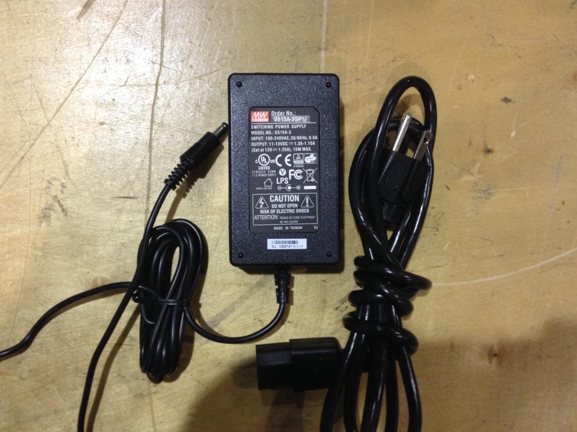
GTC201104TXR
Aug 26, 2014B578 Ethernet to RF Protocol Converter
Equipment Class
DXX - Part 15 Low Power Communication Device Transmitter
GTC202125TXR
Aug 17, 2014Wireless Repeater Module
Equipment Class
DTS - Digital Transmission System
GTC202124TXR
Sep 18, 2013Repeater
Equipment Class
DXX - Part 15 Low Power Communication Device Transmitter