H2WCASA11TRemote control for ceiling fan
Hunter Fan Company
Click to zoom
Application Details
- Equipment Class
- DSC - Part 15 Security/Remote Control Transmitter
- Date of Grant
- Jan 19, 2010
- Application Purpose
- Original Equipment
- Date of Application
- Jan 19, 2010
- Equipment Note
- Remote control for ceiling fan
- Frequency Range
- 303.00000000 - 303.00000000
- Company
- Hunter Fan Company
- Country
- United States
Documents & Files
Document Text
Text extracted from the exhibit documents filed with the FCC. Open a document above to read the original.
Users Manual
To control the fan and lights from two locations (a three-way circuit), use two W-74 wall controls. 1. Remove the screws and switch plate from the existing switch box and the screws holding the switch in the switch box. 2. Pull the existing switch from the switch box to expose the wire connections. 3. Determine which wire is connected to the common terminal from the power source (120V AC) of the three-way switch. (The terminal will be marked on switch). 4. Remove the wire from the common terminal of the three-way switch. Connect this wire to the remaining black/white striped wire on the W-74 control. Secure this splice with a wire nut. 5. Remove the two remaining wires from the three-way switch. Connect the black wire of these wires to a black wire on the W-74 control. Secure the splice with a wire nut. The remaining red wire is to be connected to the other red wire on the W-74. Secure the splice with a wire nut. 6. Connect the green ground wire coming from the back of the W-74 control to the ground wire in the switch box. Secure the splice with a wire nut. 7. Check your work by using the wiring diagrams as shown in Figure #5 on this page. 8. Install the W-74 in the wall box with the two long screws provided. 9.Install the wall plate with the two short color-matched screws provided. 10.Installation of the second W-74 control is identical. Repeat steps 1 through 9. W-74 WALL CONTROL INSTALLATION (For use on product with BOTH UP and DOWN LIGHTS ONLY) Setting the Frequency DIP SWITCHES (FIGURE #2) To use this switch with an existing W-74 wall switch, you must first set the jumpers on the new switch to match that of the existing one. 1. Turn off power to the existing wall switch. 2. Using a screw driver, remove the (2) wall plate screws, then remove the (2) switch mounting screws. 3. Gently remove the existing wall switch from the wall and locate the dip switches located on the side of the switch. 4. Change the dip switches on the new wall switch to match the exisiting. (FIGURE 2) 5. Reinstall the existing wall switch. inStalling the Wall control The wall control installs in the same manner as an ordinary light switch, using an existing wall box and wiring. This controller is designed to signal the fan microcomputer as well as perform normal switching operations. For this reason the following precautions must be observed: 1. Use only the Casablanca W-74 wall control. 2. Do not use any additional control with your Direct-Touch™ fan (for example, dimmer, or fan speed control). 3. Do not use more than one fan per wall control. 4. No other light fixtures or electrical appliances may be connected on the circuit con- trolled by the W-74 wall control. single W-74 installation CAUTION! Ensure power is turned OFF at the breaker or fuse panel before starting installation. If you have multiple Direct-Touch ™ fans, refer to the section "Channel Changing". 1. Remove the screws and switch plate from the existing switch box. 2. Remove the screws holding the switch in the switch box. 3. Pull the existing switch from the switch box to expose the wire connections. 4. Remove the two wires from the switch. 5. Connect the BLACK wire from the POWER SOURCE that you just removed from the switch to the BLACK/WHITE STRIP wire on the W-74 wall control. Secure this connection with a wire nut. 6. Connect the second BLACK wire that you just removed from the switch to the second BLACK wire on the located on the back of the W-74 wall control. Secure this connection with a wire nut. 7. Connect the green ground wire coming from the back of the W-74 control to the ground wire in the switch box. Secure the splice with a wire nut. NOTE: The RED wire is not used in this application. DO NOT remove the crimped cap from the wire. 8. Check your work by using the wiring diagrams as shown in Figure #3. 9. Install the W-74 in the wall box with the two long screws provided. 10. Install the wall plate with the two color-matched screws. Dual W-74 installation To control the fan and lights from two locations (a three- way circuit), use two W-74 wall controls as shown in the wiring diagram in Figure #5. Before installing the two switches into the wall, place both switches side by side, then locate the 4 dip switches on the side of the two switches. Then make sure that the dip switches are set to the same address on both switches as shown in Figure #4. When setting these dip switches you are setting the channel number that is required to control both your fan and lights from both sides of the room. If you are installing other Direct-Touch™ fans within your home you may need to reset the dip switches on these other fans to a different channel before installing your W-74 wall control into the wall. Please review the section on channel changing on this instruction sheet. channel changing Each fan must operate on it’s own frequency to prevent interference. Fan frequencies are set by the dip switch settings on the W-74 wall control (other than to match an existing W-74 controlling the same fan). To synchronize the fan to the new frequncy: 1. Turn the power OFF to the fan and W-74 you want to synchronize. 2. Turn the power back on to the fan and W-74 wall control. 3. Within 20 seconds of restoring power to the ceiling fan and the W-74 Wall Control press and hold both the “1” and 1 2 0 4 3 reverse buttons. For 3 seconds, you will hear one tone from the Piezo Buzzer indicating the command has been accepted. The Fan and Lights will be off. CAUTION! Ensure power is turned OFF at the breaker or fuse panel before starting installation. W-74 Wall control HardWare Wall Plate Screws (2) Switch Mounting Screws (2) (4) Wire Cap W-74 Wall Control Cover Plate Warning! To avoid possible electrical shock, make certain that electricity is turned off at the circuit breaker or fuse box before attempting any installation or repair procedure CAUTION! NOT turning the power OFF at the circuit breaker or fuse box may cause damage to the electronics within the wall contr…
Text truncated - open the document above for the full version.
Block Diagram
RECEIVER ANT MIXER DETECTER O.S.C AMPLIFIER DIGITAL DECODE CONTROL CIRCUIT DRIVER CIRCUIT MOTOR UNIT LAMP UNIT BUTTON SWITCH U2 MCU ENCODE RF 303.5Mhz O.S.C MODULATOR DP-SW 4Mhz X1 303.5Mhz SAW1 TRANSMITTER Q4 REGULATOR 3.3V 3.3v to MCU AC/DC Power supply Power Switch AC120V Memory Live RX power supply Neutral Ant
Operational Description
HUND741 RF module Circuit Description Transmitter 1. Power Supply: An electronic circuit capable of converting 120Vac and stepping down the voltage to a regulated +3.3VDC to Transmitter MCU and RF module. 2. Power Switch: The TX power switch to controller the Power ON/OFF of the Transmitter and fan light control receiver. 3. Function: The HUND741 to control the FAN speed/Reverse and Light dimming function through 303.5MHz RF signal. 3. Harmonic Filter: The harmonic filter is build of C4, C5, C6, L1, L2 in order to reduce the harmonic signal to meet FCC regulation. 5. ID SW setting: The 6 Switch DIP to setting the address cord for the usage of multiple Receivers. 6. Antenna: A 303.5MHz rectangular loop antenna is used to transmit carrier RF signal.
Schematics
3/DEC/09 URU TRANSMITTER V3 CB CAI 5 4 3 AB C B Computime A SCALE: SHEET: OF DRAWING NO: TITLE:COMPANY: RELEASED: DATED: DATED: QUALITY CONTROL:CHECKED: DATED: DATED: DRAWN: CODE: SIZE: REV: 1 1 B C 2 1 DATE: LTR ECO NO: APPROVED: REVISION RECORD PT4450 HUN32RF C9 (PF) C6(PF) URU AT Remote 4.7 27 5 200 R3 (ohm) 3301.2K C7(PF) 1 NOT USE C4200PF200PF 18NH W74DL 4.7 27 470 1 1 OSCOUT 2 GND 3 PAOUT 6 OSCIN 5 VDD 4 CE U1 Y1 303.5MHZ L1 220NH L2 27NH C1 0.1UF C2 47PF C3 47PF C4 ?? C55PF C6?? C7NOT USE C81PF R1 10K R2 NOT USE R3 ?? 1 DATA 2 VDD 3 GND P1 ANT1ANT2 C9 ?? VDD
Schematics
12/OCT/2009 3 Wy Qu Direct Touch Computime. Ltd B 1 2 REV: SIZE: CODE: DRAWN: DATED: DATED: CHECKED:QUALITY CONTROL: DATED: DATED: RELEASED: COMPANY:TITLE: DRAWING NO: SHEET: OF SCALE: REVISION RECORD APPROVED: ECO NO: ABD DATE: 1 2 3 4 5 6 DCAB C LTR Logic Output Fan1 S3F9454 1 VSS 2 P1.0 3 P1.1 4 P1.2 5 P2.0 6 P2.1 7 P2.2 8 P2.3 9 P2.4 10 P2.5 20 VDD 19 P0.0 18 P0.1 17 P0.2 16 P0.3 15 P0.4 14 P0.5 13 P0.6 12 P0.7 11 P2.6 U3 Fan2 Fan3 3 1 2 X1 4MHz C7 0.1uf R2 100k R5 100k L4 220NH L5 220NH 15236 7 4 8 9 10 11 12 S2 RECODE_12P Fan4 Reverse Uplight Downlight Fan Off D3 D4 S G D Q2Q/MOSFET/P/ENH/BSS84 BSS84 R7 10k J1 J2 R8 10k C12 0.1uf BLK1 3.3V_RETURN_TO_PS +3.3V 3.3V_FROM_PS +3.3V RF_VDD RF_OUTPUT +3.3V 12/OCT/2009 Direct Touch 3 Wy Qu Computime. Ltd B 2 2 REV: SIZE: CODE: DRAWN: DATED: DATED: CHECKED:QUALITY CONTROL: DATED: DATED: RELEASED: COMPANY:TITLE: DRAWING NO: SHEET: OF SCALE: REVISION RECORD APPROVED: ECO NO: ABD DATE: 1 2 3 4 5 6 DCAB C LTR Power board ON OFF * * + C40 470uF 16V Q4 CZ-3.3V + C30220uF 16V 2 31 SW2-A 5 64 SW2-B D1 5.6V 1 3 2 Q1 * BTA08 4 - 3 + 1 AC1 2 AC2 D7 DIODE/DB104 R6 510R C100.1uF C20.1uF REDBLK BLK1 +3.3V
Test Report
Client: Product Designation: W74 RF Wall Control Report Number: 3197666ATL-001 All services undertaken are subject to the following general policy: This report is for the exclusive use of Intertek's Client and is provided pursuant to the agreement between Intertek and its Client. Intertek's responsibility and liability are limited to the terms and conditions of the agreement. Intertek assumes no liability to any party, other than to the Client in accordance with the agreement, for any loss, expense or damage occasioned by the use of this report. Only the Client is authorized to copy or distribute this report and then only in its entirety. Any use of the Intertek name or one of its marks for the sale or advertisement of the tested material, product or service must first be approved in writing by Intertek. The observations and test results in this report are relevant only to the sample tested. This report by itself does not imply that the material, product, or service is or has ever been under an Intertek certification program. This report must not be used to claim product endorsement by A2LA, NIST, or any agency of the US Government. Tested by: Tests performed by:Report reviewed by: Standard: Jeremy O. Pickens EMC Department Manager Chris D. Capelle Senior Project Engineer Hunter Fan 7130 Goodlett Farms Pkwy Suite 400 Memphis, TN38016 Contact: Robert Davis Phone: 901.248.2212 Fax: 901.248.2382 TEST REPORT December 31, 2009 Intertek Testing Services NA Inc. 1950 Evergreen Blvd., Suite 100 Duluth, GA30096 47 CFR Part 15, Subpart C (15.231 - Periodic operation in the band 40.66- 40.70 MHz and above 70 MHz) RSS-210, Issue 7, 2007 Page 1 of 26EMC Report for Hunter Fan on the W74 RF Wall Control 12/31/2009Report Number: 3197666ATL-001Issued: Intertek 2.0 Test Summary 2.0 Test Summary2.0 Test Summary 2.0 Test Summary 1.0 Introduction and Conclusion 1.0 Introduction and Conclusion1.0 Introduction and Conclusion 1.0 Introduction and Conclusion Test DateTest Full NameResultSection System setup including cable interconnection details, support equipment and simplified block diagram. (SystemSetup)4.0 Overview of EUT (Low Power Transmitters) (FCC 15C - EUT Overview)5.0 12/15/2009Restrictions (FCC 15C - 15.231(a))PASS6.0 12/15/2009Duty Cycle Determination (FCC 15A - 15.35(c))PASS7.0 12/17/2009Radiated Emissions (FCC 15C - 15.231(b))PASS8.0 12/30/2009Conducted emissions on AC power lines (Conducted Emissions)PASS9.0 12/15/2009Bandwidth Requirements (FCC 15C - 15.231(c))PASS10.0 The tests indicated in section 2.0 were performed on the product constructed as described in section 3.0. The remaining test sections are the verbatum text fromthe actual data sheets used during the investigation. These test sections include the test name, the specified test Method, a list of the actual Test Equipment Used, documentation Photos, Results and raw Data. No additions, deviations, or exclusions have been made from the standard(s) unless specifically noted. Based on the results of our investigation, we have concluded the product tested complies with the requirements of the standard(s) indicated. The results obtained in this test report pertain only to the item(s) tested. Page 2 of 26 EMC Report for Hunter Fan on the W74 RF Wall Control 12/31/2009Report Number: 3197666ATL-001Issued: Intertek 3.0 Description of Equipment Under Test 3.0 Description of Equipment Under Test3.0 Description of Equipment Under Test 3.0 Description of Equipment Under Test Equipment Under Test DescriptionManufacturerModel NumberSerial Number Fan/Light ControllerHunter FanW74Not Labeled EUT receive date:December 15, 2009 EUT receive condition:Good Description of EUT provided by Client: The W74 is a wll mount wireless fan/light controller designed to work with Direct-Touchôfans. The controller employs fan speed, light dimming, and fan reverse functions. Description of EUT exercising: During testing, the controller was configured to transmit continuously by depressing the light dimming control button. Page 3 of 26EMC Report for Hunter Fan on the W74 RF Wall Control 12/31/2009Report Number: 3197666ATL-001Issued: Intertek System setup including cable interconnection details, support equipment and simplified block System setup including cable interconnection details, support equipment and simplified blockSystem setup including cable interconnection details, support equipment and simplified block System setup including cable interconnection details, support equipment and simplified block diagram. (System Setup) diagram. (System Setup)diagram. (System Setup) diagram. (System Setup) 4.0 4.04.0 4.0 Method: Record the details of EUTcabling, document the support equipment, and show the interconnections in a block diagram. White (Neutral) Black/White Blue Black White (Common) Red Black/White Tx Rx AC Mains 120VAC/60Hz LGN Black Red Inside ChamberOut side Chamber Setup Diagram Drawing: Page 4 of 26EMC Report for Hunter Fan on the W74 RF Wall Control 12/31/2009Report Number: 3197666ATL-001Issued: Intertek System setup including cable interconnection details, support equipment and simplified block System setup including cable interconnection details, support equipment and simplified blockSystem setup including cable interconnection details, support equipment and simplified block System setup including cable interconnection details, support equipment and simplified block diagram. (System Setup) diagram. (System Setup)diagram. (System Setup) diagram. (System Setup) 4.0 4.04.0 4.0 A B Description EUT Cabling Connection LengthShieldingFerritesIDFromTo AC MainsWall Transmitter Wall TransmitterReceiver AC Input1.5m Tx AC Output15.0mNoneNone NoneNone None Required Support Equipment DescriptionManufacturerModel NumberSerial Number Data: Page 5 of 26EMC Report for Hunter Fan on the W74 RF Wall Control 12/31/2009Report Number: 3197666ATL-001Issued: Intertek Overview of EUT (Low Power Transmitters) (FCC 15C - EUT Overview) Overview of EUT (Low Power Transmitters) (FCC 15C …
Text truncated - open the document above for the full version.
Contact Information
Applicant
Julian A Martin(Compliance Manager)
Test Firm
Intertek Testing Services NA Inc.Charles Parker
Technical Specifications
| # | Rule Parts | Frequency Range | Power Output |
|---|---|---|---|
| 1 | 15.231 | 303 MHz - 303 MHz | - |
Other Applications from Hunter Fan Company
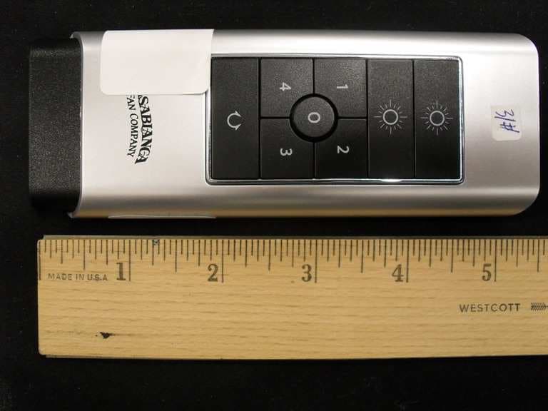
H2WCASA12T
Nov 28, 2010Remote control for ceiling fan
Equipment Class
DSR - Part 15 Remote Control/Security Device Transceiver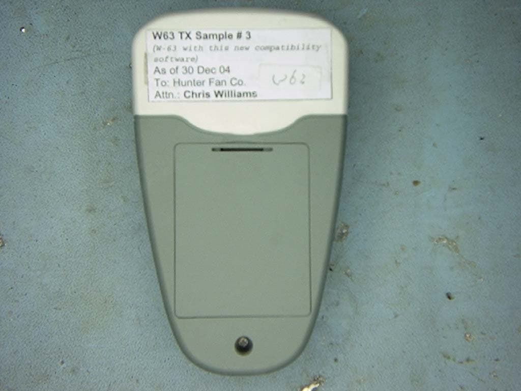
H2WCASA7T
Jul 19, 2005Fan and Light Control Transmitter
Equipment Class
DSC - Part 15 Security/Remote Control Transmitter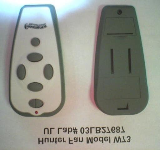
H2WCASA8T
Jun 17, 2004Ceiling fan remote control transmitter
Equipment Class
DSC - Part 15 Security/Remote Control Transmitter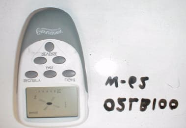
H2WCASA6T
Mar 28, 2002Ceiling fan and lamp remote contro.
Equipment Class
DSC - Part 15 Security/Remote Control Transmitter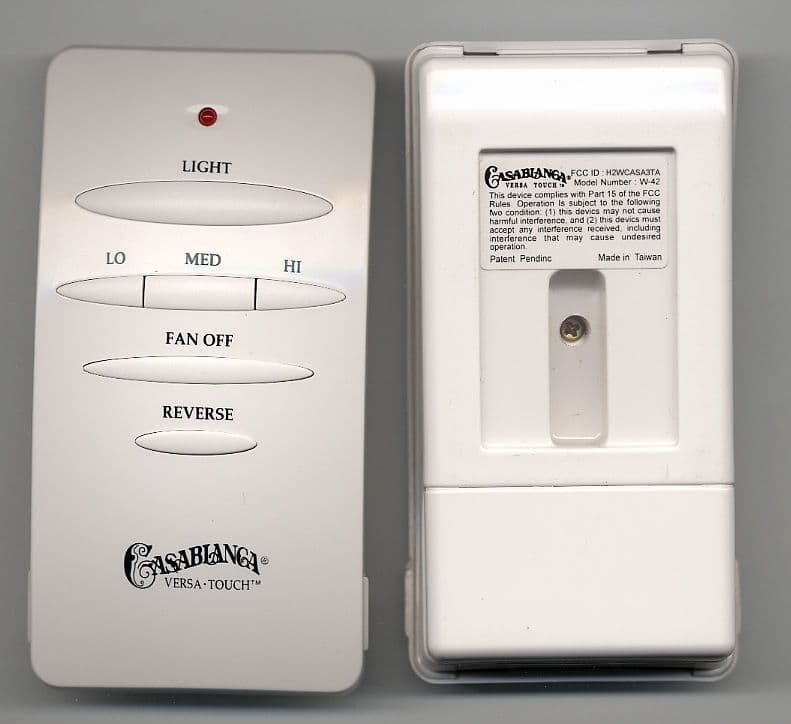
H2WCASA3TA
Jun 10, 2001Ceiling fan and lamp remote control.
Equipment Class
DSC - Part 15 Security/Remote Control Transmitter