H2WCASA12TRemote control for ceiling fan
Hunter Fan Company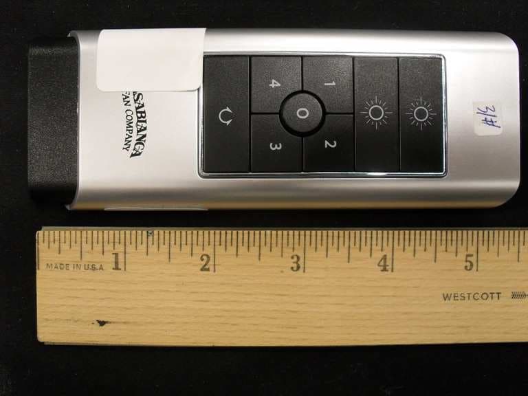
Click to zoom
Application Details
- Equipment Class
- DSR - Part 15 Remote Control/Security Device Transceiver
- Date of Grant
- Nov 28, 2010
- Application Purpose
- Original Equipment
- Date of Application
- Nov 28, 2010
- Equipment Note
- Remote control for ceiling fan
- Frequency Range
- 303.50000000 - 303.50000000
- Company
- Hunter Fan Company
- Country
- United States
Documents & Files
Document Text
Text extracted from the exhibit documents filed with the FCC. Open a document above to read the original.
Users Manual
W-75 WALL CONTROL W-75SL Operates Downlights ONLY W-75DL Operates Up and Downlights BATTERY INSTALLATION Open Battery Door by pressing down on the insert tab provided. Install a “MN21/A23” 12v alkaline batterie in the space provided. Please observe proper polarity placement. Replace Battery Door. Battery Door 12V CHANGING FREQUENCY SETTING You will only have to change the dip switch settings in the remote if you are using more than one fan in the same area and want to control them separately. DIP SWITCHES SET TO ‘111111’ (Factory Setting) NOTE: DO NOT set dip switch setting in the remote to ‘000000’, this may cause frequency interference from other Casablanca Products.All fans leave the factory set to “111111” (Figure 2) (Figure 1) 12V DIP SWITCHES SET TO ‘000000’ To change frequency: 1. Turn power OFF at the circuit breaker or fuse box and at the wall switch, for the fan you want to change. 2. Open the battery door and remove the battery as shown in Figure #1 3. Change the dip switch settings, assuring that they are match the Direct-Touch wall control. See Figure #2. 4. Re-install the battery with the proper polarity position and the battery door. 5. At the circuit breaker or fuse box and at the wall switch, turn the power on for the fan whose frequency you are changing. 6. Within 20 seconds of restoring power to the ceiling fan press and hold both the “1” and reverse buttons as shown in Figure #3. For 3 seconds, you will hear an audible tone indicating the command has been accepted. The Fan and Lights will be off. The frequency is now changed. OPERATION SPEED CONTROL There are five individual speed settings for the fan. Each speed is indicated by the number on the controller and an audible tone for each speed. To select the desired fan speed: Press the number on the controller corresponding to the speed desired. 4 is high, 3 medium, 2 low, 1 ultra-low, and 0 is off. Note: It is normal for the fan to start in the "High" position from "Off" before changing to the selected speed. OPERATION REVERSING AIRFLOW The direction of airflow can be changed from downward to upward or from upward to downward. To reverse the airflow: 1. Make sure the fan is on and blades are turning. 2. Press the reverse button. You will hear a series of clicks from the fan as it speeds up before coming to a stop and changing direction. OPERATION LIGHTS To turn the lights off and on, press and release the button for either the up or down lights for less than one second. To dim either the up or down light, Press and hold the button for either the up or down light for more than 1 second. The light will come on at the last brightness setting and increase in brightness until full power is reached, then start dimming until the lowest setting is reached. This cycle will repeat until you release the light button. Up Light Down Light Note: The dimming feature will only work as long as the dimming feature remains active. See "Operation CFL mode". Your fan has the ability to disable the dimming feature to allow the use of CFL bulbs. To activate CFL mode: 1. Turn the fan off by using your wall switch. 2. Allow the fan to remain off for at least 5 seconds. 3. Turn the fan on by using your wall switch. 4. Immediately press and hold the "1" and "3" buttons for at least 5 seconds. The fans lights will go to 100% brightness and the dimming function will be disabled. To cancel CFL mode: 5. Turn the fan off by using your wall switch. Allow the fan to remain off for at least 5 seconds. 6. Turn the fan on by using your wall switch. 7. Immediately press and hold the "2" and "4" buttons for at least 5 seconds. The fans lights will dim to 50% brightness and the dimming function will be enabled. Press and hold the light buttons until the desired dimmer setting is reached. Caution: CFL bulbs will not function properly when dimmed, which may result in flickering or reduced bulb life. OPERATION CFL MODE AUTOMATIC DEMONSTRATION PROGRAM Programmed into every Direct-Touch fan is an Automatic Demonstration Program. It can be used to fully demonstrate and test the operation of the fan. To enter the demonstration program: 1. Turn the fan off for at least 5 seconds by using your wall switch. This will clear the fan memory ready for programming. 2. Turn the fan on by using your wall switch. 3. Immediately hold the "0" button for at least 5 seconds. A multi-tone signal will verify the start of the test program. The fan and lights will go through a series of changing fan speeds, reversing the fan operation mode, turning off/on, and dimming the lights. The complete cycle lasts slightly over one minute. It will continue to repeat until the wall switch is turned off for more than five seconds, cancelling the program. Note: With CFL mode active, the lights will not dim. OPERATION SAFE-EXIT® The Safe-Exit Program gives you about thirty seconds of light when you turn the lights off, enabling you to exit your home before the lights go out. To enter the Safe-Exit Program: 1. Turn the fan off by using your wall switch. Allow the fan to remain off for at least 5 seconds. 2. Turn the Power on. Immediately press and hold the "4" button for 5 seconds. When a light button is pressed, an audio tone and series of lights blinking will indicate the program is active. 3. With CFL mode disabled, Pressing a Light Button will cause the lights to stay on at 50% brightness for 20 seconds then decrease in intensity for 30 seconds then turn off. 4. With CFL mode active, Pressing a Light Button will turn the lights off after 30 seconds. 5. To cancel the Safe-Exit Program, turn off power off using your wall switch and leave off for five seconds. Safe-Exit The Light-Minder Program automatically turns OFF the fan mounted lights after two hours. To enter the Light-Minder Program: 1. To operate the lights for Light Minder Program Turn the fan off by using your wall switch. Allow the fan to remain off for at least 5 seconds. 2. Turn the Power on. Immediately press and hold the "1" butto…
Text truncated - open the document above for the full version.
Block Diagram
LTR C BACD 6 5 4 3 2 1 DATE: DBA ECO NO: APPROVED: REVISION RECORD SCALE: SHEET: OF DRAWING NO: TITLE:COMPANY: RELEASED: DATED: DATED: QUALITY CONTROL:CHECKED: DATED: DATED: DRAWN: CODE: SIZE: REV: 1 1 B Logic HOEY Steven Tang 08/JULY/2010 08/JULY/2010 Block Drawing TX HUND751 S3F9454 Microcontroller RF Circuit DIP SW for ID Select Key Input Circuit 3.3V Regulator X2 303.5MHZ X1 4MHz B1 GP 23AE 12V
Operational Description
2010-9-22 Operational description of HUND751.doc Page 1 of 2 1 Operation Description of HUND751/HUNS751 Hand Held Control (HUND751/HUNS751) is Fan & Light control and compatibility with Wall Control. Design requirements 1. Hand Held Control using a 12V/GP23AE battery。 2. Design 8DIP SW,6DIP of those are used for customer,but 2 DIP of those are design retaining. 3. Have CFL choice function and address code study function. 4. Light Fan minder, safe Exit and home safe model. 5. TX frequency 303.5M HX ,Remote range >18M. A. Key function. I. Light function: 1. First press/release of the up light button – up lights shall turn ON. 2. Second press/release of the up light button - up lights shall turn OFF. 3. First press/release of the Down light button – Down lights shall turn ON. 4. Second press/release of the Down light button - Down lights shall turn OFF. 5. Press and hold the up or down light button. After 1 second up or down light shall dimming or become brighter. Release the Light button when the desired brightness is reached. II. Fan function: 1. Press/release of the “1” button, - a tones from the Piezo Buzzer and the fan shall be turn to lowest speed. 2. Press/release of the “2” button, - a tones from the Piezo Buzzer and the fan shall be turn to two speed. 3. Press/release of the “3 button, - a tones from the Piezo Buzzer and the fan shall be turn to three speed. 4. Press/release of the “4” button, - a tones from the Piezo Buzzer and the fan shall be turn to maximal speed. 4. Press/release of the “0” button, - a tones from the Piezo Buzzer and the fan shall be turn to OFF. 5. Press/release of the “Rev” button, - a tone from the Piezo Buzzer and the fan shall be reverse. 2010-9-22 Operational description of HUND751.doc Page 2 of 2 2 B. Setting access ID Channels 1. Turn the power OFF. 2. Change the DIP switch (SW1) settings. 3. Within 20 seconds of restoring power and the RF Wall Control push the “FAN” and “REVERSE” buttons until a tone from the piezo-buzzer is produced as an audible confirmation. Release the buttons and the Fan & Lights shall be OFF. 4. Once completed the ID test, must change the TX and RX 6bit ID to default “ON”.
Schematics
LTR C BACD 6 5 4 3 2 1 DATE: DBA ECO NO: APPROVED: REVISION RECORD SCALE: SHEET: OF DRAWING NO: TITLE:COMPANY: RELEASED: DATED: DATED: QUALITY CONTROL:CHECKED: DATED: DATED: DRAWN: CODE: SIZE: REV: 1 1 Logic Output HOEY Steven Tang 08/JULY/2010 08/JULY/2010 W75DL 01 COMPUTIME A4 Fan1 S3F9454 1 VSS 2 P1.0 3 P1.1 4 P1.2 5 P2.0 6 P2.1 7 P2.2 8 P2.3 9 P2.4 10 P2.5 20 VDD 19 P0.0 18 P0.1 17 P0.2 16 P0.3 15 P0.4 14 P0.5 13 P0.6 12 P0.7 11 P2.6 U3 Fan2 Fan3 3 1 2 X1 4MHz C7 0.1uf R2 100k R5 100k 15236 7 4 8 9 10 11 12 S2 RECODE_12P Fan4 Reverse Uplight Downlight Fan Off D3 D4 J1 J2 R8 10k C12 0.1uf Q3 CZ-3.3V + C1 10UF BATTERY 12V BLK1 +3.3V +3.3V RF_OUTPUT +3.3V V4 W75DLTRANSMITTER 5 4 3 AB C B Computime A SCALE: SHEET: OF DRAWING NO: TITLE:COMPANY: RELEASED: DATED: DATED: QUALITY CONTROL:CHECKED: DATED: DATED: DRAWN: CODE: SIZE: REV: 1 1 B C 2 1 DATE: LTR ECO NO: APPROVED: REVISION RECORD PT4450 HUN32RF C9 (PF) C6(PF) URU AT Remote 4.7 27 5 200 R3 (ohm) 330 1.2K C7(PF) 1 NOT USE C4 200PF200PF 18NH W74DL 4.7 27 470 1 24/Sep/10 Steven TANG HOEY 33PF W75DL 4.7 10PF 390 1 24/Sep/10 C5 5PF5PF 5PF 2.2PF ITEM Model 1 OSCOUT 2 GND 3 PAOUT 6 OSCIN 5 VDD 4 CE U1 Y1 303.5MHZ L1 220NH L2 27NH C1 0.1UF C2 47PF C3 47PF C4 33PF C52.2PF C610PF C71PF C81PF R1 10K R2 NOT USE R3 390R 1 DATA 2 VDD 3 GND P1 C9 4.7PF VDD
Test Report
Client: Product Designation: Transmitter Model W75SL/W75DL Report Number: 100220173ATL-001 All services undertaken are subject to the following general policy: This report is for the exclusive use of Intertek's Client and is provided pursuant to the agreement between Intertek and its Client. Intertek's responsibility and liability are limited to the terms and conditions of the agreement. Intertek assumes no liability to any party, other than to the Client in accordance with the agreement, for any loss, expense or damage occasioned by the use of this report. Only the Client is authorized to copy or distribute this report and then only in its entirety. Any use of the Intertek name or one of its marks for the sale or advertisement of the tested material, product or service must first be approved in writing by Intertek. The observations and test results in this report are relevant only to the sample tested. This report by itself does not imply that the material, product, or service is or has ever been under an Intertek certification program. This report must not be used to claim product endorsement by A2LA, NIST, or any agency of the US Government. Tested by: Tests performed by:Report reviewed by: Standard: Richard C. Bianco EMC Project Engineer Troy J. Ihle EMC Project Engineer Hunter Fan 7130 Goodlett Farms Pkwy Suite 400 Memphis, TN 38016 Contact: Robert Davis Phone: 901.248.2212 TEST REPORT September 30, 2010 Intertek Testing Services NA Inc. 1950 Evergreen Blvd., Suite 100 Duluth, GA 30096 47 CFR Part 15, Subpart C (15.231 - Periodic operation in the band 40.66- 40.70 MHz and above 70 MHz) RSS-210, Issue 7, 2007 Page 1 of 20EMC Report for Hunter Fan on the Transmitter Model W75SL/W75DL 09/30/2010Report Number: 100220173ATL-001Issued: Intertek 2.0 Test Summary 1.0 Introduction and Conclusion Test DateTest Full NameResultSection Overview of EUT (Low Power Transmitters) (FCC 15C - EUT Overview)4.0 09/29/2010Restrictions (FCC 15C - 15.231(a))PASS5.0 09/29/2010Duty Cycle Determination (FCC 15A - 15.35(c))PASS6.0 09/29/2010Radiated Emissions (FCC 15C - 15.231(b))PASS7.0 09/29/2010Bandwidth Requirements (FCC 15C - 15.231(c))PASS8.0 Conducted emissions on AC power lines (Conducted Emissions) was waived due to is a battery operated device.NA Conducted Emissions for Intentional Radiators (FCC 15C - 15.207) was waived due to is a battery operated device.NA The tests indicated in section 2.0 were performed on the product constructed as described in section 3.0. The remaining test sections are the verbatum text from the actual data sheets used during the investigation. These test sections include the test name, the specified test Method, a list of the actual Test Equipment Used, documentation Photos, Results and raw Data. No additions, deviations, or exclusions have been made from the standard(s) unless specifically noted. Based on the results of our investigation, we have concluded the product tested complies with the requirements of the standard(s) indicated. The results obtained in this test report pertain only to the item(s) tested. Page 2 of 20EMC Report for Hunter Fan on the Transmitter Model W75SL/W75DL 09/30/2010Report Number: 100220173ATL-001Issued: Intertek 3.0 Description of Equipment Under Test Eq uip me nt Unde r T est Description Manu fac ture r Mo del N umbe r Serial Nu mb er Fan/Light remote control Hunter Fan W75SL/W75DL 8 & 49 EUT receive date: 09/29/2010 EUT receive condition: Good Description of EUT provided by Client: The W75SL/W75DL are remote controls for a lighted ceiling fan. Description of EUT exercising: The remote control was powered with a new battery and placed in a rapid transmit mode with normal modulation. Page 3 of 20EMC Report for Hunter Fan on the Transmitter Model W75SL/W75DL 09/30/2010Report Number: 100220173ATL-001Issued: Intertek Overview of EUT (Low Power Transmitters) (FCC 15C - EUT Overview)4.0 Method: Complete the overview spreadsheet. Related Submittal(s) Grants: This report is for use with an application for certification of a low power transmitter. One transmitter is included in the application. Hunter Fan 7130 Go o d lett Farms Pkwy Ste. 400 M emph is TN 38016 Trade Name & Model No. W 75SL/W 75DL FCC Identifier H2WCASA12T Frequency Range (MHz) 303 A nten na Typ e (15.203) In ternal Hunter Fan 7130 Go o d lett Farms Pkwy Ste. 400 M emph is TN 38016 Additions, deviations and exclusions from standards None This report is for use with an application for certification of a low power transmitter. One transmitter is included in the application. Applicant Manufacturer name & address Related Submittals and Grants: Data: Page 4 of 20EMC Report for Hunter Fan on the Transmitter Model W75SL/W75DL 09/30/2010Report Number: 100220173ATL-001Issued: Intertek Restrictions (FCC 15C - 15.231(a))5.0 Method: 15.231(a) The provisions of this section are restricted to periodic operation within the band 40.66-40.70 MHz and above 70 MHz. Except as shown in paragraph (e) of this section, the intentional radiator is restricted to the transmission of a control signal such as those used with alarm systems, door openers, remote switches, etc. Continuous transmissions, voice, video and the radio control of toys are not permitted. Data is permitted to be sent with a control signal. The following conditions shall be met to comply with the provisions for this periodic operation: (1) A manually operated transmitter shall employ a switch that will automatically deactivate the transmitter within not more than 5 seconds of being released. (2) A transmitter activated automatically shall cease transmission within 5 seconds after activation. (3) Periodic transmissions at regular predetermined intervals are not permitted. However, polling or supervision transmissions, including data, to determine system integrity of transmitters used in security or safety applications are allowed if the total duration of transmissions does not exceed more than two seconds per hour for each transmitter. There is…
Text truncated - open the document above for the full version.
Test Setup Photos
09/30/2010Report Number: 100220173ATL-001Issued: Intertek Radiated Emissions (FCC 15C - 15.231(b))7.0 Test setup - front view Page 13 of 20 EMC Report for Hunter Fan on the Transmitter Model W75SL/W75DL 09/30/2010Report Number: 100220173ATL-001Issued: Intertek Radiated Emissions (FCC 15C - 15.231(b))7.0 Test setup - rear view Photo: Plot: Page 14 of 20EMC Report for Hunter Fan on the Transmitter Model W75SL/W75DL
Contact Information
Applicant
Julian A Martin(Compliance Manager)
Test Firm
Intertek Testing Services NA Inc.Charles Parker
Technical Specifications
| # | Rule Parts | Frequency Range | Power Output |
|---|---|---|---|
| 1 | 15.231 | 303.5 MHz - 303.5 MHz | - |
Other Applications from Hunter Fan Company

H2WCASA11T
Jan 19, 2010Remote control for ceiling fan
Equipment Class
DSC - Part 15 Security/Remote Control Transmitter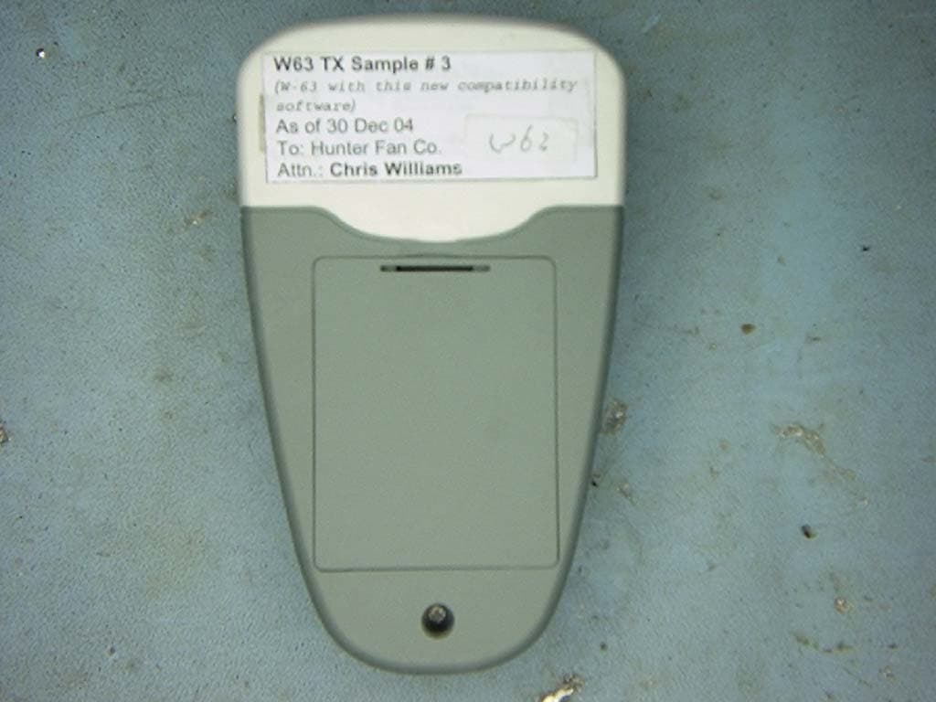
H2WCASA7T
Jul 19, 2005Fan and Light Control Transmitter
Equipment Class
DSC - Part 15 Security/Remote Control Transmitter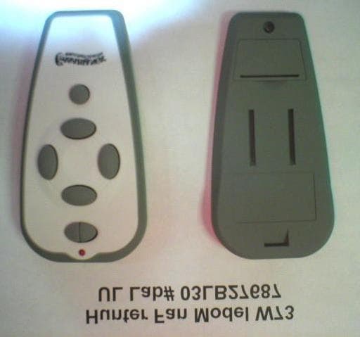
H2WCASA8T
Jun 17, 2004Ceiling fan remote control transmitter
Equipment Class
DSC - Part 15 Security/Remote Control Transmitter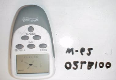
H2WCASA6T
Mar 28, 2002Ceiling fan and lamp remote contro.
Equipment Class
DSC - Part 15 Security/Remote Control Transmitter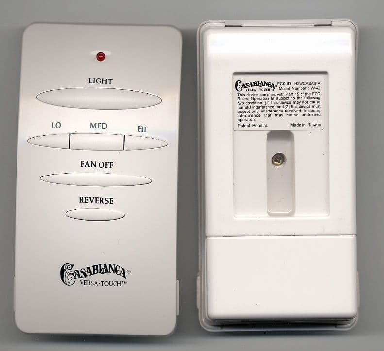
H2WCASA3TA
Jun 10, 2001Ceiling fan and lamp remote control.
Equipment Class
DSC - Part 15 Security/Remote Control Transmitter