H2WCASA8TCeiling fan remote control transmitter
Hunter Fan Company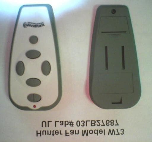
Click to zoom
Application Details
- Equipment Class
- DSC - Part 15 Security/Remote Control Transmitter
- Date of Grant
- Jun 17, 2004
- Application Purpose
- Original Equipment
- Date of Application
- Jun 17, 2004
- Equipment Note
- Ceiling fan remote control transmitter
- Frequency Range
- 303.50000000 - 303.50000000
- Company
- Hunter Fan Company
- Country
- United States
Documents & Files
Document Text
Text extracted from the exhibit documents filed with the FCC. Open a document above to read the original.
Users Manual
1©2003 Casablanca Fan Co. www.CasablancaFanCo.com SCREW 6-32 X 1” (2) SCREW 6-32 X 3 /8” (2) WOOD SCREW 1” (2) DRYWALL ANCHOR 6-32 (2) 12V BATTERY W-72 CONTROL W-72 CONTROL HOLDER VERSA•TOUCH 2 ♦ INSTALLATION VERSA•TOUCH 2 ♦ CONTROL BRACKET INSTALLATION Standard Light Switch Step A. Remove the two screws holding the switch cover plate. Do not remove the cover plate. Step B. Orient the control bracket as shown and line up the two inner mounting holes with those on the switch. Step C. Install and tighten screws by hand only. INNER MOUNTING HOLES CONTROL BRACKET STANDARD TOGGLE SWITCH SWITCH COVER PLATE Rocker Light Switch Step A. Break off the two tabs by pushing outward. Step B. Remove the two screws holding the switch cover plate. Do not remove the cover plate. Step C. Orient the control bracket as shown and line up the two inner mounting holes with those on the switch. Step D. Install and tighten screws by hand only. OUTER MOUNTING HOLES CONTROL BRACKET ROCKER TYPE LIGHT SWITCH SWITCH COVER PLATE Wall Installation Step A. Locate a 2x4 wall stud in a convenient location. Step B. Orient the control bracket as shown over the 2x4 stud. Step C. Use the 1” wood screws in either the inner or outer mounting holes. Install and tighten screws by hand only. DECOR OVALHEAD SCREW 6-32 X 1” ANCHOR PANHEAD SCREW WOOD SCREW 1” DRYWALL ANCHOR Note: The wall anchors and 6-32 x 1” screws may be used in situations where mounting to a stud is not pos- sible. Use the inner mounting holes. After securing the anchor, discard the anchor’s pointed screws and use the 6-32 decor ovalhead screws supplied. CAUTION! Do not use with wall dimmer. 2 Changes or modifications not expressly ap- proved in writing by Casablanca Fan Co. may void the user’s authority to operate this equipment. This device complies with RSS-210 of Industry Canada. Operation is subject to the following two conditions: (1) this device may not cause interference, and (2) this device must accept any interference, including interference that may cause undesired operation of the device. PN: 8943420 Rev.A PD: JAN03PDG 2©2003 Casablanca Fan Co. www.CasablancaFanCo.com SEND SIGNAL LED VERSA•TOUCH 2 OPERATION Fan Control To start the fan. Press the selected speed button to run the fan at the desired speed. LO=Low speed MED=Medium speed HI=High speed To turn off the fan. Press the FAN OFF button. Airflow Direction To reverse the airflow press the REVERSE button. Reverse operates at any speed whether fan is on or off. The fan returns to its set speed after reversing. Light Control Turn the light on or off independently from the fan by pressing the LIGHT button. Keep pressing the button in excess of 0.7 seconds, it becomes a dimmer. The light varies from ‘bright’ to ‘dim’ over approximately 8 seconds. This sequence will reverse the light when it reaches the brightest or dimmest level if you continue to hold the LIGHT button. Release the button when the desired level is reached. Auto Resume Quick (pressing less than 0.7 seconds) on/off operation of the LIGHT button maintains the desired brightness level set previously. 9 VERSA•TOUCH 2 ♦ IF FAN DOES NOT WORK If the fan is not functioning after installation: Step 1. Check to make sure that batteries are installed correctly in the control. Step 2. Turn the power off to the fan (from the circuit breaker) for at least 5 seconds. Step 3. Turn the power back on (at the circuit breaker) and push the Hi, Med, and Low buttons–in that order–within 20 seconds. Step 4. The fan should now function properly. VERSA•TOUCH 2 ♦ CHANGING FREQUENCY SETTING You will only have to change the dip switch settings in the remote if you are using more than one fan in the same area and want to control them separately. Step 1. At the circuit breaker or fuse box, turn the power off for the fan you want to change. Step 2. Open the battery door of the Versa•Touch control and remove the batteries. Step 3. Change the dip switch settings, assuring that they are different from the previously installed Versa•Touch fan. Step 4. Re-install the batteries and the battery door on the control. Step 5. At the circuit breaker or fuse box, turn the power back on for the fan whose frequency you are changing. Step 6. Within 20 seconds of restoring power, push the Hi, Med, and Lo buttons (in that order). Note: All fans leave the factory set to ‘00000’. WITHIN 20 SECONDS OF TURNING THE FAN ON, PRESS IN THIS ORDER TO SET NEW FREQUENCY: 1. HI 2. MED 3. LO 1 2 3 CIRCUIT BREAKER OR FUSE BOX PRESS IN THIS ORDER TO SET NEW FREQUENCY: 1. HI 2. MED 3. LO DIP SWITCH SET TO ‘01001’ DIP SWITCH SET TO ‘10000’ VERSA•TOUCH 2 CONTROL (BACK) Note: You may want to label your controls to assure you do not mix them up. WARNING: Do not turn the power off at the circuit breaker, then back on, for the previously installed Versa•Touch 2 fan(s), as you may inadvertantly change the frequency set- tings for it as well. LO MED HI LIGHT FAN STOP REVERSE 1 2 3 2 3©2003 Casablanca Fan Co. www.CasablancaFanCo.com Before Requesting Service: Please follow this troubleshooting guide before contacting your dealer for assistance. PROBLEM POSSIBLE REMEDIES PROBLEMPOSSIBLE REMEDIES.. FAN WILL NOT START•Check main circuit fuses, circuit breakers, or wall switch position. Check all wire connections, making sure the power is turned off during this inspection. •Pin connectors are not making good contact. Check the connections in the switch housing and under the top cover. •Battery weak - install fresh battery. •Fan receiver defective - replace. •Check the frequency setting: Turn power off, at the circuit breaker, only for the fan not functioning for at least 5 seconds; turn the power back on; within 20 seconds press the Hi, Med, and Lo buttons (in that order) to set the frequency of the fan to the control. FAN WOBBLES OR SHAKES•Be sure canopy pin is properly set into the slot on the ball. EXCESSIVELY•Check that bladeholders have not been bent during installation and blades are balanced. •Hanger brack…
Text truncated - open the document above for the full version.
External Photos
Hunter (Casablanca) Fan W73 Transmitter - External View Front Rear Note: W72 is identical, except that a single button appears just below the LED, rather than the “split” button shown.
ID Label/Location Info
VERSA•TOUCH™ Part Numbers 7801890 / 7854200 FCC ID : H2WCASA8T IC ID : 3558-CASA8T Made in China 060 Pomona, CA 91768 W72: Label size: 39 x 22 mm
ID Label/Location Info
VERSA•TOUCH™ Part Numbers 7801900 / 7854210 FCC ID : H2WCASA8T IC ID : 3558-CASA8T Made in China 060 Pomona, CA 91768 W73: Label size: 39 x 22 mm
Internal Photos
Hunter (Casablanca) Fan W73 Transmitter - Internal View Component/Solder Side of Circuit Board Antenna Side Hunter (Casablanca) Fan W73 Transmitter - Internal View Component/Solder side Close up Hunter (Casablanca) Fan W73 Transmitter - Internal View Antenna Side - Close up
Operational Description
FCC ID: H2WCASA8T IC:3558-CASA8T Fan & Light Remote Control Transmitter Operational Description Description: This low powered transmitter operates by sending a pulse modulated signal to a corresponding receiver to control a ceiling fan power (off/low/med/high/direction) and lamp (off/low/med/high). The carrier frequency of 303.5 MHz is pulse modulated with a repeating sequence of short or long pulses that represents the desired function and the user-selectable security code. Transmission ceases upon release of the button. The transmitter contains an integrated antenna that is not detachable or adjustable by the user. The transmit frequency is also fixed and not adjustable by the user. Transmit sequence: The transmit sequence begins when a button is depressed. The encoder chip is powered and the depressed button and security code is inputted to the chip. The encoder chip outputs the timed sequence of pulses to a SAW resonator circuit which turns the RF carrier on and off in the required timing pattern. The SAW resonator circuit maintains a very stable operating frequency. Pulse timing: The pulse timing pattern and duty cycle was measured and is detailed in the accompanying EMC test report.
Test Report
Project: 03RT8964 File: MC1324 Report: 030311A (Revised June 7, 2004) Date: September 30, 2003 Model: W72 and W73 Ceiling Fan RF Remote Test Report On Electromagnetic Compatibility Testing Hunter Fan Co Memphis, TN USA Copyright 2003 Underwriters Laboratories Inc. Underwriters Laboratories Inc. authorizes the above-named company to reproduce this Report provided it is reproduced in its entirety. Project: 03RT8964 Underwriters Laboratories, Inc. Issued: 09/30/03 File: MC1324 Test Report on Electromagnetic Compatibility Page 2 of 34 FCC ID: H2WCASA8T Test Report: 030311A IC: 3558-CASA8T Test Report Details: Tests Performed By: Underwriters Laboratories Inc. 12 Laboratory Drive Research Triangle Park, NC 27709 Tests Performed For: Hunter Fan Co 2500 Frisco Avenue Memphis, TN 38114 USA Applicant Contact: Mr. Robert Davis Safety and Test Engineer - International (901) 248-2212 (901) 248-2382 - Fax Test Report Number: 030311A Test Report Date: September 30, 2003 (Revised June 7, 2004) Product Type: Ceiling Fan RF Remote Model Number: W72 and W73 Sample Serial Number: unserialized, pre-production sample Sample Tag Number: S03LB27687 EUT Category: Transmitter - Low Powered EUT Type: Hand Held Sample Receive Date: September 25, 2003 Testing Start Date: September 25, 2003 Date Testing Complete: September 29, 2003 Underwriters Laboratories Inc. reports apply only to the specific samples tested under stated test conditions. All samples tested were in good operating condition throughout the entire test program. It is the manufacturer's responsibility to assure that additional production units of this model are manufactured with identical electrical and mechanical components. Underwriters Laboratories Inc. shall have no liability for any deductions, inferences or generalizations drawn by the client or others from Underwriters Laboratories Inc. issued reports. This report shall not be used to claim, constitute or imply product certification, approval, or endorsement by NVLAP, A2LA, or any agency of the US government. This report may contain test results that are not covered by the NVLAP or A2LA accreditation. The scope of accreditation is limited to the specific tests that are listed on the NVLAP and/or A2LA certificates provided at the end of this report. Comments or complaints regarding the content of this report may be brought to the attention of the report’s author. Project: 03RT8964 Underwriters Laboratories, Inc. Issued: 09/30/03 File: MC1324 Test Report on Electromagnetic Compatibility Page 3 of 34 FCC ID: H2WCASA8T Test Report: 030311A IC: 3558-CASA8T Summary of Testing: Test Test Name Comply Does Not See # Test Requirement/Specification Comply Remark 1 Radiated Disturbance Emissions - 30 MHz to 3.2 GHz X - 47 CFR Part 15, Subpart C / 47 CFR Part 15, Subpart C, Section 15.209 and 15.231 2 Radiated Disturbance Emissions - Peak-to-Average Ratio N/A N/A 47 CFR Part 15, Subpart C / 47 CFR Part 15, Subpart C, Section 15.231 3 Radiated Disturbance Emissions - Occupied Bandwidth X - 47 CFR Part 15, Subpart C / 47 CFR Part 15, Subpart C, Section 15.231 4 Radiated Disturbance Emissions - Restricted Bands X - 47 CFR Part 15, Subpart C / 47 CFR Part 15, Subpart C, Section 15.205 Remarks: 1) All tests are considered applicable to Canadian requirements as detailed in RSS-210. Emissions test site is registered by Industry Canada as IC-2953. 2) This device is a manually operated device. Device was observed to cease transmission immediately upon release of buttons. The word “immediately” represents no noticeable delay as observed with the human eye and can be considered no more than 200 ms. This complies with the 5 second maximum turn-off requirement. 3) Device contains an integrated antenna. This antenna is not detachable. 4) Per FCC Part 2.1093(c) this device is considered exempt from routine environmental evaluation for RF exposure. 5) The following modifications were determined to be required to comply: a. R1 = 270 Ω b. R2 = 510 Ω c. R3 = 91 kΩ d. C2 = 10 pF e. C3 = 1.8 pF 6) Emissions Designator for Canada is L1D508k. Report Revisions: June 7, 2004 - Revised to correct sample received date. Revised to state that cease transmission time characterized as “immediately” complies with requirement of less than five seconds. Conclusion: The tests listed in the Summary of Testing section of this report have been performed and the results recorded by Underwriters Laboratories Inc. in accordance with the procedures stated in each test requirement and specification. The test list was determined by the Applicant as being applicable to the Equipment Under Test. As a result, the subject product has been verified to comply or not comply as noted in the Summary of Testing with each test specification. The test results relate only to the items tested. Prepared By: Reviewed By: Jim Marley Mark Nolting NARTE Certified EMC Engineer NARTE Certified EMC Test Lab Engineer EMC-002278-NE ATL-0340-E (919) 549-1408 (919) 549-1584 Project: 03RT8964 Underwriters Laboratories, Inc. Issued: 09/30/03 File: MC1324 Test Report on Electromagnetic Compatibility Page 4 of 34 FCC ID: H2WCASA8T Test Report: 030311A IC: 3558-CASA8T Test Facilities: Test Location A) 10-Meter Anechoic Chamber (pIndustry Canada - IC 2953, NVLAP - 200246-0, VCCI - R-722) Constructed by Lindgren RF Enclosures, this room consists of a 17.9 by 12 by 8.3 m (inside clearance) shielded room lined with TDK absorber material. The walls, floor (conducting ground plane) and ceiling are constructed of double sided galvanized sheet steel supported by 19 mm thick particle board. The interior walls and ceiling are covered with 10 by 10 cm, 4.6 mm thick ferrite tiles and partially covered with polystyrene absorber cones. Removable floor tiles and cones covering the floor between the EUT and antenna are provided when RF immunity testing is performed. Room is provided with a 4.0 m diameter embedded turntable and a 1.2 by 2.1 m and 2.4 by 2.4 m double knife edge doors for access. …
Text truncated - open the document above for the full version.
Test Setup Photos
Project: 03RT8964 Underwriters Laboratories, Inc. Issued: 09/30/03 File: MC1324 Test Report on Electromagnetic Compatibility Page 19 of 34 FCC ID: H2WCASA8T Test Report: 030311 IC: 3558-CASA8T Test 1, Test Set-Up Photo: Radiated Disturbance Emissions - 30 MHz to 1000 MHz
Contact Information
Applicant
Julian A Martin(Compliance Manager)
Technical Contact
Hunter Fan CompanyRobert Davis
[email protected]901-248-2212
2500 Frisco Ave. · Memphis, Tennessee · United States
Non-Technical Contact
Hunter Fan CompanyRobert Davis
[email protected]901-248-2212
Test Firm
UL LLCRick Titus
Technical Specifications
| # | Rule Parts | Frequency Range | Power Output |
|---|---|---|---|
| 1 | 15.231 | 303.5 MHz - 303.5 MHz | - |
Other Applications from Hunter Fan Company
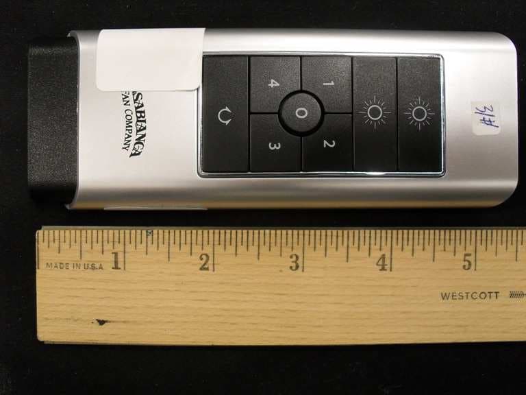
H2WCASA12T
Nov 28, 2010Remote control for ceiling fan
Equipment Class
DSR - Part 15 Remote Control/Security Device Transceiver
H2WCASA11T
Jan 19, 2010Remote control for ceiling fan
Equipment Class
DSC - Part 15 Security/Remote Control Transmitter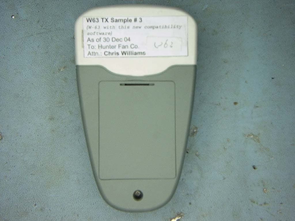
H2WCASA7T
Jul 19, 2005Fan and Light Control Transmitter
Equipment Class
DSC - Part 15 Security/Remote Control Transmitter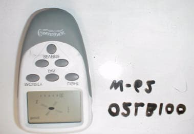
H2WCASA6T
Mar 28, 2002Ceiling fan and lamp remote contro.
Equipment Class
DSC - Part 15 Security/Remote Control Transmitter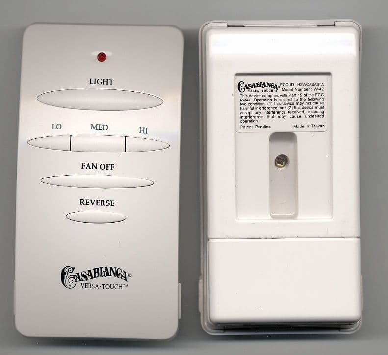
H2WCASA3TA
Jun 10, 2001Ceiling fan and lamp remote control.
Equipment Class
DSC - Part 15 Security/Remote Control Transmitter