H78KPBSRU100D10 WATT UHF RF MODEM
KP Electronic Systems Ltd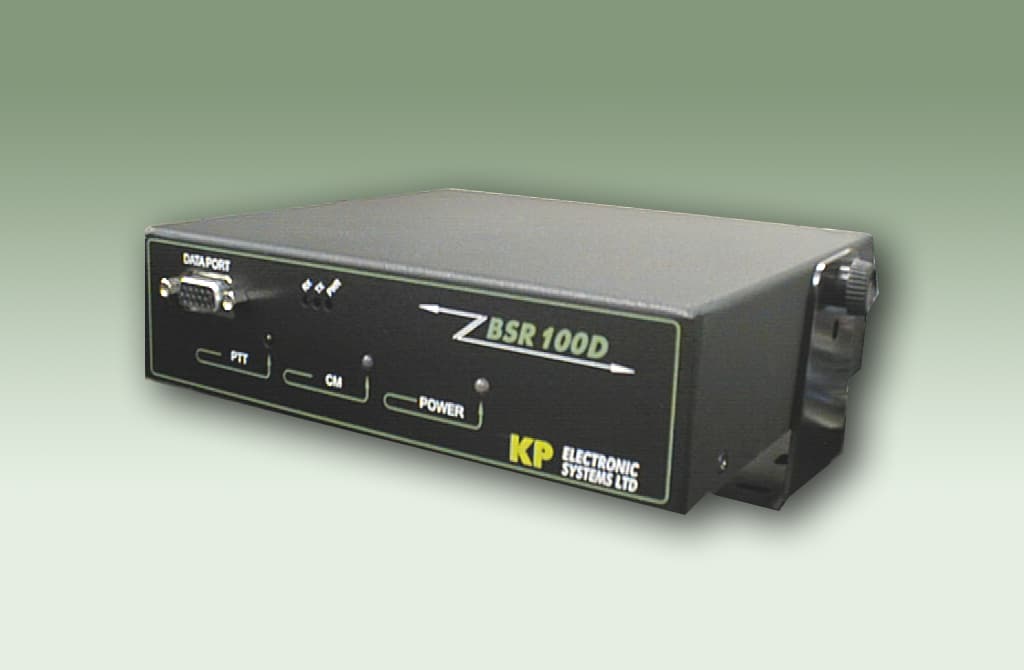
Click to zoom
Application Details
- Equipment Class
- TNB - Licensed Non-Broadcast Station Transmitter
- Date of Grant
- Mar 18, 2007
- Application Purpose
- Original Equipment
- Date of Application
- Mar 11, 2007
- Equipment Note
- 10 WATT UHF RF MODEM
- Frequency Range
- 450.00000000 - 470.00000000
- Company
- KP Electronic Systems Ltd
- Country
- Israel
Documents & Files
Document Text
Text extracted from the exhibit documents filed with the FCC. Open a document above to read the original.
Users Manual
ISRAEL Office: Email: [email protected] P.O. Box 42, Tefen Industrial Park, Tefen 24959 Tel: 972-4-987-3066 / Fax: 972-4-987-3692 USA Office: KP ELECTRONICS INC. Email: [email protected] 109 Tudor Drive, North Wales, PA 19454 Tel: (215) 542-7460 / Fax: (215) 542-7461 Web Site: www.kpsystems.com P.N: Book 087 Rev: New Approved: Moshe Z. 22/05/03 BSR100D™ Wireless VHF / UHF Radio Modem User Manual BSR100D™ Wireless Radio Modem Page 2 User Manual Table of Contents 1 GENERAL DESCRIPTION............................................................................................4 1.1 BSR100D FUNCTIONS ............................................................................................... 4 1.2 F RONT PANEL DISPLAY ............................................................................................. 4 1.3 R EAR PANEL DISPLAY ............................................................................................... 5 2 RADIO MODULE DESCRIPTION .............................................................................6 3 MODEM MODULE DESCRIPTION..........................................................................7 3.1 DATA PORT INTERFACE ............................................................................................7 4 PREPARING FOR OPERATION..............................................................................10 4.1 RF EXPOSURE STATEMENT .......................................................................................1 0 4.2 C ONNECTING ASSEMBLY CABLES .......................................................................... 10 4.3 CONNECTING PC/DTE TO MODEM MODULE ...................................................... 10 4.4 CONNECTING POWER SUPPLY ...............................................................................11 4.5 PERFORMING A SELF TEST .....................................................................................11 5 SETTING COMMUNICATION PARAMETERS...............................................13 5.1 BSR100D™ RADIO PROGRAMMING GUIDE USING GUP10™ ....................1 3 5.1.1 Operating Instructions .....................................................1 3 5.1.2 Connecting BSR100D to Gup10 ...................................1 3 5.1.3 Loading Parameter Values .............................................1 4 5.1.4 Changing Parameter Values ..........................................1 4 BSR100D™ Wireless Radio Modem Page 3 User Manual 5.1.5 Updating Parameter Value Changes ..........................1 4 5.1.6 Confirming Parameter Changes ...................................1 4 5.1.7 Activating Self Test ...........................................................1 6 5.1.8 On-Screen HELP ...............................................................1 6 5.2 BSR100D MODEM PROGRAMMING GUIDE USING DATARADIO™ FIELD PROGRAMMING (DFP) SOFTWARE ...................16 5.2.1 Preparing Programming .................................................1 7 5.2.2 COM Port Settings ............................................................1 7 5.2.3 COM Port Parameters .....................................................1 7 5.2.4 Primary and Secondary Port Settings Communications Modes.....19 5.2.5 Port Statistics .....................................................................20 6 TECHNICAL SPECIFICATIONS .............................................................................22 BSR100D™ Wireless Radio Modem Page 4 User Manual 1 General Description The BSR100D is a data radio modem unit designed for high performance, long- range SCADA (Supervisory Control and Data Acquisition) and telemetry applications. The BSR100D offers the advantage of distanced communications using long-range VHF and UHF frequencies with data modem. 1.1 BSR100D Functions BSR100D functions include the following: • Receives and transmits DRCMSK (Differential Raise Cosine Minimum Shift Keying) and DF (Direct Frequency) modulation • Performs receiving and transmitting frequency programming changes • RSSI output • Visual control • Channel monitor control • PTT control • On/Off indicator • Data speeds of 4800 to 19200 bps (9600bps maximum in half channels) using a standard RS-232 interface • Power output of 10 watt • Half duplex or simplex operations • Transmit control via Request-to-Send (RTS) • Online diagnostic monitoring • Offline local and remote diagnostics 1.2 Front Panel Display The front panel includes three large LED indicators for radio operations, three smaller LED indicators for modem operations and a 15-pin data port (see Figure 1: Front Panel Display and Table 1: Front Panel LED Indication for full explanation). Figure 1: Front Panel Display BSR100D™ Wireless Radio Modem Page 5 User Manual Table 1: Front Panel LED Indication Functionality Indicates LED Description Push to talk (PTT) Red/Off Radio transmit/receive mode Channel Monitor (CM) Green/Red Monitors channel activity Radio Power Green/Red DC power Receive (RX) Yellow Unit is receiving signal Transmit (TX) Red Unit is transmitting signal Modem Power (PWR) Green DC power is applied 1.3 Rear Panel Display The back panel includes cable connection for Tx/Rx mode with an optional Rx plug, a 15-pin control connector and power outlet. Figure 2: Rear Panel Display BSR100D™ Wireless Radio Modem Page 6 User Manual 2 Radio Module Description The BSR100D has a built in radio module that acts as a VHF/UHF transceiver and operates as a two-way base station in half duplex mode at remote central stations and repeaters. The BSR100D™ has four sets of radio connectors in the rear of the unit: J1, J2, J3, J6 (see Figure 3: Radio Connectors J1, J2, J3 & J6 and Table 2: Radio Connector Description for full explanation). Figure 3: Radio Connectors J1, J2, J3 & J6 Table 2: Radio Connector Description The J6 is a D-type 15-pin panel connector that connects the following: Table 3: J6 Pin Description Connector Pin PTT1 1 GND 2, 5, 7, 11, 13, 15 RS232 IN 3 RS232 OUT 4 +VB 6 METER OUT 8 NC 9, 10 AUDIO IN 12 DATA OU…
Text truncated - open the document above for the full version.
Parts List/Tune Up Info
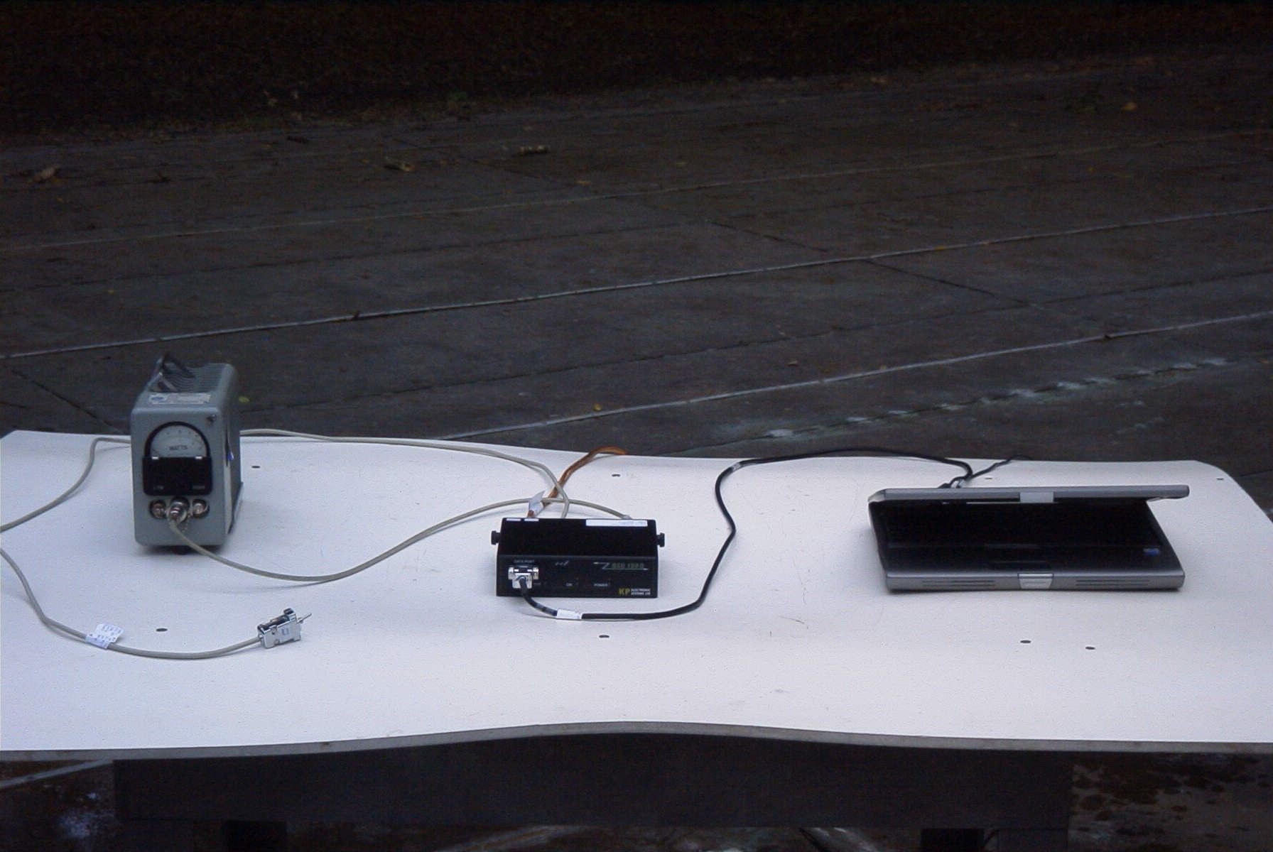
2.1 The basic testing, adjustment and maintenance procedures This document outlines the basic testing, adjustment and maintenance procedures required for initialization BSRU100D wireless radio modemin manufacture condition. 2.2 Equipment Requirement • 12.5VDC (nominal) 5A regulated power supply’s • Radio Service Monitor (IFR COM-120A or equivalent) • Digital oscilloscope • RF Signal generator • Spectrum analyzer • Sinadder • Multimeter • The BSR100D external repair adapter • Assembly cables • RF attenuators kit. • T-96SR digital modemmodule • 486 PC or better (with two RS-232 port COM) • T-96SR Radio Service Software • BSRU100 GUP10 Software • Normal radio shop tools. Create PDF with GO2PDF for free, if you wish to remove this line, click here to buy Virtual PDF Printer 2.3 BSR100D Testing 2.3.1 GENERAL This section of the instruction is intended for testing, adjustment and maintenance BSRU100D modem procedures in manufacture conditions. Only the qualified personnel given examination and past training can be admitted to performance of works specified in this instruction. The deviation from the given instruction can result in damage of the verifying equipment and to infringement of a BSRU100D function. 2.3.2 Basic testing maintenance and adjustments 1.The BSRU100D preparing for the first voltage power feeding. 2.Tx mode transmitter alignment procedure. 3.Rx mode receiver alignment procedure 4.Tx mode modem alignment procedure 5.Rx mode modem alignment procedure 6.Final Tx/Rx BSRU100D modem testing 7.The modem results testing form completion. 2.3.2.1 The BSRU100D preparing for the first voltage power feeding. • Connect the measuring and auxiliary equipment for the Tx mode BSRU100 transceiver alignment procedure in accordance with the manufacture testing setup diagram. • Prepare the BSRU100D transceiver for the first voltage power feeding, as follows: a)Visually inspect the PS and CS sides of the BSRU100D board to eliminate short circuits, breaks, and other defects. • Power ON the 12.95 VDC power supply, as follows: a) Check the current consumption of the BSRU100D transceiver. It must be near 80 mA DC. b) Power OFF the 12.5 VDC power supply. c) Insert the micro-controller chip in its circuit. d) Power ON the 12.95 VDC power supply. e) Check the following: 1. Current consumption of the BSR100D transceiver (it must be 140mA). 2. Self-test LEDs diagnostic. g)Power OFF the 12.95 VDC power supply. 2.3.2.1The Tx mode transmitter alignment procedure: a) Connect the plug of the T96SR module to the BSRU100D on board connector. Create PDF with GO2PDF for free, if you wish to remove this line, click here to buy Virtual PDF Printer b) Power ON the 12.5 VDC power supply. c) Check the following: - Current consumption of the BSRU100D transceiver must be180mA.+/- 10% - Self-test T-96SR module LEDs diagnostic. d) Using the modem setup cable, connect the T-96SR to PC *Do not use this cable to connect a user application The green modem’s LED flashes to indicate the unit in setup mode. e) By PC T96SR Lab Setup Software program to write necessary parameters to T-96SR module. f) Using the radio setup cable, connect the BSR100D to PC and by Use the Gup10 utility programto write the Rx/Tx frequency of the BSR100Dtransceiver to middle frequency band. g) Connect the measuring and auxiliary equipment for the Tx mode BSR100Dtransceiver alignment procedure in accordance with manufacture Tx mode testing setup diagram. h) Screw on cooling radiator to output power transistors l) Power ON the 12.95V DC power supply. i) Short for 10 sec. and release the self-test external PTT button. k) Check DC voltage +2.5V+/- .01V (fulfill a requirement i.) on Tp VC by DVM and adjust it by P3 potentiometer. l) Measure the output power of the BSR100D transceiver. Maximum power reading 10W+15/-10%. *(See m.) m) Adjust trimmer capacitor C168 to receive equal output power on the low and high frequency’s of a working band. Nominal power reading is 10W+15/-10%. n) Check Tx mode current consumption. Current should be 2.6A±5%on the middle frequency of the working band and ±15 %, accordingly on the low and high frequency’s of a working band. o) Using the modem PC DATA cable, connect the BSRU100D Data port to COMPC p) By PCSIMPTERMINALSoftware program(previously having determined all COM ports parameters) send RTS (PTT) command to BSR100D. r) Check DC voltage +2.5V+/- .01Von Tp VC by DVM and adjust it by P3 potentiometer. s) Adjust by P2 for the desired modulation, 2.2 kHz +/-10%carrier deviation Create PDF with GO2PDF for free, if you wish to remove this line, click here to buy Virtual PDF Printer t)Check the synthesizer out put frequency (fulfill a requirement r.). It should be +/- 0.1ppm. Using a trimmer capacitor on the body of the VCTCXO-5DSL, adjust the synthesizer output frequency. u)Check the spurious/harmonics, requirements: Power 50+10log (Pout)or 70 dB, whichever is less. v) Observe by digital oscilloscope the audio signal on “DEMOD OUT” IFRCOM-120ACON. It must be look enough clear and do not have a pattern sensitivity effect, in case of need if ,necessary repeat § r,s and t. w) Power OFF the 12.95 VDC power supply. 1.3.2.2Rx mode receiver alignment procedure a) Power ON the 12.95 VDC power supply. b) Using the radio setup cable, connect the BSRU100D to PC and by Use the Gup10 utility program to write the Rx frequency of the BSRU100D transceiver to the middle frequency band. c) Power OFF the 12.95 VDC power supply. d)ConnectthemeasuringandauxiliaryequipmentfortheRxmodeBSRU100D transceiver alignment procedure in accordance with manufacture Rx mode testing setup diagramand execute (a). e) Set the IFR COM120A RF generator output to frequency that was written in b), to signal level -80 dBm with 2.2 kHz-frequency deviation and internal sine wave modulation 1kHz. f) Observe by digital oscilloscope and sinadder audio signal DATA OUT on he BSRU100D external repair adapter. g) Adjust trimmer capacitors C56, C57 and L41 tunable RF discriminator a…
Text truncated - open the document above for the full version.
RF Exposure Info
FCC RF Exposure Requirements General information: FCCID: H78KPBSRU100D Device category: Mobile per Part 2.1091 Environment: Controlled Exposure Mobile devices that operate under Part 90 of this chapter are subject to routine environmental evaluation for RF exposure prior to equipment authorization or use if they operate at frequencies of 1.5 GHz or below and their effective radiated power (ERP) is 1.5 watts or more. However, compliance with the power density limits of 1.1310 is not required. Antenna: The manufacturer does not specify an antenna. A typical vehicle antenna has a gain of <6 dBi The maximum gain of any antenna used with this transmitter and still meet a 20cm separation distance is 16 dBi. This device has provisions for operation on a vehicle, or from a fixed location. Configuration Antenna p/n Type Max. Gain (dBi) Passenger car Any Any 6 fixed Any Any 16 Operating configuration and exposure conditions: The conducted output power is 10 Watts. Typical use qualifies for a maximum duty cycle factor of 50%. The manufacturer also markets this device only for occupation use. - Part 2.1091 states that devices are excluded from routine evaluation if the EIRP is less than 2.46Watt (or 1.5WERP). - Vehicle Operation: A typical vehicle installation consists of an antenna system with a coaxial cable of the type RG 58 which has a loss of 1dB for a length of 15 feet. 3/12/2007 Page 1 of 3 FCCID: EFOSX450G MPE Calculation: The minimum separation distance is calculated as follows: The limit for occupation/controlled exposure environment above 300 MHz is f/300 mW/cm 2 . 3/12/2007 Page 2 of 3 FCCID: EFOSX450G Channel frequency: 450-470 MHz The conducted power output is 10 watts. The coax loss was taken as 1 dB. Antenna gain was taken as 6 dBi 50% talk time in 6 minutes antenna gain in dBd S f 1500 := power density limit for uncontrolled exposure G1dBd2.15+:= gain in dBi G16=dBi S0.307= CL1:= dB coax loss GG1CL−:= gain numeric Gn10 G 10 := Gn3.162=dB R Po Gn⋅() 4π⋅S⋅ () := inches R 2.54 := R64.054= distance in centimeters required for compliance inches25.218= W10:= power in Watts D1:= Duty Factor in decimal % (1=100%) 1 for FM E15:= exposure time in minutes U30:= (use 6 for controlled and 30 for uncontrolled ) WexpW D⋅ E U ⎛ ⎜ ⎝ ⎞ ⎟ ⎠ ⋅:= PC E U ⎛ ⎜ ⎝ ⎞ ⎟ ⎠ 100⋅:= Wexp5=Watts PC50= % on time PoWexp 1000⋅:= Po510 3 ×=mWatts f460:= Frequency in MHz dBd3.85:= 3/12/2007 Page 3 of 3 FCCID: EFOSX450G
Test Report
FCC PART 90 TEST REPORT APPLICANT KP ELECTRONICS SYSTEMS, LTD. P.O. BOX 42 TEFEN INDUSTRIAL PARK TEFEN, 24959, ISREAL FCC ID H78KPBSRU100D PRODUCT DESCRIPTION UHF RF MODEM DATE SAMPLE RECEIVED 10/30/2006 DATE TESTED 11/1/2006 TESTED BY NAM NGUYEN APPROVED BY MARIO DE ARANZETA TIMCO REPORT NO. 3003UT6TestReport.doc TOTAL PAGES 20 TEST RESULTS PASS FAIL THE ATTACHED REPORT SHALL NOT BE REPRODUCED EXCEPT IN FULL WITHOUT THE WRITTEN APPROVAL OF TIMCO ENGINEERING, INC. 849 NW STATE ROAD 45 NEWBERRY, FL 32669 USA PH: 888.472.2424 OR 352.472.5500 FAX: 352.472.2030 EMAIL: [email protected] HTTP: //WWW.TIMCOENGR.COM Certificate # 0955-01 Applicant: KP ELECTRONIC SYSTEMS, LTD. FCC ID: H78KPBSRU100D Report: V:\K\KP\3003UT6\Extra3003UT6\3003UT6TestReport.doc Page 2 of 20 STATEMENT OF COMPLIANCE.................................................................................. 3 GENERAL INFORMATION .......................................................................................... 4 TEST EQUIPMENT LIST............................................................................................. 5 TEST PROCEDURE ................................................................................................... 6 RF POWER OUTPUT .................................................................................................. 7 MODULATION CHARACTERISTICS............................................................................ 8 VOICE MODULATED COMMUNICATION EQUIPMENT ............................................... 8 AUDIO INPUT VERSUS MODULATION ....................................................................... 8 OTHER MODULATION CHARACTERISTICS ............................................................... 8 OCCUPIED BANDWIDTH (PART 2.1049) .................................................................... 9 SPURIOUS EMISSIONS AT ANTENNA TERMINALS (CONDUCTED)........................... 13 Method of Measuring Conducted Spurious Emissions .............................................. 14 FIELD STRENGTH OF SPURIOUS EMISSIONS......................................................... 15 FREQUENCY STABILITY.......................................................................................... 17 TRANSIENT FREQUENCY RESPONSE ..................................................................... 18 Applicant: KP ELECTRONIC SYSTEMS, LTD. FCC ID: H78KPBSRU100D Report: V:\K\KP\3003UT6\Extra3003UT6\3003UT6TestReport.doc Page 3 of 20 STATEMENT OF COMPLIANCE This equipment has been tested in accordance with the standards identified in the referenced test report. To the best of my knowledge and belief, these tests were performed using the measurement procedures described in this report and demonstrate that the equipment complies with the appropriate standards. No modifications were made to the equipment during testing in order to demonstrate compliance with these standards. I attest that the necessary measurements were made by me or under my supervision, at Timco Engineering, Inc. located at 849 N.W. State Road 45, Newberry, Florida 32669 USA. Certificate # 0955-01 Authorized by: Mario de Aranzeta Signature: <Mario de Aranzeta> Function: Engineer Date: 10/30/2006 Applicant: KP ELECTRONIC SYSTEMS, LTD. FCC ID: H78KPBSRU100D Report: V:\K\KP\3003UT6\Extra3003UT6\3003UT6TestReport.doc Page 4 of 20 GENERAL INFORMATION DUT SPECIFICATIONS The test results relate only to the items tested. DUT Description UHF RF MODEM FCC ID H78KPBSRU100D Operating Frequency 450-470 MHz No. of Channels Single Type of Emission F1D Modulation DRCMSK 110–120Vac/50– 60Hz DC Power DUT Power Source Battery Operated Exclusively Prototype Pre-Production Test Item Production Fixed Mobile Type of Equipment Portable Test Condition Lab Temperature - 26°C Humidity – 50% Modifications to DUT None Test Description DUT was placed in continuous transmit mode of operation. Test Standards ANSI/TIA 603-C:2004, FCC CFR 47 Part 90 Applicant: KP ELECTRONIC SYSTEMS, LTD. FCC ID: H78KPBSRU100D Report: V:\K\KP\3003UT6\Extra3003UT6\3003UT6TestReport.doc Page 5 of 20 TEST EQUIPMENT LIST Device Manufacturer Model Serial Number Cal/Char Date Due Date Analyzer Tan Tower Spectrum Analyzer HP 8566B Opt 462 3138A07786 3144A20661 CAL 12/7/05 12/7/07 Analyzer Tan Tower RF Preselector HP 85685A 3221A01400 CAL 12/7/05 12/7/07 Analyzer Tan Tower Quasi-Peak Adapter HP 85650A 3303A01690 CAL 12/8/05 12/8/07 Analyzer Tan Tower Preamplifier HP 8449B- H02 3008A00372 CAL 12/8/05 12/8/07 Antenna: Biconnical Electro- Metrics BIA-25 1171 CAL 4/29/05 4/29/07 Antenna: Double- Ridged Horn Electro- Metrics RGA-180 2319 CAL 12/29/04 12/29/06 LISN Electro- Metrics ANS-25/2 2604 CAL 10/5/06 10/5/08 Applicant: KP ELECTRONIC SYSTEMS, LTD. FCC ID: H78KPBSRU100D Report: V:\K\KP\3003UT6\Extra3003UT6\3003UT6TestReport.doc Page 6 of 20 TEST PROCEDURE Power Line Conducted Interference: The procedure used was ANSI/TIA 603-C:2004 using a 50uH LISN. Both lines were observed with the DUT transmitting. The bandwidth of the spectrum analyzer was 10 kHz with an appropriate sweep speed. Bandwidth 20 dB: The measurements were made with the spectrum analyzer's resolution bandwidth (RBW) = 1 MHz and the video bandwidth (VBW) = 3 MHz and the span set as shown on plot. Power Output: The RF power output was measured at the antenna feed point using a peak power meter. Antenna Conducted Emissions: The RBW = 100 kHz, VBW = 300 kHz and the span set to 10 MHz and the spectrum was scanned from 30 MHz to the 10 th Harmonic of the fundamental. Above 1 GHz the resolution bandwidth was 1 MHz and the VBW = 3 MHz and the span to 50 MHz. Radiation Interference: The test procedure used was ANSI C63.4-2003 using an Agilent spectrum receiver with preselector. The bandwidth (RBW) of the spectrum receiver was 100 kHz up to 1 GHz and 1 MHz above 1 GHz with an appropriate sweep speed. The VBW above 1 GHz was 3 MHz. The analyzer was calibrated in dB above a microvolt at the output of the antenna. Applicant: KP ELECTRONIC…
Text truncated - open the document above for the full version.
Contact Information
Applicant
Yoram Kenig
Test Firm
Timco Engineering, Inc.Sid Sanders
Technical Specifications
| # | Rule Parts | Frequency Range | Power Output | Emission | Tolerance |
|---|---|---|---|---|---|
| 1 | 90 | 450 MHz - 470 MHz | 10 W | 11K2F1D | 1.5000000000 ppm |
Other Applications from KP Electronic Systems Ltd

H78KPMT2W-MK
Sep 21, 2020UHF Automatic Meter Reading transceiver
Equipment Class
TNB - Licensed Non-Broadcast Station Transmitter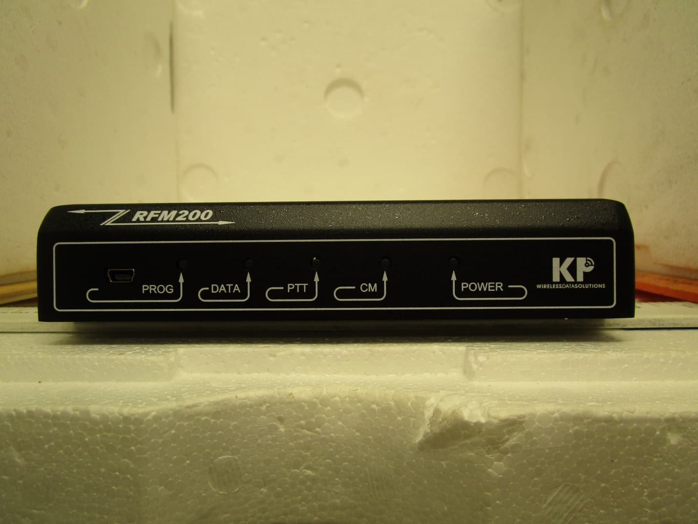
H78KPRFM200U
Apr 15, 2020BASE STATION TRANSCEIVER
Equipment Class
TNB - Licensed Non-Broadcast Station Transmitter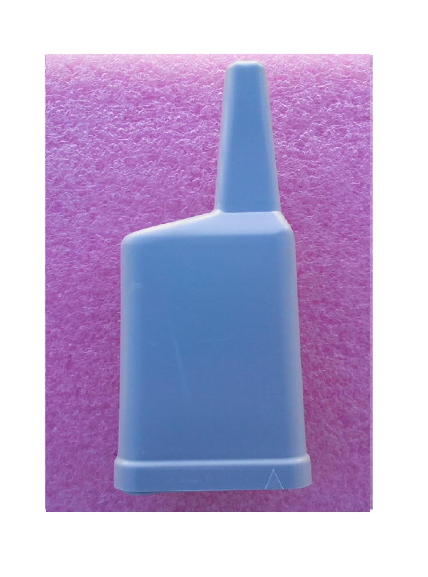
H78KPMT2W
Oct 25, 2015VHF Automatic Meter Reading Transceiver with 2.4 GHz TX
Equipment Class
TNB - Licensed Non-Broadcast Station Transmitter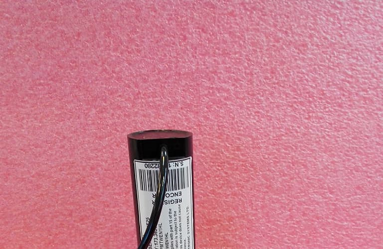
H78KPMTPIT
Apr 01, 2015TRANSMITTER FOR WATER METER
Equipment Class
TNB - Licensed Non-Broadcast Station Transmitter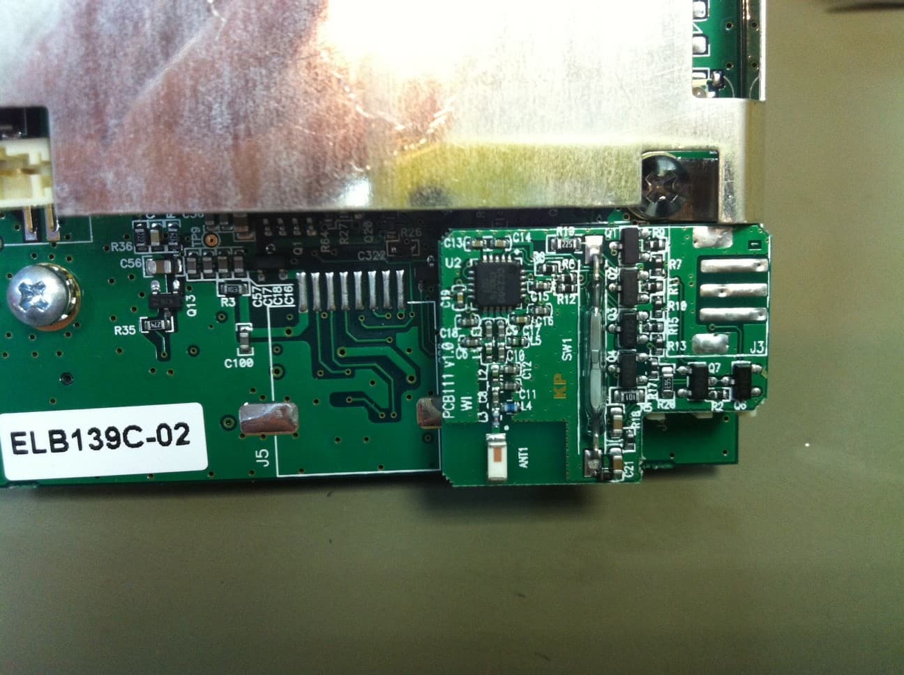
H78KPELB160PIT
Jan 29, 20132.4GHz MODULE
Equipment Class
DXX - Part 15 Low Power Communication Device Transmitter