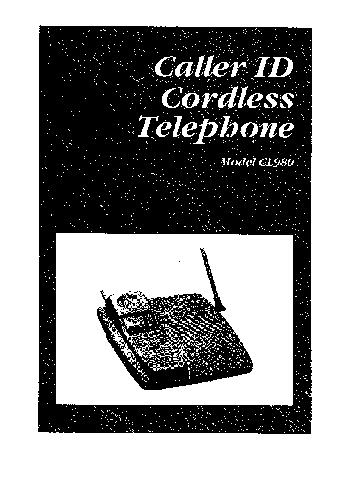
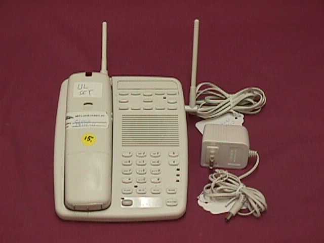
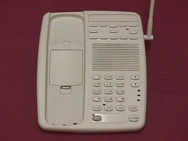
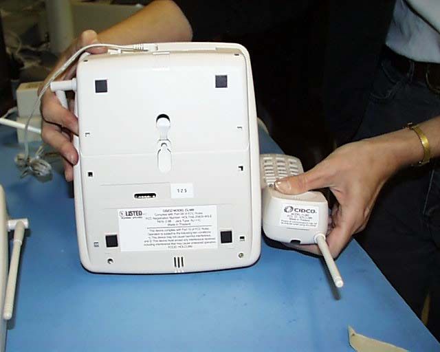
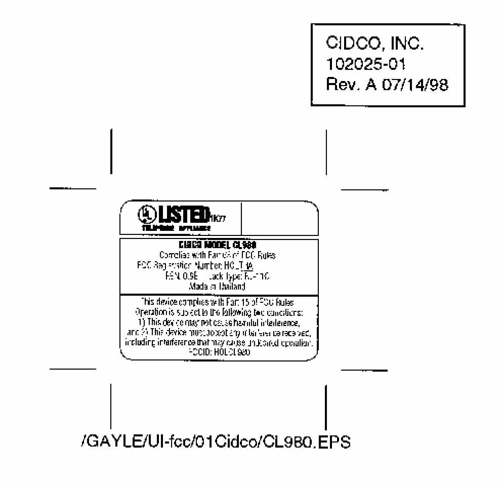
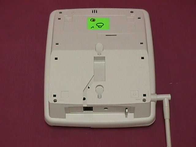
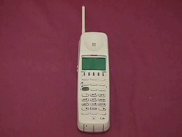
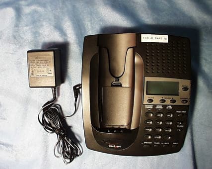
HOLCL980900 MHz Cordless Phone
Cidco Communications Corporation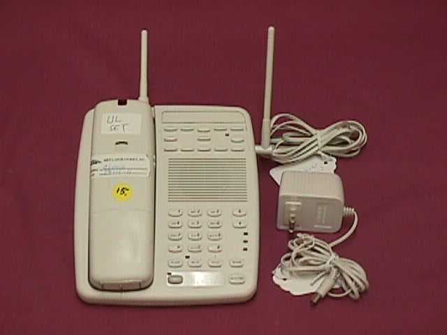
Click to zoom
Application Details
- Equipment Class
- DSS - Part 15 Spread Spectrum Transmitter
- Date of Grant
- Nov 19, 1998
- Application Purpose
- Original Equipment
- Date of Application
- Sep 28, 1998
- Equipment Note
- 900 MHz Cordless Phone
- Frequency Range
- 903.60000000 - 926.40000000
- Country
- United States
Documents & Files
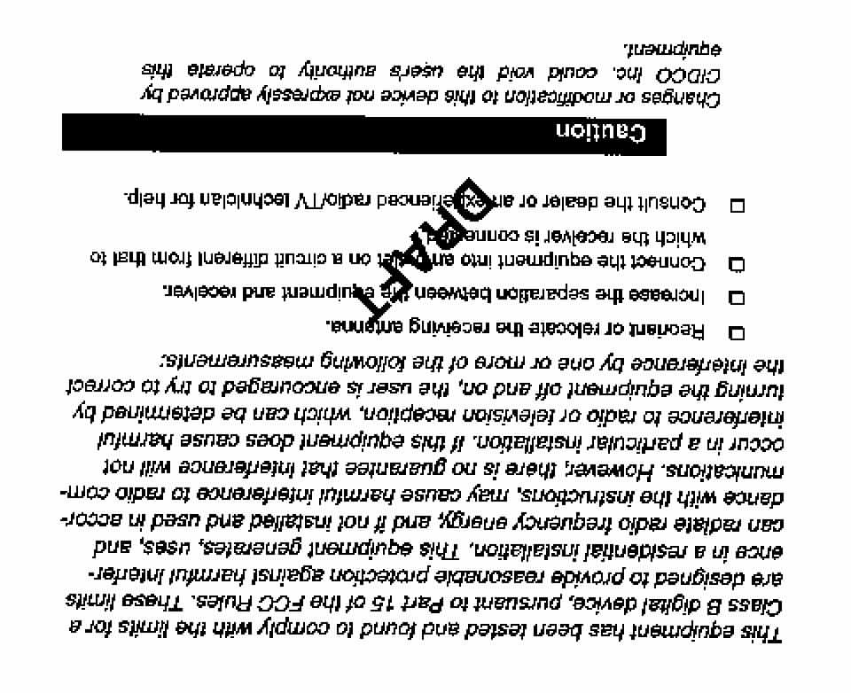
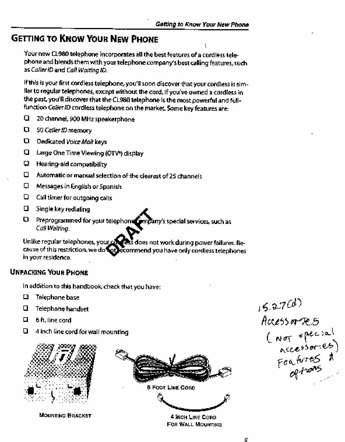
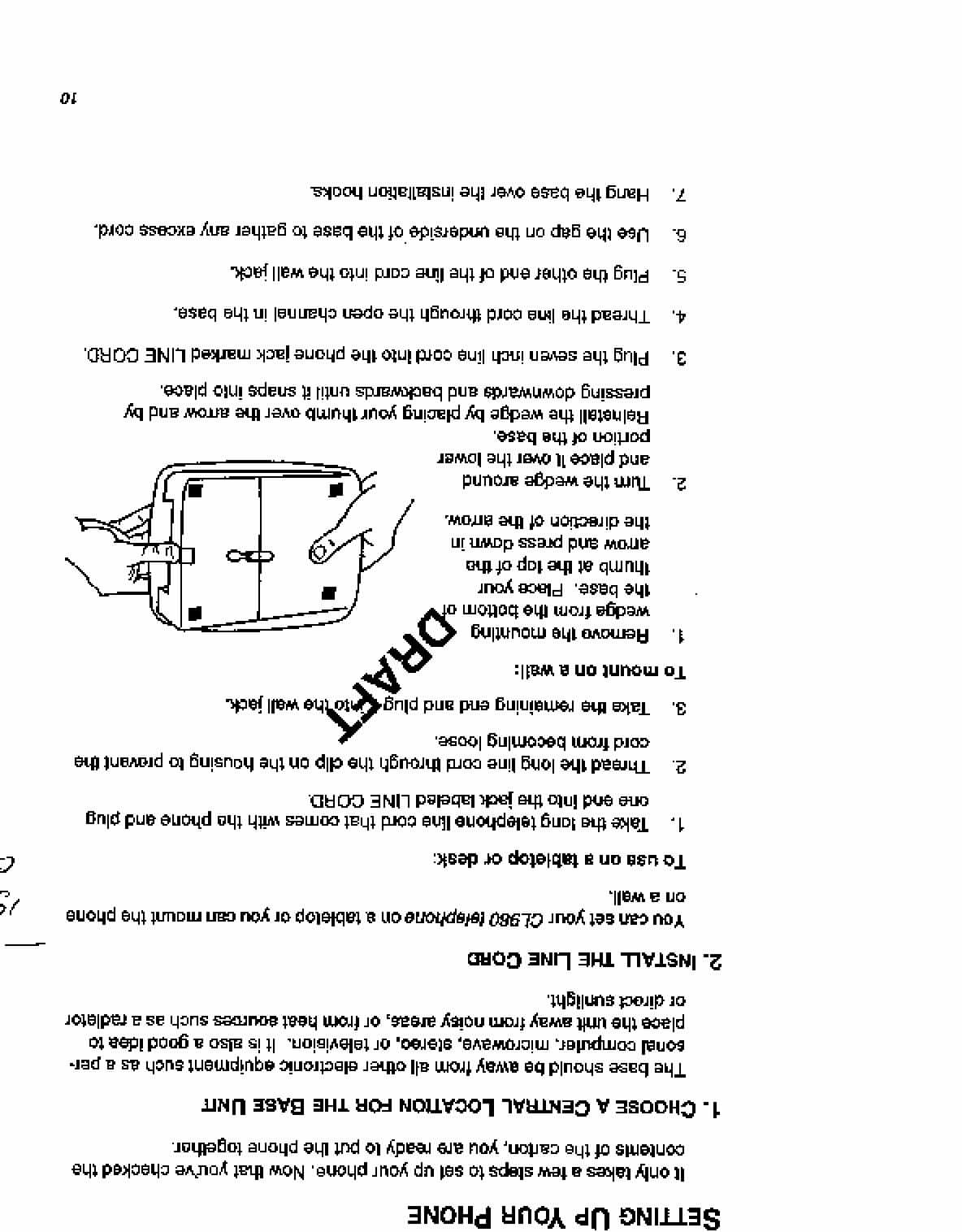
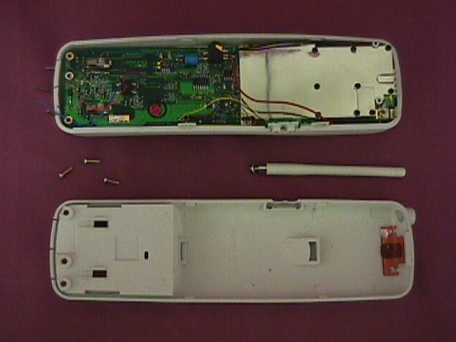
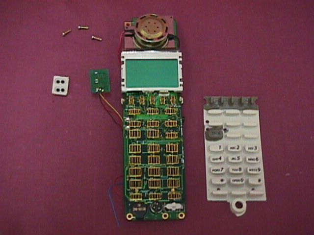
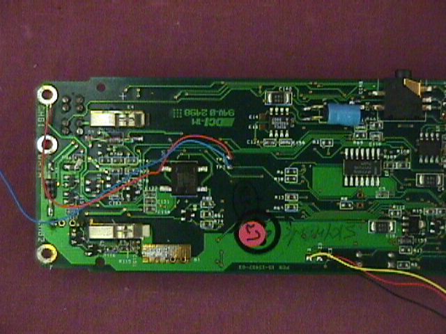
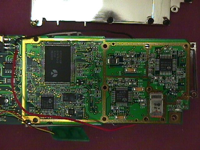
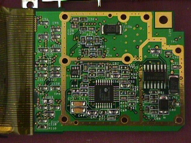
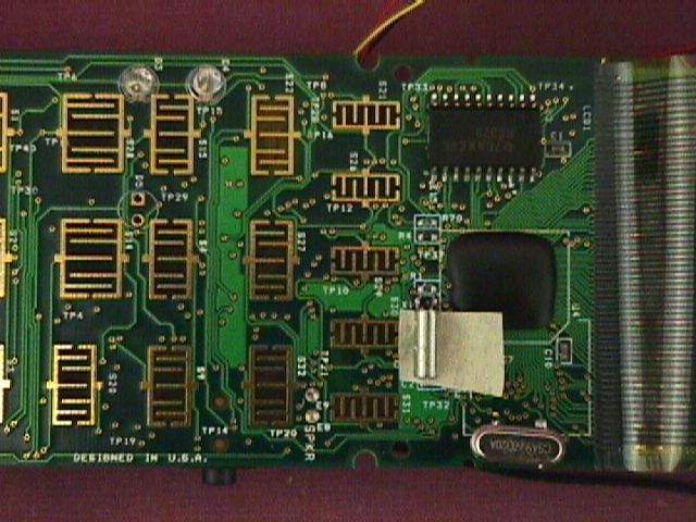
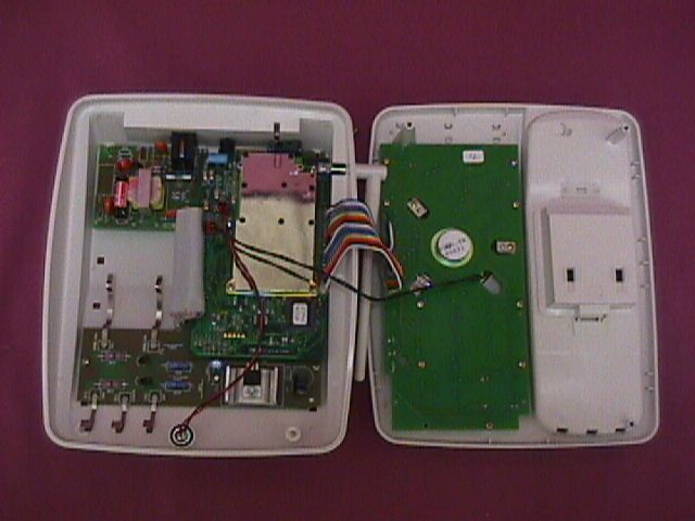
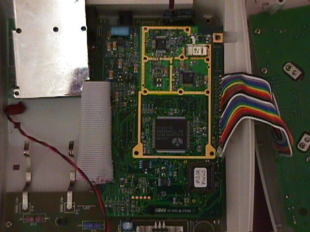
Document Text
Text extracted from the exhibit documents filed with the FCC. Open a document above to read the original.
RF Exposure Info
Cidco FCC ID: HOLCL980 Duty Cycle corrections can be determined\ by T1 and T2 from table 3 of the following page. Given by: Ton = 1.975msec Toff = 2.025msec Duty Cycle calculation: Correction Factor (dB) = 10 log(Ton / (Toff + Ton)) dB = 10 log (1.975/ 2.025 + 1.975)) dB = 10 log (0.494) dB = 3.06 dB Applying the Duty Cycle: E (field strength) = 122 dBuV/m @ 3 meters 122dBuV/m - 3.06 dB = 119 dBuV/m @3 meters P (Power) = (Ed)/30 Watts 2 Corresponds to 238mWatts The Power is less than 300mWatts (corrected) and thus SAR testing is not necessary for this device. Chips per Bit The Chips per bit is determined by T7 and T13 of table 3 on the following page. T7 Data frame time = 133 bits wide x 12.5 usec per bit T13 Chip time = 1.041usec chips per bit = 12.5 usec per bit / 1.041 usec per chip = 12.01 chips/bit This illustrates a rate of 12.01 Chips Per Bit. This rate is greater than the minimum required rate of 11 Chips Per Bit. Timing diagrams are also provided on the following page.
Test Report
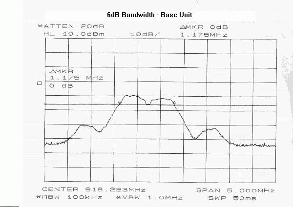
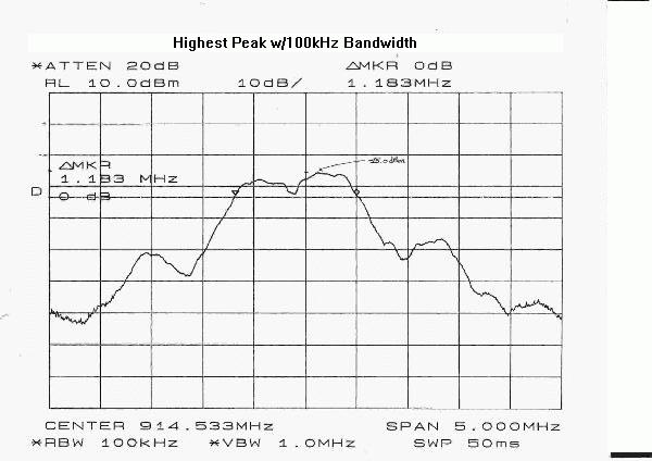
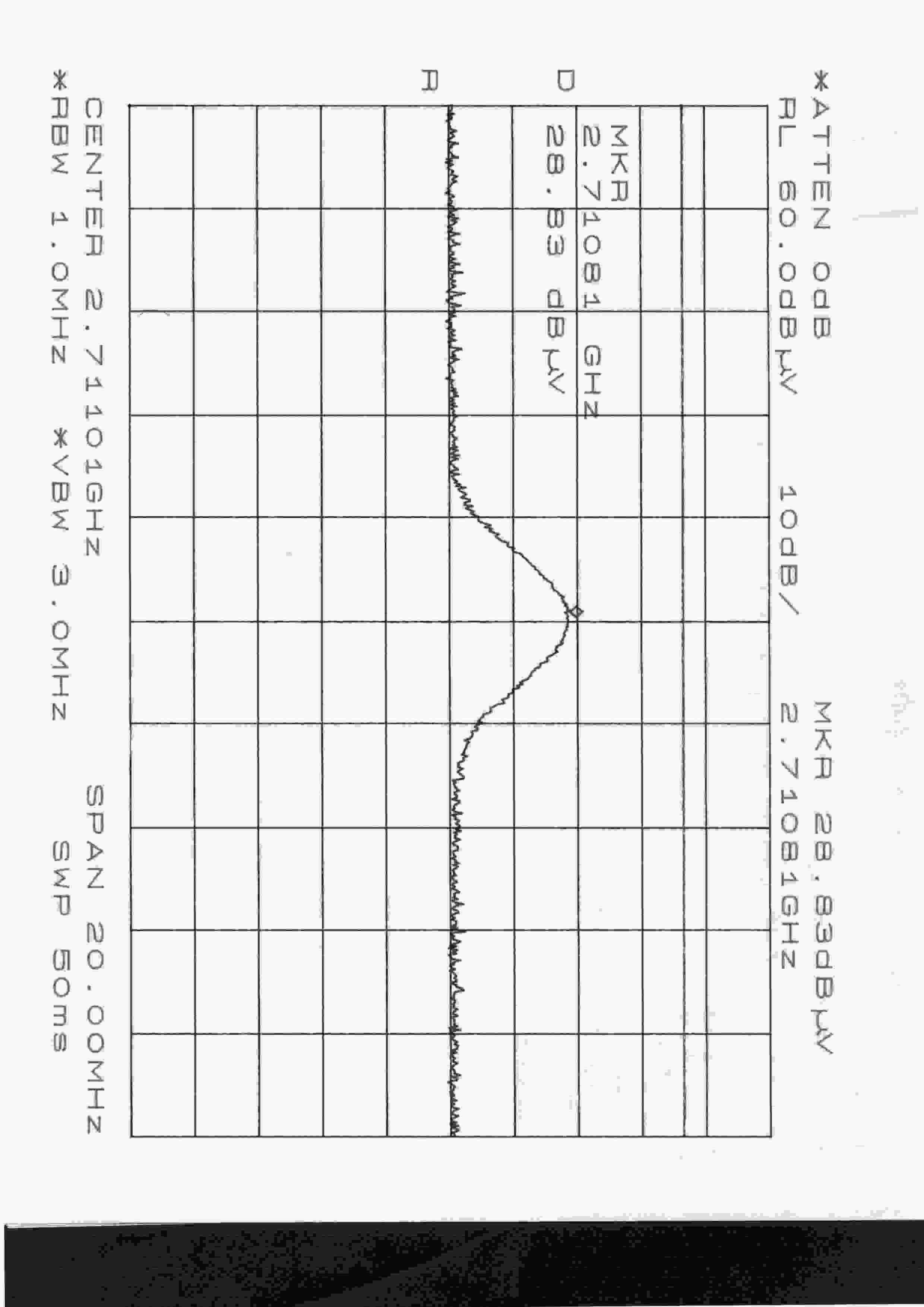
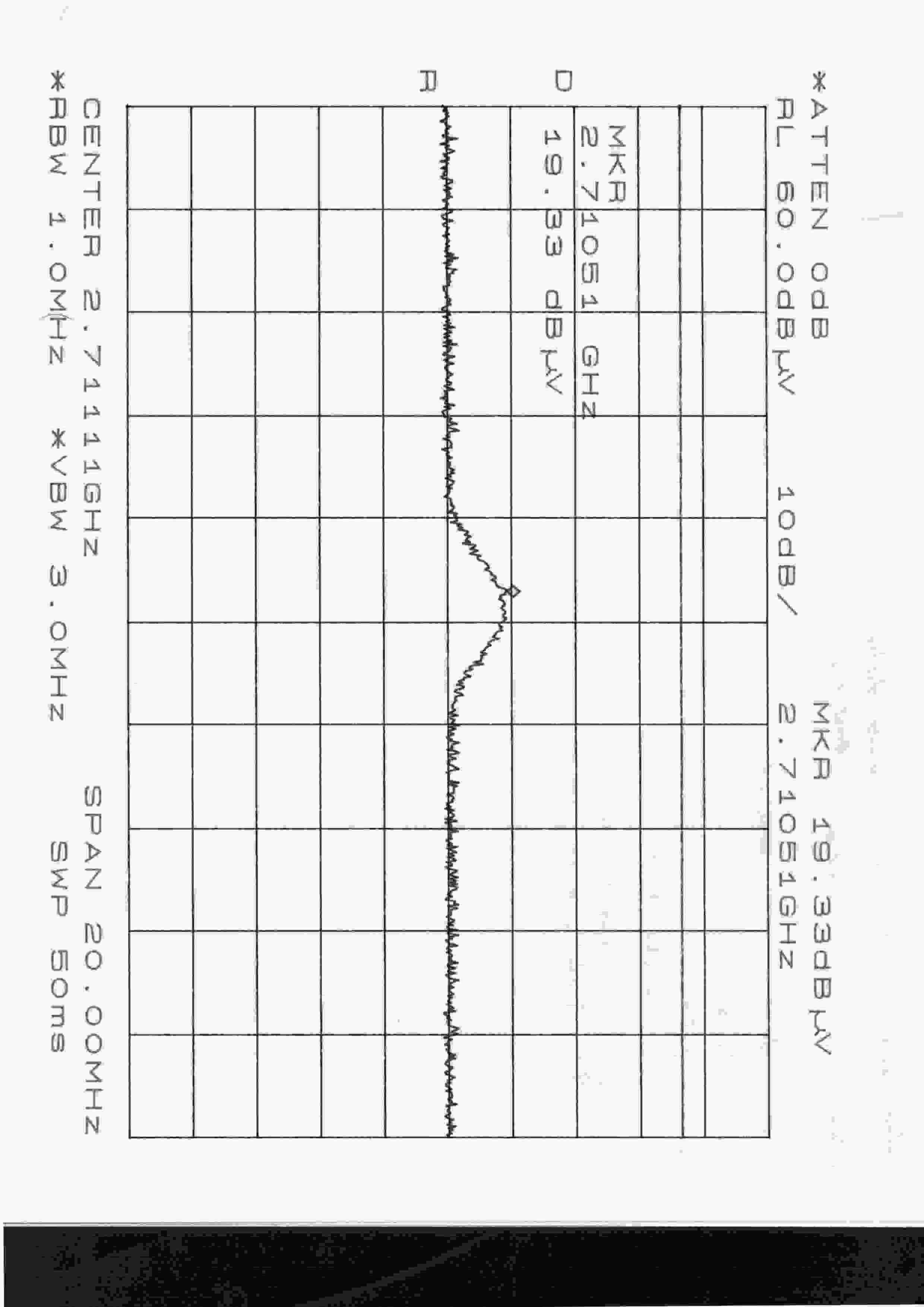
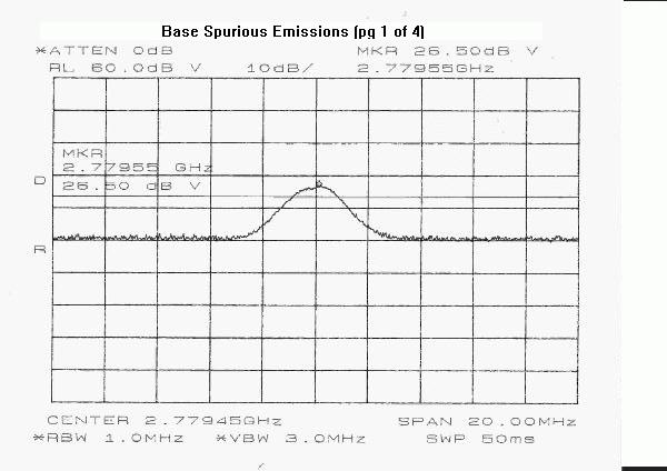
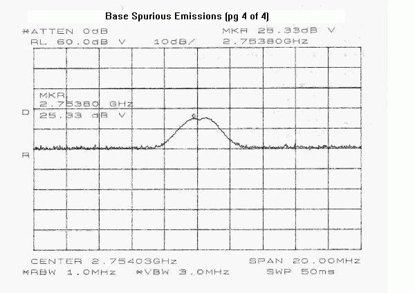
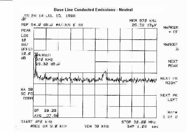
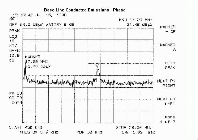
Certification of the CIDCO Model CL980 Cordless Telephone under FCC ID: HOLCL980 as an Intentional Radiator under Title 47 of the CFR, Part 15, Subpart C MET REPORT EMI9386 October 5, 1998 PREPARED FOR: CIDCO, Inc. 220 Cochrane Circle Morgan Hill, CA 95037 PREPARED BY: MET Laboratories, Inc. 914 West Patapsco Avenue Baltimore, Maryland 21230-3432 October 5, 1998 Federal Communications Commission Authorization and Evaluation Division 7435 Oakland Mills Road Columbia, MD 21046 Attention:Applications Examiner Reference:FCC ID: HOLCL980 CIDCO Model CL980 Cordless Telephone Dear Examiner: The following equipment authorization application is presented on behalf of CIDCO , Inc. for the certification of their Model Model CL980 Cordless Telephone. Enclosed, please find a complete data and documentation package demonstrating that this device complies with the technical requirements of 47 CFR, Part 15, Subpart C for an Intentional Radiator. The manufacturer seeks authorization under the FCC ID: HOLCL980. We look forward to an expeditious review of the report presented and a granting of the certification for CIDCO , Inc. If you have any questions or we can be of assistance, in this matter, please call us at (410) 354-3300. Best regards, Kenneth Bass Project Engineer Enclosures APPLICATION FOR EQUIPMENT AUTHORIZATION Certification of the CIDCO Model CL980 Cordless Telephone under FCC ID: HOLCL980 as an Intentional Radiator under Title 47 of the CFR, Part 15, Subpart C MET REPORT EMI9386 October 5, 1998 PREPARED FOR: CIDCO , Inc. 220 Cochrane Circle Morgan Hill, CA 95037 PREPARED BY: MET Laboratories, Inc. 914 West Patapsco Avenue Baltimore, Maryland 21230-3432 Test Engineer:________________________________ Kenneth Bass Reviewed by:________________________________ Christopher Harvey Project Manager FCC ID: HOLCL980 August 12, 1998- 2 -EMI9386 MANUFACTURER & PRODUCT INFORMATION TYPE OF AUTHORIZATION:Certification of an Intentional Radiator FCC IDENTIFIER:HOLCL980 APPLICABLE FCC RULES:15.247(a) thru (e);15.107(a); 15.209(a). CLIENT:CIDCO , Inc. 220 Cochrane Circle Morgan Hill, CA 95037 EQUIPMENT:Model CL980 Cordless Telephone TESTING DATE(S):12, 15, 16, 17, and 20 July 1998 MANUFACTURER'S REPRESENTATIVE:Mr. Can Nguyen ENGINEERING STATEMENT I ATTEST: the measurements shown in this report were made in accordance with the procedures indicated, and that the emissions from this equipment were found to be within the limits applicable. I assume full responsibility for the accuracy and completeness of these measurements, and for the qualifications of all persons taking them. I FURTHER ATTEST: on the basis of the measurements made, the equipment tested is capable of operation in accordance with the requirements of Part 15 of the FCC Rules under normal use and maintenance. ______________________ Kenneth Bass Project Engineer FCC ID: HOLCL980 August 12, 1998- 3 -EMI9386 MODIFICATIONS STATEMENT I ATTEST: that the product will be manufactured with all modifications for Part 15 compliance as submitted in this report. Modifications made during testing appear below: 1. Screws were added to the exterior case, at the transmit antenna end, to enhance contact between the top and bottom chassis plates. 2. A metal can was added to enclose the output amplifier circuitry. 3. A filter circuit was added to the output amplifier and at the output of the PLL. INTRODUCTION An EMI evaluation to determine compliance of the CIDCO Model CL980 Cordless Telephone with the requirements of Part 15, Subpart C for Intentional Radiators was conducted. (All references are to the most current version of Title 47 of the Code of Federal Regulations in effect.) In accordance with §2.1033(b), the following test report is presented in support of the application for grant of certification of the CIDCO Model CL980 Cordless Telephone. CIDCO, Inc. should retain a copy of this document for at least one year after the manufacturing of the CIDCO Model CL980 Cordless Telephone has been permanently discontinued, as per §2.938(c). TEST SITE All testing was conducted at MET Laboratories, Inc., 914 West Patapsco Avenue, Baltimore, Maryland 21230-3432. Radiated emissions measurements were performed on a three-meter open air test site (OATS). In accordance with §2.948, a complete site description is on file with the FCC Laboratory Division as 31040/SIT/MET. TEST SUMMARY The EUT is a direct sequence spread spectrum telephone consisting of a base and a hanset. The phone has 20 channel capability. The worst case channel was used for making measurements for comparison to the FCC rules under 15.247. MEASUREMENT PROCEDURES As required by §15.207(a) of CFR 47, conducted emissions measurements were made in accordance with FCC ID: HOLCL980 August 12, 1998- 4 -EMI9386 ANSI C63.4-1992 "Methods of Measurement of Radio-Noise Emissions from Low-Voltage Electrical and Electronic Equipment in the Range of 9kHz to 40 GHz". The measurements were performed over the frequency range of 0.45 MHZ to 30 MHZ using a 50 S/50 μH LISN as the input transducer to an EMI/Field Intensity Meter. The measurements were made with the detector set for "peak" amplitude within an IF bandwidth of 10 kHz or for "quasi-peak" within a bandwidth of 9 kHz. The tests were conducted in a RF-shielded enclosure. As required by §15.209(a) of CFR 47, radiated emissions measurements were made in accordance with the general procedures of ANSI C63.4-1992 "Methods of Measurement of Radio-Noise Emissions from Low- Voltage Electrical and Electronic Equipment in the Range of 9kHz to 40 GHz". The measurements were performed over the frequency range of 9 kHz to the tenth harmonic of the carrier using the following equipment: Frequency RangeInput TransducerMeasurement Instrumentation 9 kHz to 30 MHZPassive Rod AntennaSpectrum Analyzer 30 MHZ to 1 GHzDipole Antenna SetSpectrum Analyzer above 1 GHzDouble Ridged Guide HornSpectrum Analyzer The measurements were made with the detector set for "quasi-peak" within a bandwidth of …
Text truncated - open the document above for the full version.
Test Report
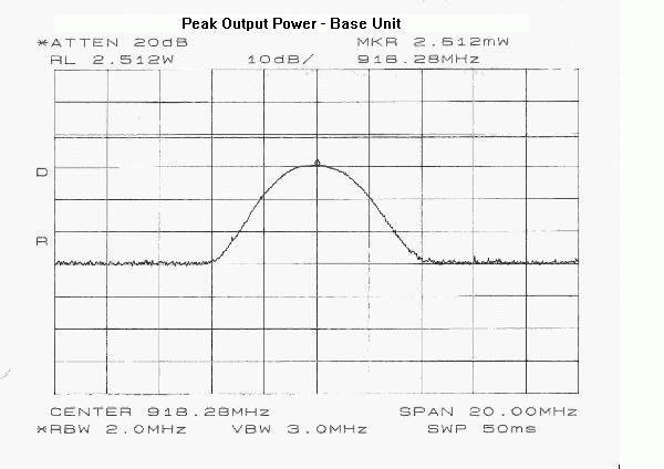
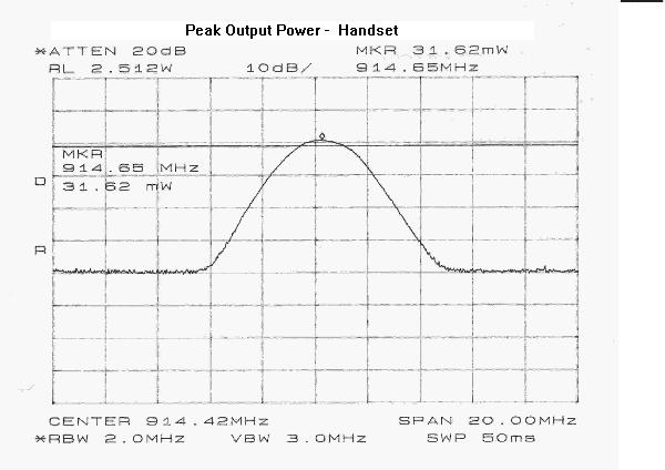
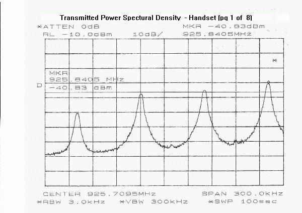
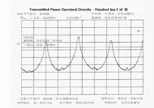
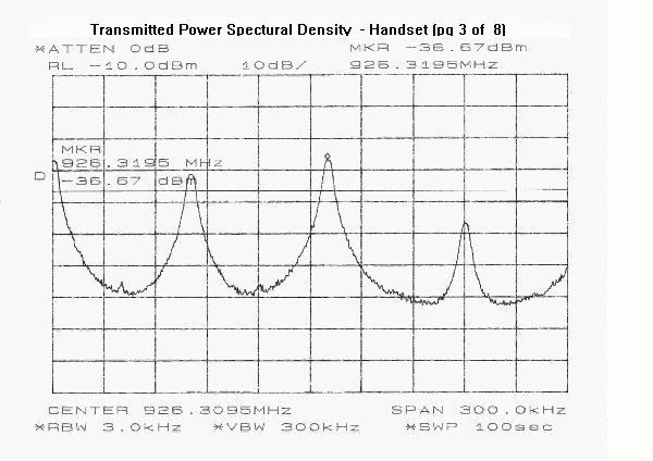
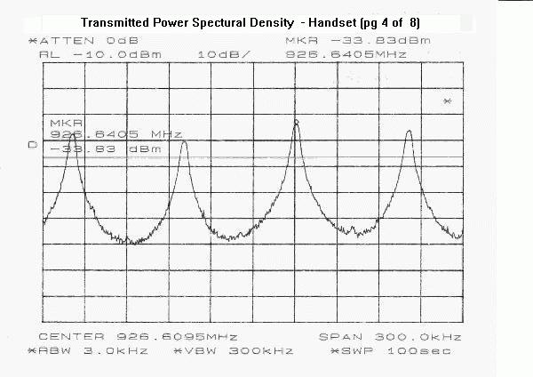
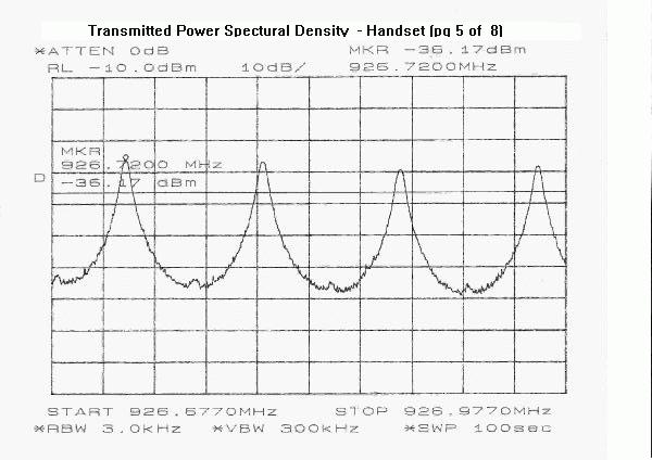
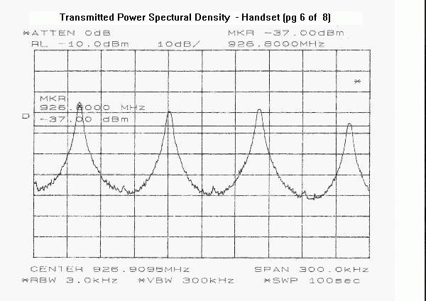
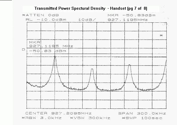
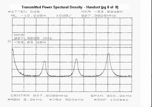
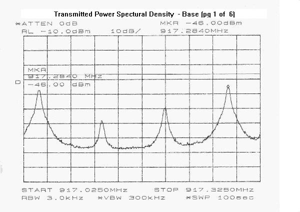
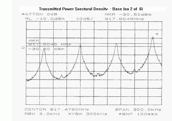
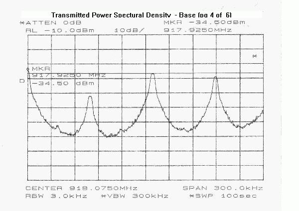
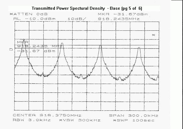
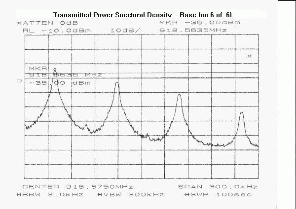
03 Nov 1998 To: Joe Dichoso ([email protected]) From: Ken Bass ([email protected]) Re:FCC ID: HOLCL980 (correspondence ID: 4310) Dear Joe: The following items are in response to your inquires as provided in your e-mail (correspondence ID: 4310) in reference to the above listed application: 1) The frequency range of the base unit and handset unit from the center frequency of the lowest channel to the center frequency of the highest channel A1) The frequency range for both the handset and the base unit are from 903.6 to 926.4 MHz. The handset and base operate on any of 20 channels in this frequency band. The Tx and Rx channels for the handset and base are the same across the frequency band. 4) Verification of compliance with 15.203 ( antenna requirements) 4A) The EUT ( both Handset and Base inclusive) have non-detachable antenna elements. Disassembly of the units would be necessary, for antenna replacement. Therefore, by virtue of the design, the EUT complies with the requirements of 15.203. 6) Calculation of the power output for the base unit and the handset using the worst case field strength using Po= (E*d)squared/30. 6A) from page 9 of the submitted test report, the Power output levels when covered to a field strength as recommended above gives: Handset Po = ((1.26V/m * 3m)) squared/30 = 476 mW Base = (0.35 V/m * 3m)) squared/30 = 37.8 mW 7) Indicate compliance with the RF safety requirements. 7A) Compliance with the RF safety requirements is based on CFR47, 2.1093 paragraph (c), which states: “All other portable transmitting devices are categorically excluded from routine environmental evaluation for RF exposure except as specified in 1.1307© and (d)” . Since the EUT does not fall into any described categories of these Rule parts, it is considered “other”, and thus is found to be exempt from the requirements. Page 2 Re: FCC ID: HOLCL980 (correspondence ID: 4310) Responses Cont’d - 8) At what distance were the radiated power density measurements made? From the worst case field strength calculate the power density using Po=(E*d) 2 / 30. 8A) The Power Spectral Density measurements were made at 1m. Similarly, the Po calculation at the worst case field strength for the handset and base (from pg 23 of the report) are given by: Handset Po = ((0.072)(1)) 2 / 30 = 174 uW = -8.5dBm Base Po = ((0.106)(1)) 2 / 30 = 375 uW = -4.0dBm 10) What is the theoretical processing gain? Whats the spread rate? What is the data rate? 10A) The theoretical Processing gain is given by: G p = (S/N) o + M j + L sys = 8dB BPSK + J/S + 2dB max G p > 10 dB From DS SS chip manufacturer Jamming Test description file: “Procga1.jpg” Spreading rate = 960 kbps and Data rate = 1000 bps
Contact Information
Applicant
Ron Anglikowski(Engineering Director)
Technical Contact
MET Laboratories, Inc.Ken H Bass
[email protected](410)354-3300
914 West Patapsco Ave. · Baltimore, Maryland · United States
Non-Technical Contact
MET Laboratories, Inc.Terri Wolf
[email protected](410)354-3300
Test Firm
MET Laboratories, Inc.John Mason
Technical Specifications
| # | Rule Parts | Frequency Range | Power Output |
|---|---|---|---|
| 1 | 15C | 903.6 MHz - 926.4 MHz | 476.00 mW |
Other Applications from Cidco Communications Corporation
HOLE272
Jun 25, 20032.4GHz DSS Cordless Telephone
Equipment Class
DTS - Digital Transmission System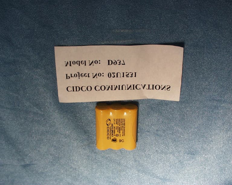
HOLD93X
Oct 06, 2002900MHz Digital Spread Spectrum Cordless Phone
Equipment Class
DTS - Digital Transmission System
HOLCL906
Jun 27, 2002900MHz Cordless Telephone System
Equipment Class
DXT - Part 15 Low Power Transceiver, Rx Verified
HOLD933
May 12, 2002900MHz DSS Cordless Telephone System
Equipment Class
DSS - Part 15 Spread Spectrum Transmitter
HOLD271
Mar 07, 20022.4GHZ Spread Spectrum Cordless Telephone
Equipment Class
DSS - Part 15 Spread Spectrum Transmitter