IAJ210NFRS 2-Way Radios (Walkie Talkie)
Kiddesigns Inc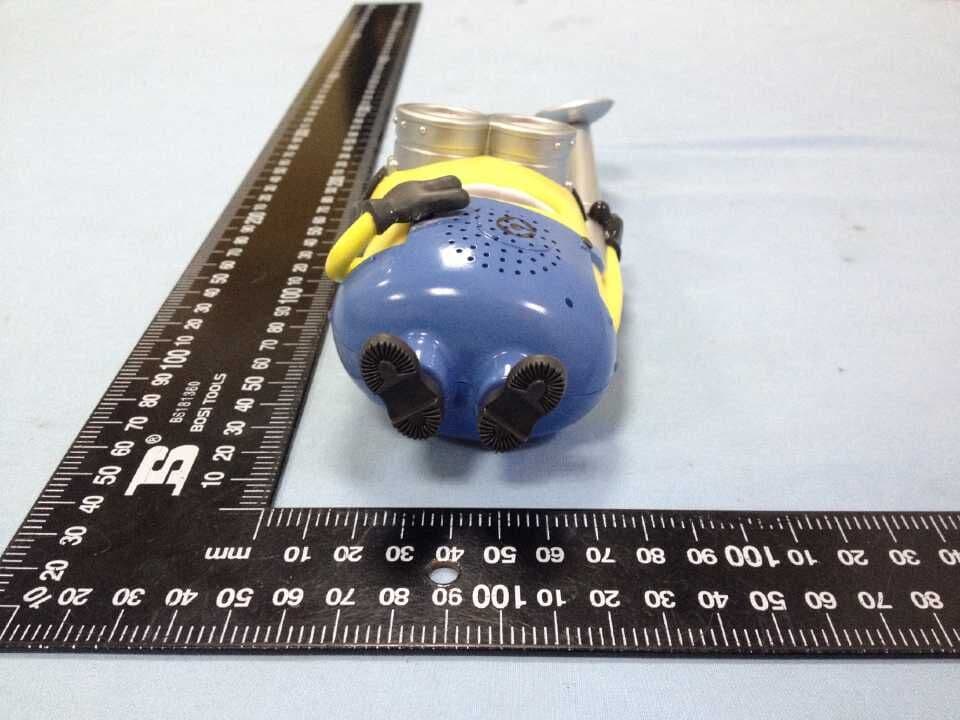
Click to zoom
Application Details
- Equipment Class
- FRF - Part 95 Family Radio Face Held Transmitter
- Date of Grant
- Jun 22, 2015
- Application Purpose
- Original Equipment
- Date of Application
- Jun 22, 2015
- Equipment Note
- FRS 2-Way Radios (Walkie Talkie)
- Frequency Range
- 462.56250000 - 462.71250000
- Company
- Kiddesigns Inc
- Country
- United States
Documents & Files
Document Text
Text extracted from the exhibit documents filed with the FCC. Open a document above to read the original.
Users Manual
FRS FREQUENCY CHART (MHz) CH. No. CH. Freq. CH. No. CH. Freq. CH. No. CH. Freq. 1 462.5625 4 462.6375 7 462.7125 2 462.5875 5 462.6625 --- --- 3 462.6125 6 462.6875 --- --- FCC Warning To ensure that your expose to RF electromagnetic energy is Within the FCC allowable limits for occupational use, alwaysAdhere to the following guidelines: z DO NOT operate the radio without a proper antenna attached, as this may damaged the radio And may also cause you to exceed FCC RF exposure limits, A proper antenna is the antenna Supplied with this radio by the manufacturer or antenna specifically authorized by the manufacturer for use with this radio. z DO NOT transmits for more than 50% of total radio use time (“50% duty cycle). Transmitting more than 50% of the time can cause FCC RF exposure compliance requirements to be exceeded. The radio is transmitting when the “TX indicator” lights red. You can cause the radio to transmit by pressing the “PTT” switch. z ALWAYS kepp the antenna at least 2.5cm (1 inch) away from the body when transmitting and Only use the belt-clip which is listed in instructions when attaching the radio to your belt, etc., to ensure FCC RF exposure compliance requirements are not exceeded. The information listed above provides the user with the information needed to make him or her aware of RF exposure, and what to do to as-sure that this radio operates with the FCC RF exposure limits of this radio. This device complies with Part 15 of the FCC Rules. Operation is subject to the following two conditions: (1) this device may not cause harmful interference, and (2) this device must accept any interference received, including interference that may cause undesired operation NOTE 1: This equipment has been tested and found to comply with the part 95 of the FCC rules. These limits are designed to provide reasonable protection against harmful interference in a residential installation. This equipment generates, uses and can radiate radio frequency energy and, if not installed and used in accordance with the instructions, may cause harmful interference to radio communications. However, there is no guarantee that interference will not occur in a particular installation. If this equipment does cause harmful interference to radio or television reception, which can be determined by turning the equipment off and on, the user is encouraged to try to correct the interference by one or more of the following measures: - Reorient or relocate the receiving antenna. - Increase the separation between the equipment and receiver. -Connect the equipment into an outlet on a circuit different from that to which the receiver is connected. -Consult the dealer or an experienced radio/TV technician for help. Any changes or modifications not expressly approved by the manufacturer could void the user’s authority to operate the equipment.
External Photos
KIDDESIGNS INC. Model: MS-210 REPORT NO.: STR15058272I FCC PART 95 EXHIBIT 2 - EUT EXTERNAL PHOTOGRAPHS EUT View 1 EUT View 2 KIDDESIGNS INC. Model: MS-210 REPORT NO.: STR15058272I FCC PART 95 EUT View 3 EUT View 4 KIDDESIGNS INC. Model: MS-210 REPORT NO.: STR15058272I FCC PART 95 EUT View 5 EUT View 6 KIDDESIGNS INC. Model: MS-210 REPORT NO.: STR15058272I FCC PART 95 EUT View 7
ID Label/Location Info
KIDDESIGNS INC. Model: MS-210 REPORT NO.: STR15058272I FCC PART 95 EXHIBIT 1- PRODUCT LABELING Proposed FCC ID Label Format FCC ID: IAJ210N Specifications: Text is Black in color and justified. Labels are printed in indelible ink on permanent adhesive silk-screened onto the EUT or shall be affixed at a conspicuous location on the EUT. Proposed Label Location on EUT FCC ID Label Location
ID Label/Location Info
KIDDESIGNS INC. Model: MS-210 REPORT NO.: STR15058272I FCC PART 95 EXHIBIT 1- PRODUCT LABELING Proposed FCC ID Label Format FCC ID: IAJ210N Specifications: Text is Black in color and justified. Labels are printed in indelible ink on permanent adhesive silk-screened onto the EUT or shall be affixed at a conspicuous location on the EUT. Proposed Label Location on EUT FCC ID Label Location
Internal Photos
KIDDESIGNS INC. Model: MS-210 REPORT NO.: STR15058272I FCC PART 95 EXHIBIT 3 - EUT INTERNAL PHOTOGRAPHS EUT Housing and Board View 1 EUT Housing and Board View 2 KIDDESIGNS INC. Model: MS-210 REPORT NO.: STR15058272I FCC PART 95 Solder Board-Component View 1 Solder Board-Component View 2 KIDDESIGNS INC. Model: MS-210 REPORT NO.: STR15058272I FCC PART 95 Solder Board-Component View 3 Solder Board-Component View 4 KIDDESIGNS INC. Model: MS-210 REPORT NO.: STR15058272I FCC PART 95 Solder Board-Component View 5
RF Exposure Info
RF EXPOSURE EXHIBIT Standard Applicable According to FCC KDB 447498 D01 V05r02 clause 6, the power thresholds and operating conditions in Appendix A are used to determine SAR test requirements for PTT radios required to comply with the general population exposure limit. When the occupational exposure limit applies, these power thresholds are increased by a factor of five (5) to determine the test requirements. SAR is required for PTT devices with maximum output power greater than these thresholds. Evaluation: RF Exposure Conditions: The two-way radio device is intended for use in the Held to face exposure condition and the general population RF exposure environment, and always keep the antenna at least 2.5 cm (1 inch) away from the body. Transmission Mode: The two-way radio device utilizes a FM modulation with Push-to talk mode. Duty Cycle: The two-way radio device utilizes a FM modulation with a duty cycle of 50% when actual operating duty factor is ≤ 50 %. RF Output Power Tx frequency range: 462.6625MHz Antenna-to-tissue separation: ≥2.5 cm Maximum Output Power: 17.78dBm (59.9791mW) Maximum Antenna Gain: 0 dBi Maximum Duty Factor: 50% Limit: 112mW x 2 = 224mW Source-based time-averaged conducted output power is 59.9791 mW = < 224 mW
Test Report
KIDDESIGNS INC. Model: MS-210 REPORT NO.: STR150582721I PAGE 1 OF 17 FCC PART 95 FCC Part 95 Measurement and Test Report For KIDDESIGNS INC. 1299 Main Street, Rahway, NJ 07065-0901, United States FCC ID: IAJ210N Test Standards: FCC Part 95 Product Description: FRS 2-way Radios (Walkie Talkie) Tested Model: MS-210 Report No.: STR15058272I Tested Date: 2015-05-27 to 2015-06-06 Issued Date: 2015-06-08 Tested By: Vigoss Liang / Engineer Reviewed By: Lahm Peng / EMC Manager Approved & Authorized By: Jandy so / PSQ Manager Prepared By: Shenzhen SEM.Test Technology Co., Ltd. 1/F, Building A, Hongwei Industrial Park, Liuxian 2nd Road, Bao'an District, Shenzhen, P.R.C (518101) Tel.: +86-755-33663308 Fax.: +86-755-33663309 Website: www.semtest.com.cn Note: This test report is limited to the above client company and the product model only. It may not be duplicated without prior permitted by Shenzhen SEM.Test Technology Co., Ltd. KIDDESIGNS INC. Model: MS-210 REPORT NO.: STR150582721I PAGE 2 OF 17 FCC PART 95 TABLE OF CONTENTS 1. GENERAL INFORMATION ................................................................................................................................... 3 1.1 PRODUCT DESCRIPTION FOR EQUIPMENT UNDER TEST (EUT) ............................................................................... 3 1.2 TEST STANDARDS ................................................................................................................................................... 4 1.3 TEST METHODOLOGY ............................................................................................................................................. 4 1.4 TEST FACILITY ....................................................................................................................................................... 4 1.5 EUT SETUP AND TEST MODE ................................................................................................................................. 5 2. SUMMARY OF TEST RESULTS ........................................................................................................................... 6 3. RADIATED OUTPUT POWER (ERP) ................................................................................................................... 7 3.1 STANDARD APPLICABLE ......................................................................................................................................... 7 3.2 TEST EQUIPMENT LIST AND DETAIL ....................................................................................................................... 7 3.3 TEST PROCEDURE ................................................................................................................................................... 7 3.4 ENVIRONMENTAL CONDITIONS .............................................................................................................................. 7 3.5 TEST RESULT.......................................................................................................................................................... 8 4. OCCUPIED BANDWIDTH OF EMISSION .......................................................................................................... 9 4.1 STANDARD APPLICABLE ......................................................................................................................................... 9 4.2 TEST EQUIPMENT LIST AND DETAILS ..................................................................................................................... 9 4.3 TEST PROCEDURE ................................................................................................................................................... 9 4.4 ENVIRONMENTAL CONDITIONS .............................................................................................................................. 9 4.5 TEST RESULTS/MASKS ......................................................................................................................................... 10 5. UNWANTED RADIATED EMISSION ................................................................................................................ 11 5.1 MEASUREMENT UNCERTAINTY ............................................................................................................................ 11 5.2 STANDARD APPLICABLE ....................................................................................................................................... 11 5.3 TEST EQUIPMENT LIST AND DETAILS ................................................................................................................... 11 5.4 TEST PROCEDURE ................................................................................................................................................. 11 5.5 ENVIRONMENTAL CONDITIONS ............................................................................................................................ 12 5.6 SUMMARY OF TEST RESULTS/PLOTS .................................................................................................................... 12 6. FREQUENCY STABILITY ................................................................................................................................... 13 6.1 STANDARD APPLICABLE ....................................................................................................................................... 13 6.2 TEST EQUIPMENT LIST AND DETAILS ................................................................................................................... 13 6.3 TEST PROCEDURE ................................................................................................................................................. 13 6.4 TEST RESULT........................................................................................................................................................ 14 7. MODULATION CHARA…
Text truncated - open the document above for the full version.
Test Setup Photos
KIDDESIGNS INC. Model: MS-210 REPORT NO.: STR15058272I FCC PART 95 EXHIBIT 4 - TEST SETUP PHOTOGRAPHS Radiation Emission Test Setup (30MHz to 1GHz) Radiation Emission Test Setup (Above 1GHz)
Contact Information
Applicant
David Stetin(Product Safety & Compliance Officer)
Test Firm
Shenzhen SEM.Test Technology Co., Ltd.Jandy So
Technical Specifications
| # | Rule Parts | Frequency Range | Power Output | Emission | Tolerance |
|---|---|---|---|---|---|
| 1 | 95B | 462.5625 MHz - 462.7125 MHz | 59.98 mW | 11K0F3E | 0.6000000000 ppm |
Other Applications from Kiddesigns Inc
IAJ214SC10A
Jul 20, 2026214 Multi-Channel Walkie Talkies
Equipment Class
FRF - Part 95 Family Radio Face Held Transmitter
IAJ210C10A
Apr 20, 2026walkie talkie
Equipment Class
FRF - Part 95 Family Radio Face Held Transmitter
IAJ202C10C
Dec 12, 2025202, 207, 210, 216 Walkie talkies
Equipment Class
FRF - Part 95 Family Radio Face Held Transmitter
IAJ212A
Jun 30, 2020XX-212 WALKIE TALKIES
Equipment Class
FRF - Part 95 Family Radio Face Held Transmitter
IAJ200
May 06, 2015Walkie Talkie
Equipment Class
DXT - Part 15 Low Power Transceiver, Rx Verified