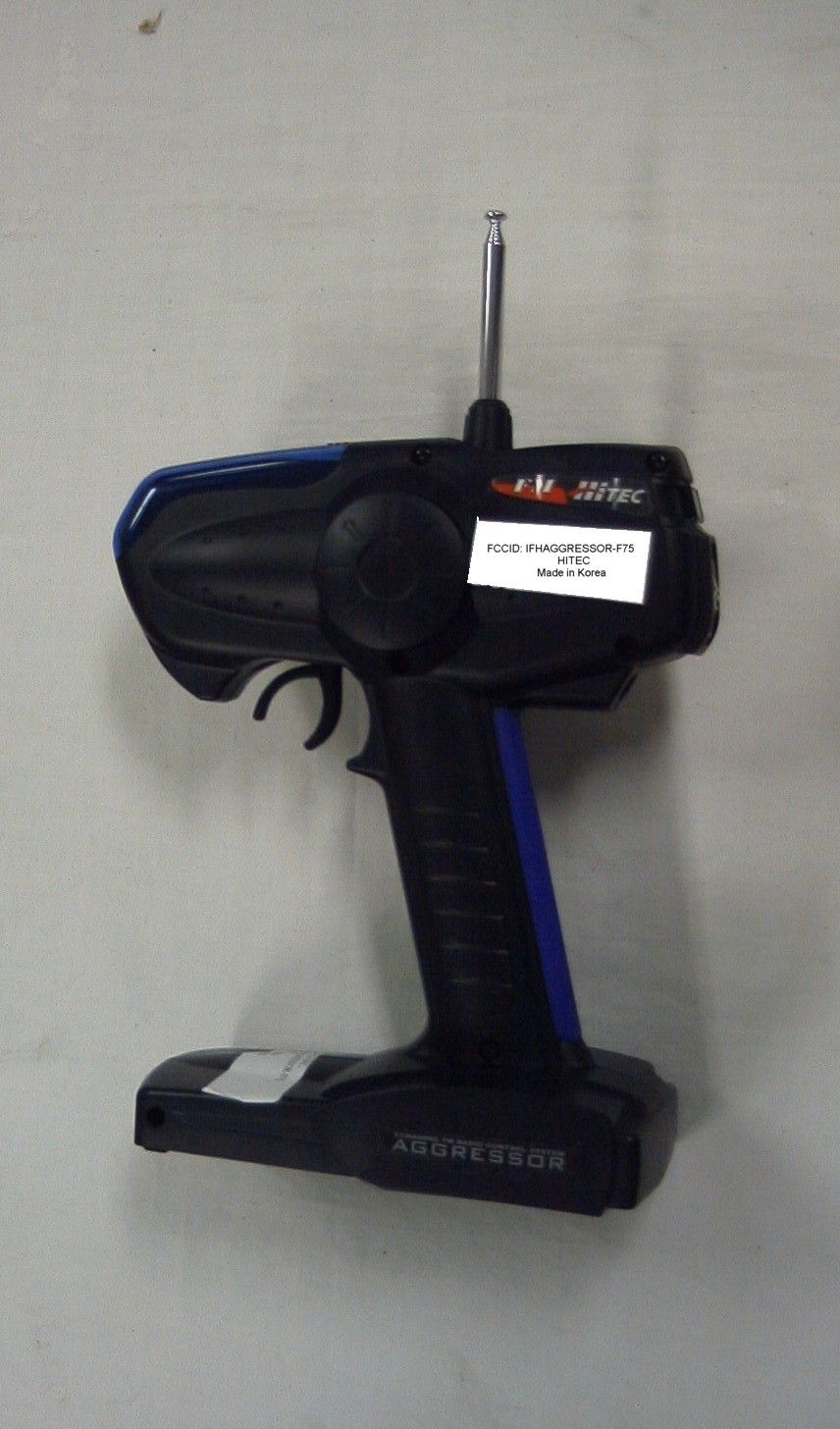
IFHAGGRESSOR-F75REMOTE CONTROL TRANSMITTER
Hitec RCD Inc.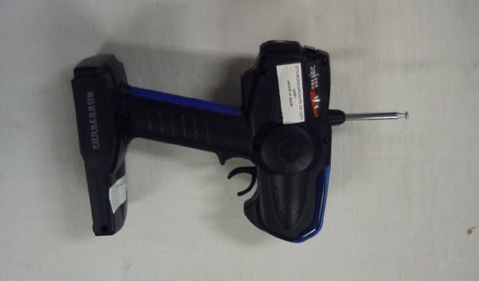
Click to zoom
Application Details
- Equipment Class
- TNB - Licensed Non-Broadcast Station Transmitter
- Date of Grant
- Jul 17, 2003
- Application Purpose
- Original Equipment
- Date of Application
- Jul 17, 2003
- Equipment Note
- REMOTE CONTROL TRANSMITTER
- Frequency Range
- 75.41000000 - 75.99000000
- Company
- Hitec RCD Inc.
- Country
- United States
Documents & Files
Document Text
Text extracted from the exhibit documents filed with the FCC. Open a document above to read the original.
Users Manual
32 Table of Contents Introduction Congratulations on your purchase of the Aggressor FM pistol grip radio system. The Aggressor FM is loaded with many great features to maximum your R/C experience. Please read this manual carefully to familiarize yourself with the operation of your new Aggressor. After reading this manual, store it in a safe place for future reference. - Ergonomically designed 3-Channel Pistol Grip FM Radio - Servo Reversing (Channels 1 & 2) - End Pont Adjustments (EPA) for Steering and Throttle - Dual Rate Steering (Adjustable on the fly) - 3rd Channel push button for shifting - 3 L.E.D. Battery status indicators - Audible power indicator - Removable crystals for easy channel changing (If this is legal in your Country) - Interchangeable rubber grip pads to fit all hand sizes - Assorted colored grip pads and tuning covers for personalizing your radio - Foam steering wheel for comfortable control - Charging Jack for optional rechargeable batteries - 3-CH FM micro receiver - Standard HS-325HB servo - Receiver dry battery holder System Features AGGRESSORAGGRESSOR 3 5 4 6 7 8 1. System Specifications a. Transmitter b. Receiver c. Servo d. Accessories e. Options 2. Transmitter Functions and Operations a. Power Switch b. Battery Indicator LED's c. Steering Dual Rate d. 3rd Channel Push Button e. Steering and Throttle trims f. Tuning Cover g. End Point Adjustments (EPA h. Servo Reversing switches i. Battery Cover j. Antenna k. Grip Pad l. Crystal m. Charging Jack n. Steering Wheel o.Throttle Trigger 3. Transmitter Battery Installation 4. Recharging Batteries 5. Receiver and Servo Connections a. Receiver b. Servos c. Battery 6. Troubleshooting Guide 7. Warnings 8. Racers Tips Product Service Information ( for USA & Canada only ) In the event you would require service to your radios, please send the parts to : Hitec RCD USA, Inc. Service Department 12115 Paine St. Poway, CA 92064 Please include your name address and telephone number along with a brief description of the failure or the work that you are requesting to be done. A) Transmitter: - Current drain 180mA - Modulation: FM - Power supply: 8AA alkaline, Nicad or NiMh batteries - Frequencies: 27mhz (6 channels), 75mhz (30 channels) B) Receiver: - HFS-03MM - Modulations: FM - Power Supply: 4.8V- 6V - Weight: 0.6oz - Size: 1.5 x 1.0 x 0.6" - Current drain: 30mA +/- 0.3mA D) Accessories: - "Brake Pad" This small piece of foam can be attached to the brake lever on the trigger to take up any space between your finger and the lever for a custom fit. E) Options: - Red, Blue and Black colored grip pads in large and small sizes (Sold separately). - Tuning covers available in Red, Blue and Clear, as well as custom designs in Silver Carbon and Camouflage (Sold separately). C) Servo: - HS-325HB - Voltage range: 4.8 - 6V - Speed: 0.15sec/60 degree (6V) - Torque: 51in/oz (6V) - Weight: 1.5oz - Size: 1.6" x 0.8" x 1.4" 1. System Specifications 45 J) Antenna: - Always extend your antenna before turning your transmitter on. - Your antenna may be removed by turning counter clockwise. - Warning: When collapsing your antenna, never push it from the top or it may bend! K) Grip Pad: - The removable grip pad helps keep your hand secure on the handle for better control of the vehicle. - The Grip Pads are also available in assorted colors and sizes to customize the look and feel of your radio. Grip Pad AGGRESSORAGGRESSOR A. Power Switch B. Battery Indicator LED's C. Steering Dual Rate D. 3rd Channel Push Button E. Steering and Throttle trims F. Tuning Cover G. End Point Adjustments H. Servo Reversing switches I. Battery Cover J. Antenna K. Grip Pad L. Crystal M. Charging Jack N. Steering Wheel O. Throttle Trigger Battery Cover E) Steering and Throttle trims: - The trims are used to fine-tune the point where the servo returns to center. - Use the ST-TRIM so your vehicle will go perfectly straight when the steering wheel is centered. If you move the trim to its maximum and the vehicle does not go straight, move the servo horn on the servo output spline or adjust the linkage to fix the problem. Ideally, the servo horn will have equal throw in each direction. - Use the THR-TRIM to adjust the "Drag Brake"; this is the amount of braking that occurs when you let of the trigger. Be aware that too much may affect the servo end point preventing maximum power. Increase the throttle EPA is this happens. - Tip#1: Do not mount the horn on the servo until you turn on the radio and center the trims. - Tip#2: Always trim your vehicle before you run or race. F) Tuning Cover: - Remove the tuning cover to access the servo reversing switches and End Point Adjustments (EPA). - This is also an interchangeable part with assorted colors and designs to choose from so you may customize the look of your radio. See "Option Parts" for more info. G) End Point Adjustments (EPA): - Used to set the servo end points for the steering and throttle. H) Servo Reversing switches: - These are used to change the direction of the servo travel for proper control when activated. - If you steer right and the wheels go left, change the "ST" switch from NOR to REV or REV to NOR if needed. The same applies to the throttle. - (Note: You should not need to change the "THR" switch from NOR if using an Electronic Speed Control.) I) Battery Cover: - Remove to change batteries. ST-EPATHR-EPA LFTRGTTHRBRK NOR - REVNOR - REV STTHR TOP FRONT 2. Transmitter Functions and Operations A) Power Switch: - Slide the switch up to turn on the transmitter, and down to turn it off. - Warning: Always turn your transmitter on before switching on the receiver switch. This will help prevent accidental runaways. B) Battery Indicator LED's: - Green is mid - high power - Amber is mid power (You should replace or charge your batteries very soon.) - Red is low power (Stop driving!) C) Steering Dual Rate: - Adjusts the overall travel of the steering servo. - Push the dial forward with your thumb for maximum steering. - Pull the …
Text truncated - open the document above for the full version.
Operational Description
4 Tuning Procedures 1. Attach 12.0 Vdc power supply 2. Using a Spectrum analyzer and a short-range pick-up antenna, look for 75MHz signal with sufficient scan width to see 30-150 MHz spurious. 3. Adjust T1, T2, T3, T4, and T5 for maximum output at operating frequency and minimum output at any harmonics. 4. Repeat step 6. 5. Check for minimum emissions from 30 to 760 MHz. Inspection Specifications Frequency: FO +1KHz Modulation: 2.8KHz FM RF Power: 400 +/- 50mW Frame Time: 17~21mS General Description The Aggressor is a low power, non-voice, transmitter intended for remote control of ground based models in the 75MHz band. The unit is held with two hands in front of the body. The equipment employs a vertical polarized antenna, directly mounted on the unit and meets Paragraphs 95.645, 95.647, 95.649, and the technical requirements established in the Report & Order in PR Docket 90-222. Circuits and Devices to Stabilize Frequency Transmitter output frequency is determined and stabilized by crystal-controlled oscillator. Circuits to suppress Spurious Radiation Final RF amplifier spurious emissions are attenuated by a “PI” matching network consisting of L2, C18, C19, C23, C17, C13, C14, T1, T2, T3, T4 and T5. Functions of Active Semiconductors Reference Type Function Q2 C1623 Modulator Q6 C2223 Driver/ X-Tal Oscillator Q7 C2223 Driver Q8 C4910 Final Amplifier IC1 ST62T30B Encoder
Parts List/Tune Up Info
5 Chapter 2 Parts list and Schematic Parts list Item Q'ty Comp Name Reference Part SMT PARTS 1 3 CHIP RESISTER J1,J2,J3(157) RC 1/16W 0 ohm 2 1 CHIP RESISTER R1 RC 1/16W 100K 3 2 CHIP RESISTER R19,R2 RC 1/16W 8.2K 4 3 CHIP RESISTER R3,R18,R20 RC 1/16W 220 5 2 CHIP RESISTER R7,R4 RC 1/16W 22 6 4 CHIP RESISTER R5,R33,R34,R36 RC 1/16W 820 7 2 CHIP RESISTER R9,R6 RC 1/16W 18K 8 11 CHIP RESISTER R8,R15,R21,R30,R31, R32, R35,R37,R39,R41,R43 RC 1/16W 1K 9 1 CHIP RESISTER R10 RC 1/16W 6.2K 10 3 CHIP RESISTER R11,R12,R25 RC 1/16W 1.2K 11 3 CHIP RESISTER R13,R40,R42 RC 1/16W 4.7K 12 1 CHIP RESISTER R14 RC 1/16W 3.3K 13 4 CHIP RESISTER R16,R24,R27,R29 RC 1/16W 10K 14 1 CHIP RESISTER R17 RC 1/16W 220K 15 1 CHIP RESISTER R22 RC 1/16W 470 16 1 CHIP RESISTER R23 RC 1/16W 2.2 18 2 CHIP RESISTER R38,R26 RC 1/16W 100 19 1 CHIP RESISTER R28 RC 1/16W 560 20 24 CHIP CAPACITOR C1,C2,C5,C7,C8,C10,C11, C12,C16,C21,C26,C27,C30, C32,C35,C37,C38,C39,C40, C41,C42,C43,C44,C45 CS1608 X7R 103K 21 2 CHIP CAPACITOR C33,C28 CS1608 X7R 102K 22 1 CHIP CAPACITOR C6 CS1608 COG 47P 23 1 CHIP CAPACITOR C13 CS1608 COG 22P 24 1 CHIP CAPACITOR C14 CS1608 COG 20P 25 1 CHIP CAPACITOR C17 CS1608 COG 91P 26 1 CHIP CAPACITOR C18 CS1608 COG 1P 27 1 CHIP CAPACITOR C19 CS1608 COG 33P 6 28 2 CHIP CAPACITOR C22,C24 CS1608 COG 5P 29 1 CHIP CAPACITOR C23 CS1608 COG 56P 30 2 CHIP CAPACITOR C29,C25 CS1608 COG 100P 31 2 CHIP CAPACITOR C31,C36 CS1608 COG 470P 32 1 CHIP CAPACITOR C34 CS1608 COG 150P 33 2 CHIP CAPACITOR C46,C47 CS1608 COG 30P 34 1 CHIP TANTAL C3 ECSTIAY 226KR (22uF/16V) 35 1 CHIP TANTAL C9 ECSTIAY 106KR (10uF/16V) 36 1 CHIP TANTAL C15 ECSTIVY 474KR (0.47uF/16V) 37 3 CHIP DIODE D1,D3,D4 RLS4148 38 1 CHIP ZENNER D2 RLZ 5.1B (5.1V) 39 1 CHIP ZENNER D6 RLZ 6.2B (6.2V) 40 1 VARICAP DIODE D5 BB515G 41 2 CHIP TRANSISTOR Q2,Q4 2SC2223 42 2 CHIP TRANSISTOR Q3,Q5 2SC1623 43 2 CHIP TRANSISTOR Q7,Q6 2SC3900 44 1 CHIP IC U1 NJU7201U50 INSERT PARTS 45 1 CPU IC IC1 ST62T30B 46 1 SLIDE SWITCH SW1 SKS2204 47 2 SLIDE SWITCH SW2,SW3 SSSS-922CNSL4 48 1 TACT SWITCH SW4 STM0611 49 2 VOLUME VR2,VR1 TR133N 10.3F693Z B5K-1253 50 1 SEMI VOLUME VR3 PT6KV-202A (B2K) 51 1 SEMI VOLUME VR4 PT6KV-103A B10K 52 1 VOLUME VR5 V09 V CO 20F B20K 53 2 VOLUME VR6,VR7 V09 H CO 20F B10K 54 4 SEMI VOLUME VR8,VR9,VR10,VR11 EVM 49G A00 B14 (10KB) 55 1 CRYSTAL X1 HTF 75MHz 56 1 CRYSTAL X2 8MHz 57 1 ANTTENA ANT1 HT-7N-R 58 1 PCB FR-1 AGG-FM-M01 59 1 DCJACK CHG1 DCP202-2PIN 60 1 ELEC. CAPACITOR C4 100uF/16V SR 61 1 MYLER CAPACITOR C20 J-TYPE 103(M) 7 62 1 DIODE D7 IN4003 63 1 LED LED1 DL-11S2-ON1 (RED) 64 1 LED LED2 DL-11S2-YN1 (YELLOW) 65 1 LED LED3 DL-11S2-GN1 (GREEN) 66 1 JUMP WIRE L1 0.6 X 4J (4mm) 67 6 JUMP WIRE 0.6 X 10J (10mm) 68 1 INDUCTOR COIL L2 10uH (HDQ-01) 69 1 INDUCTOR COIL L3 LAL03-1.2uH 70 1 PIEZO BUZZER PZ1 EFM-250A 71 1 TRANSISTOR Q1 C4910 72 1 RFT COIL RFT1 HDR05S 73 2 RFT COIL RFT2,RFT3 HDR01S 74 2 RFT COIL RFT5,RFT4 HDR04S 75 3 WAFER WF1,WF2,WF3 PH-3A(8283-3P) 76 2 WAFER WF4,WF5 PH-2A(8283-2P) 77 1 CRYSTAL SOCKET ASS'Y HP-2TS 78 1 WIRE ASS'Y CH1 8283-3P 0.08X30X55MM(HRP) 79 1 WIRE ASS'Y CH2 8283-3P 0.08X30X95MM(HRP) 80 1 WIRE ASS'Y DUAL RATE 8283-3P 0.08X30X180MM(HRP) 81 1 WIRE ASS'Y CH3 8283-2P 0.08X30X100MM(HRP) 82 1 WIRE ASS'Y BATT 8283-2P 0.08X30X240MM(HRP)
Parts List/Tune Up Info
4 Tuning Procedures 1. Attach 12.0 Vdc power supply 2. Using a Spectrum analyzer and a short-range pick-up antenna, look for 75MHz signal with sufficient scan width to see 30-150 MHz spurious. 3. Adjust T1, T2, T3, T4, and T5 for maximum output at operating frequency and minimum output at any harmonics. 4. Repeat step 6. 5. Check for minimum emissions from 30 to 760 MHz. Inspection Specifications Frequency: FO +1KHz Modulation: 2.8KHz FM RF Power: 1 mW Frame Time: 17~21mS General Description The Aggressor is a low power, non-voice, transmitter intended for remote control of ground based models in the 75MHz band. The unit is held with two hands in front of the body. The equipment employs a vertical polarized antenna, directly mounted on the unit and meets Paragraphs 95.645, 95.647, 95.649, and the technical requirements established in the Report & Order in PR Docket 90-222. Circuits and Devices to Stabilize Frequency Transmitter output frequency is determined and stabilized by crystal-controlled oscillator. Circuits to suppress Spurious Radiation Final RF amplifier spurious emissions are attenuated by a “PI” matching network consisting of L2, C18, C19, C23, C17, C13, C14, T1, T2, T3, T4 and T5. Functions of Active Semiconductors Reference Type Function Q2 C1623 Modulator Q6 C2223 Driver/ X-Tal Oscillator Q7 C2223 Driver Q8 C4910 Final Amplifier IC1 ST62T30B Encoder
Test Report
APPLICANT: HITEC RCD INC. FCC ID: IFHAGGRESSOR-F75 REPORT #: H\HITEC\489ZUT3\489ZUT3TestReport.doc TABLE OF CONTENTS TABLE OF CONTENTS LIST APPLICANT: HITEC RCD INC. FCC ID: IFHAGGRESSOR-F75 TEST REPORT: PAGE 1......COVER SHEET - GENERAL INFORMATION & TECHNICAL DESCR. PAGE 2......TECHNICAL DESCRIP. CONTINUED. & RF POWER OUTPUT PAGE 3......MODULATION CHARACTERISTICS AND OCCUPIED BANDWIDTH PAGE 4......OCCUPIED BANDWIDTH PLOT PAGE 5......OCCUPIED BANDWIDTH PLOT - CW PAGE 6......FIELD STRENGTH OF SPURIOUS EMISSION PAGE 7......METHOD OF MEASURING RADIATED SPURIOUS EMISSIONS PAGE 8......FREQUENCY STABILITY PAGE 9-12...TEST EQUIPMENT LIST EXHIBIT CONTAINING: EXHIBIT 1..........FCC ID LABEL SAMPLE & LOCATION EXHIBIT 2..........EXTERNAL PHOTOGRAPHS EXHIBIT 3..........INTERNAL PHOTOGRAPHS EXHIBIT 4..........BLOCK DIAGRAM EXHIBIT 5..........SCHEMATIC EXHIBIT 5..........USER'S MANUAL EXHIBIT 6..........CIRCUIT DESCRIPTION EXHIBIT 7..........TUNING PROCEDURE EXHIBIT 8..........TEST SET UP PHOTO APPLICANT: HITEC RCD INC. FCC ID: IFHAGGRESSOR-F75 REPORT #: H\HITEC\489ZUT3\489ZUT3TestReport.doc Page 1 of 12 GENERAL INFORMATION 2.1033(c)(1)(2) HITEC RCD INC. will sell the FCCID: IFHAGGRESSOR-F75 Radio Control transmitter in quantity, for use PART 95 SUBPART C. HITEC RCD INC. 12115 PAINE STREET POWAY CA 92064 2.1033(c)(3) Instruction manual is included as exhibit #6. 2.1033 (4) Type of Emission: 8K0F1D 95.631(b)(1) Bn = 2M + 2DK M = 4,800 Bits per second D = 800 Hz (Peak Deviation) K = 1 Bn = 2(4800/2) + 2(800)(1) = 4.8K + 3.2K = 8.0k ALLOWED AUTHORIZED BANDWIDTH = 8.00 kHz. 95.631(b) Authorized Bandwidth 8 kHz for RC Transmitter 2.1033(c)(5) Frequency Range: 75.01-75.99 MHz 95.623(a) (6) Power Range and Controls: There are NO user Power controls. (6) Function of each electron tube or semiconductor device or other active circuit device: See Exhibit #7. (7) Maximum Output Power Rating: 0.00094 W ERP. (8) DC Voltages and Current into Final Amplifier: FINAL AMPLIFIER ONLY Vce = 12.0Volts DC Ice = 0.039A. Pin = 0.5Watts 2.1033(c)(9) Tune-up procedure. The tune-up procedure is included as Exhibit #8. APPLICANT: HITEC RCD INC. FCC ID: IFHAGGRESSOR-F75 REPORT #: H\HITEC\489ZUT3\489ZUT3TestReport.doc Page 2 of 12 2.1033(c)(10) Complete Circuit Diagrams: The circuit diagram is included as part of Exhibit # 5. (10) Description of all circuitry and devices provided for determining and stabilizing frequency is given in EXHIBIT #7. 2.1033(c)(11) The Equipment identification is shown as Exhibit #1. 2.1033(c)(12) Photographs of the equipment are shown as Exhibits No. 2-3. 2.1033(c)(13) Equipment employing Digital modulation. N/A. 2.1033(c)(14) The data required by 2.1046-2.1057 follows; 2.1046 RF power is measured by the ERP METHOD. There is no provisions to limit the power. With a nominal battery voltage of 12.0 VDC, and the transmitter properly adjusted the RF output measures: Po = 0.00094 Watts ERP 2.1046 RF power output. HP Spectrum Analyzer TRANSMITTER UNDER TEST WITH INTERNAL ANTENNA 3.0 meters SIGNAL DIPOLE Tuned, Calibrated GENERATOR ANTENNA Antenna which may be raised from 1 to 4 meters above ground and changed in polarization Equipment placed 80 cm. above ground on a rotatable platform. APPLICANT: HITEC RCD INC. FCC ID: IFHAGGRESSOR-F75 REPORT #: H\HITEC\489ZUT3\489ZUT3TestReport.doc Page 3 of 12 2.1047 Modulation characteristics: AUDIO FREQUENCY RESPONSE The Voice is NOT allowed in this band. 2.1049 Occupied bandwidth: 95.635(b) (1) At least 25dB on any frequency removed from the center of the authorized bandwidth by more than 50% up to and including 100% of the authorized bandwidth. (10) At least 45 dB on any frequency removed from the center of the authorized bandwidth by more than 100% up to and including 125% of the authorized bandwidth. (11) At least 55 dB on any frequency removed from the center of the authorized bandwidth by more than 125% up to and including 250% of the authorized bandwidth. (12) At least 56 + 10 log 10 (T) dB on any frequency removed from the center of the authorized bandwidth by more than 250%. Radiotelephone transmitter with modulation limiter. Test procedure diagram OCCUPIED BANDWIDTH MEASUREMENT Coupler Transmitter 50 ohm under test Resistive Wattmeter Audio Spectrum Oscillator Analyzer APPLICANT: HITEC RCD INC. FCC ID: IFHAGGRESSOR-F75 REPORT #: H\HITEC\489ZUT3\489ZUT3TestReport.doc Page 4 of 12 OCCUPIED BANDWIDTH PLOT APPLICANT: HITEC RCD INC. FCC ID: IFHAGGRESSOR-F75 REPORT #: H\HITEC\489ZUT3\489ZUT3TestReport.doc Page 5 of 12 2.1051 SPURIOUS EMISSIONS AT ANTENNA TERMINALS. NOT APPLICABLE, NO antenna port. This UUT has a permanently attached antenna. 2.1053 UNWANTED RADIATION: 95.635(1)(3)(7)(10)(11)(12) REQUIREMENTS: At least 56 + 10log(T) on any frequency removed from the center of the authorized bandwidth by more than 250%. 56 + 10log(0.00094) = 26 dB TEST DATA: Emission Frequency MHz dBc dBm 75.42 0 -0.3 150.82 42 -42 226.22 39 -39 301.62 42 -42 377.02 51 -51 452.42 56 -56 527.82 47 -47 603.22 40 -40 678.62 38 -38 754.20 40 -40 METHOD OF MEASUREMENT: The procedure used was C63.4-1992. The unit was operating into its permanently attached antenna at a height of 80 cm. The spectrum was scanned from 30 to at least the tenth harmonic of the fundamental using a HP model 8566B spectrum analyzer and an appropriate antenna. Measurements were made at the open field test site of TIMCO ENGINEERING INC. located at 849 N.W. State Road 45 Newberry, FL 32669. APPLICANT: HITEC RCD INC. FCC ID: IFHAGGRESSOR-F75 REPORT #: H\HITEC\489ZUT3\489ZUT3TestReport.doc Page 6 of 12 Method of Measuring Radiated Spurious Emissions Hewlett Packard Spectrum Analyzer HP8566B TRANSMITTER _____ INTEGRAL ANTENNA UNDER TEST <- 3.0m > Tuned, Calibrated Antenna which may be raised from 1m to 4m above ground POWER SUPPLY and changed in polarization Equipment placed 80cm above ground on a rotatable platform. APPLICANT: HITEC RCD INC. FCC ID: IFHAGGRESSOR-F75 REPORT #: H\HITEC\489ZUT3\489ZUT3TestReport.doc Page 7 o…
Text truncated - open the document above for the full version.
Contact Information
Applicant
Tony Ohm(Service Dept. Manager)
Test Firm
Timco Engineering, Inc.S Sanders
Technical Specifications
| # | Rule Parts | Frequency Range | Power Output | Emission | Tolerance |
|---|---|---|---|---|---|
| 1 | 95C | 75.41 MHz - 75.99 MHz | 940.00 µW | 8K00F1D | 20.0000000000 ppm |
Other Applications from Hitec RCD Inc.
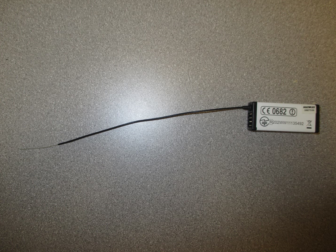
IFHRX57MLINK
Dec 22, 20147 CHANNEL 2.4 GHz TRANSCEIVER
Equipment Class
DSS - Part 15 Spread Spectrum Transmitter
IFHRX5MLINK
Dec 16, 2014RX5 M-LINK CHANNEL 2.4 GHz TRANSCEIVER
Equipment Class
DXX - Part 15 Low Power Communication Device Transmitter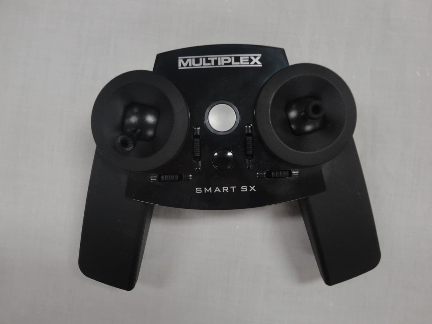
IFHSMART-SX
Sep 16, 20146 CHANNEL 2.4 GHz RADIO CONTROL TRANSMITTER
Equipment Class
DSS - Part 15 Spread Spectrum Transmitter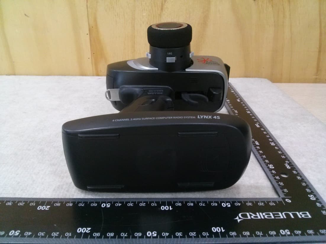
IFHLYNX4S
Jul 22, 20142.4GHz Radio Control System
Equipment Class
DSS - Part 15 Spread Spectrum Transmitter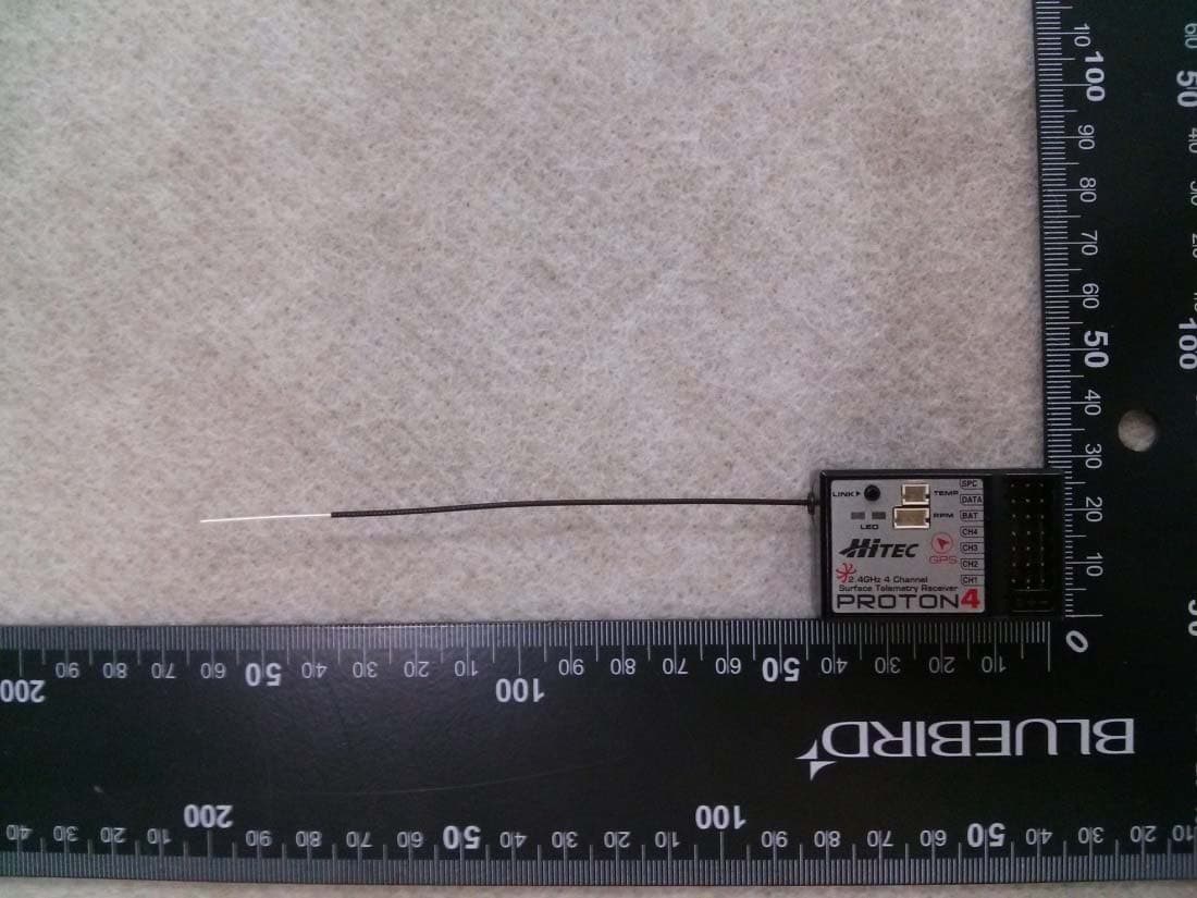
IFHPROTON4
Jul 22, 20142.4GHz Radio Control System
Equipment Class
DSS - Part 15 Spread Spectrum Transmitter