IFHLYNX4S2.4GHz Radio Control System
Hitec RCD Inc.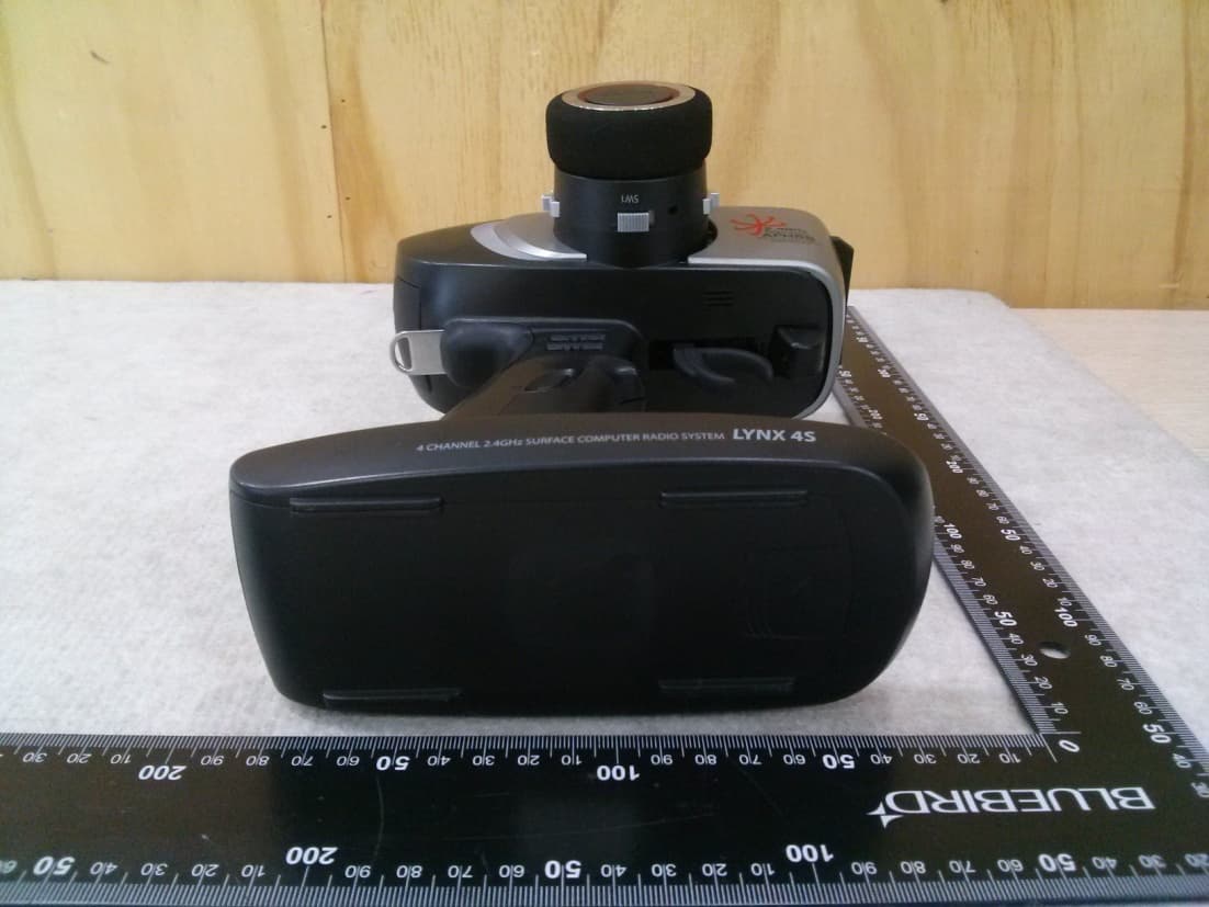
Click to zoom
Application Details
- Equipment Class
- DSS - Part 15 Spread Spectrum Transmitter
- Date of Grant
- Jul 22, 2014
- Application Purpose
- Original Equipment
- Date of Application
- Jul 22, 2014
- Equipment Note
- 2.4GHz Radio Control System
- Frequency Range
- 2409.20000000 - 2474.00000000
- Company
- Hitec RCD Inc.
- Country
- United States
Documents & Files
Document Text
Text extracted from the exhibit documents filed with the FCC. Open a document above to read the original.
Users Manual
Intro. Thank you for purchasing the LYNX 4S transmitter. LYNX 4S is co mposed of diverse features to maximize customer’s R/C experienc es. Please read carefully to become familiar with LYNX 4S under your control. A fter reading this, please keep this manual for easy reference. Product Specifications - Frequency Range : 2.4092GHz~2.474GHz - Modulation : Frequency Hopping Spread Spectrum (FHSS) - Tx Power : Max. 100mW - Channel : 109Ch(random 21 ch among 109 ch) - Operating Temperature : -10°C ~ +50°C - Power : 4.8VDC Features - 4096 Resolution - Intenna Surface FHSS 2.4GHz - HHR (HITEC HIGH Resolution) SYSTEM 4ms (ONLY AXION 2) - Backlight Graphic LCD Screen - Six Colors LED(RED/GREEN/BLUE/YELLOW/MAGENTA/CYAN) - CAR / Boat / 4WD / Crawler Channel Mixing - Spring Tension Control(Steering / Throttle) - Three step Mixing Switch - Steering / Throttle Gimbal ballbearing - Vibration motor Warning Mode - Music play Mode(ONLY wav file) - Warning voice file(ONLY wav file) - Two-way Telemetry(RPM , SPEED , TEMP , VOLT) - Micro SD - 30 – Model Memory(Micro SD - Add 30 memory, Total 60 memory) - 12 letter model name - Easy Left-hander change Mode - PC link and Upgrade - Earphone connection - Extension Mountain Mode - Various Battery Compatibility(Lipo / Life / NiMH / NiCD) Transceiver Binding(ID setting) <TX> 1. Power ON_(Get off down SW_ Displayed in the upper right corner of the screen, you must hav e a RF.) 2. Dial SW press once(Go to the menu screen.) 3. Dial SW keep turning down the SYSTEM menu. 4. RX-BIND Position the cursor in the menu, press the Dial SW.(Go to the RX-BIND screen.) 5. RX-MODEL Dial SW Position the cursor on by pressing Receiver, s o you can choose the right move the cursor. 6. AXION 2 Position the cursor, press ESC on. (Go to the RX-MODEL. ) 7. Dial SW Turn down the the START position 8. START is pressed, the LED color will change BINDING runs. <Dial SW> <RX> 1. RX-click the Link button on the power (4.8V) is applied to the link SW release. 2. RX intersection Blinks the LED on the end of the BLUE color. 3. The power OFF and then ON. <TX> 9. RX and press ESC SW BINDING is complete. 10. For about 5 seconds, then press ESC SW twice more, go to the ma in menu screen. (Warning – Available LINK range of Tx and Rx is between 45cm a nd 5M. If LINK cut off more than 1 second because of the extern al environment in the Scan Mode or one of transceiver’s power is t urned off, you have to turn off both the Tx and Rx then LINK ag ain.) Servo Monitor Mode(TX and RX are available in the state BINDING ) 1. From the main screen, press the Dial SW, entry menu screen. 2. Dial SW keep turning down the SYSTEM menu. 3. SERVO menu, position the cursor, press the Dial SW. (Go to the MONITOR screen.) 4. Dial SW Lift up again, go to the TEST menu, press the Dial SW. (Go to the Speed adjustment menu.) 5. Dial SW by turning the variable speed servo (up to make it fast er.) 6. ESC twice while pressing the stop menu. Transmitter Scan Mode 1. LYNX 4S Power ON, Move to SYSTEM TAB. 2. RX-SCAN Menu button entered will appear asking if you want to s can. "You will run a scan is it? Then all you need to rebind RX! " 3. YES by pressing SCAN is executed. 4. Process again after complete to BINDING of the transceiver. Fail safe and hold mode When Rx signal take effect on external influence if you set the Fail - safe mode, the servo will go to Fail–safe position you stored already. The servo will turn off the power for 1 second in hold time if you didn’t enable the Fail–safe mode. Then the servo will keep no-load co ndition and move to the position that is ordered last time until it detects a normal si gnal again. Always, the Fail-safe mode must be enable for safe flight and the Fail-safe mode is required safe flight status like the engine idling, the motor stop, extended air brake, etc. - Fail-safe set-up 1. After the transmitter power ON SET 1/2 TAB to select the FAILSA FE. 2. If you select SET on each channel can be set as the FAILSAFE mo de. 3. ST & TH moves and the number at the bottom of the current value is displayed. 4. After setting the desired value, press SET to save the value. 5. May set the value stored for each channel by pressing the SEND Data is sent to the receiver. 6. Once the receiver is receiving Data ON after the power is turne d OFF. 7. Check the servo move to the Fail-safe position. - Fail-safe Setting TEST 1. The flight move to the any place that is not the Fail-safe sett ing. 2. It is the normal Fail-safe setting if the servo moves to the Fa il-safe position you set lastly after you turn off the Tx. - The way to re-enable the Hold mode in Fail-safe mode. 1. After the transmitter power ON SET 1/2 TAB to select the FAILSA FE. 2. Each channel is HOLD selected, HOLD mode can be set. 3. ST & TH moves and the number at the bottom of the current value is displayed. 4. After setting the desired value, press SET to save the value. 5. May set the value stored for each channel by pressing the SEND Data is sent to the receiver. 6. Once the receiver is receiving Data ON after the power is turne d OFF. 7. Check the servo move to the Fail-safe position. (Warning – The Fail-safe setting will delete you set lastly i f the Fail-safe mode is disabled. Always check the Fail-safe mo de work normally before you turn on the engine or motor.) Low Battery Warning - The battery voltage is normal, there is no change in the module . - The battery voltage is low, the alarm sounds. Please check the battery voltage immediately if you here a beep in flight. Range Check Please check the range for verifying that transceiver operate n ormally. (Warning – Transceiver Pre-set the ID for user’s convenience wh en it comes from factory.) Warnings and Precautions - Don’t steer this in the busy street. - Don’t steer this in the rain and on the standing water. - Don’t steer this after drink alcohol. - Always check the remaining battery power. - Always power on the Tx first then power on the Rx next to preve nt failure. WARNING & SAFETY…
Text truncated - open the document above for the full version.
Cover Letter(s)
HITEC RCD INC. 12115 Paine Street, Poway, California, 92064 United States Tel. 858-748-8440 / Fax. 858-748-1767 Date: June 18, 2014 To: SIEMIC, INC. 775 Montague Expressway, Milpitas, CA 95035 USA Dear Sir/Madam, Re: Project and Product Certification Representative Authorization Letter We, Hitec RCD Inc., hereby authorize SIEMIC, INC. to act as a Certification Body for certifying for the following project : - Product : 2.4GHz Radio Control System - Model name : LYNX 4S - FCC ID : IFHLYNX4S We affirm that between SIEMIC and Hitec RCD Inc., any difference in understanding, including test plan, measurement methods, applicable standards and relevant procedures and processes have been resolved prior to commencement of testing activities. I, the undersigned, hereby certify that we are not subject to a denial of federal benefits, that includes FCC benefits, pursuant to Section 5301 of the Anti-Drug Abuse Act of 1988, 21 U.S.C. 853(a). This authorization is valid until further written notice from the applicant. Sincerely Yours, ______________________________________ Tony Ohm /Manager, Service Dept. /Hitec RCD Inc.
Cover Letter(s)
HITEC RCD INC. 12115 Paine Street, Poway, California, 92064 United States Tel. 858-748-8440 / Fax. 858-748-1767 FCC Confidentiality Request Letter Date: June 18, 2014 Federal Communications Commission Authorization and Evaluation Division 7435 Oakland Mills Road Columbia MD 21046 Subject: Permanent Confidentiality Request for FCC ID: IFHLYNX4S We hereby request confidential treatment of information accompanying this application as outlined below: Block diagram Schematics Operation Description The above materials contain trade secrets and proprietary information not customarily released to the public. The public disclosure of these materials may be harmful to the applicant and provide unjustified benefits to its competitors. The applicant understands that pursuant to Section 0.457 & 0.459 of the Rules, disclosure of this application and all accompanying documentation will not be made before the date of the Grant for this application. Sincerely Yours, ______________________________________ Tony Ohm /Manager, Service Dept. /Hitec RCD Inc.
External Photos
External photos of EUT
ID Label/Location Info
<LYNX 4S Certification Label Design> <Label Location> Label location
Internal Photos
Internal photos of EUT Antenna
RF Exposure Info
http://www.emc2000.co.kr EMC compliance Ltd. Page: 1 of 1 65, Sinwon-ro, Yeongtong-gu, Suwon- si, Gyeonggi-do, 443-390, Korea 82-31-336-9919 (Main) 82-505-299-8311 (Fax) This test report shall not be reproduced except in full, Without the written approval. * RF Exposure 1. Regulation According to §15.247(i), systems operating under the provisions of this section shall be operated in a manner that ensures that the public is not exposed to radio frequency energy levels in excess of the Commission's guidelines. See § 1.1307(b)(1) of this Chapter. Limits for Maximum Permissive Exposure: RF exposure is calculated. Frequency Range Electric Field Strength [V/m] Magnetic Field Strength [A/m] Power Density [㎽/㎠] Av er ag ing Time [minute] Limits for General Population / Uncontrolled Exposure 0.3 ~ 1.34 614 1.63 *(100) 30 1.34 ~ 30 824 /f 2.19/f *(180/f 2 ) 30 30 ~ 300 27.5 0.073 0.2 30 300 ~ 1500 / / f/1500 30 1500 ~ 15000 / / 1.0 30 f=frequency in ㎒, *= plane-wave equivalent power density MPE (Maximum Permissive Exposure) Prediction Predication of MPE limit at a given distance: Equation from page 18 of OET Bulletin 65, Edition 97 - 01 SPGRRPGS4 4 2 S=power density [㎽/㎠] P=Power input to antenna [㎽] G=Power gain of the antenna in the direction of interest relative to an isotropic radiator R= distance to the center of radiation of the antenna [㎝] EUT: Maximum peak output power = 29.17 [㎽](= 14.65 ㏈m) Antenna gain= 1.73(= 2.39 [㏈i]) 100 ㎽, at 20 cm from an antenna 6 [㏈i] S = PG/4πR² = 100 × 3.98 / (4 × π × 400) = 0.079 18 [㎽/㎠] < 1.0 [㎽/㎠] 20.00 ㎽, at 20 cm from an antenna 2.39 [㏈i] S = PG/4πR²= 0.010 06 [㎽/㎠] < 1.0 [㎽/㎠] 20.00 ㎽, at 2.5 cm from an antenna 2.39 [㏈i] S = PG/4πR²= 0.644 04 [㎽/㎠] < 1.0 [㎽/㎠] 2. RF Exposure Compliance Issue The information should be included in the user’s manual: This appliance and its antenna must not be co-located or operation in conjunction with any other antenna or transmitter. A minimum separation distance of 20 ㎝ must be maintained between the antenna and the person for this appliance to satisfy the RF exposure requirements.
Test Report
http://www.emc2000.co.kr FCC/IC TEST REPORT Report No.: EMC-FCC-R0173 EMC compliance Ltd. Page: 1 of 49 65, Sinwon-ro, Yeongtong-gu, Suwon- si, Gyeonggi-do, 443-390, Korea 82-31-336-9919 (Main) 82-505-299-8311 (Fax) This test report shall not be reproduced except in full, Without the written approval. FCC/IC TEST REPORT Test report No.: EMC- FCC- R0173 FCC ID: IFHLYNX4S IC: 3420A-LYNX4S Type of equipment: 2.4GHz Radio Control System Basic Model Name: LYNX 4S Applicant: Hitec RCD Inc. Max.RF Output Power: 14.65 ㏈m FCC Rule Part(s): FCC Part 15 Subpart C 15.247 IC Rule: RSS-210, RSS-GEN Frequency Range: 2 409.2 ㎒ ~ 2 474.0 ㎒ Test result: Complied The above equipment was tested by EMC compliance Testing Laboratory for compliance with the requirements of FCC Rules and Regulations. The results of testing in this report apply to the product/system which was tested only. Other similar equipment will not necessarily produce the same results due to production tolerance and measurement uncertainties. Date of receipt: 2014. 06. 18 Date of test: 2014. 06. 30 ~ 07.02 Issued date: 2014. 07. 16 Tested by: AHN, BYUNG WOO Approved by: YU, SANG HOON http://www.emc2000.co.kr FCC/IC TEST REPORT Report No.: EMC-FCC-R0173 EMC compliance Ltd. Page: 2 of 49 65, Sinwon-ro, Yeongtong-gu, Suwon- si, Gyeonggi-do, 443-390, Korea 82-31-336-9919 (Main) 82-505-299-8311 (Fax) This test report shall not be reproduced except in full, Without the written approval. [ Contents ] 1. Client information ............................................................................................................................. 3 2. Laboratory information .................................................................................................................... 4 3. Description of E.U.T. ......................................................................................................................... 5 3.1 Basic description ........................................................................................................................... 5 3.2 General description ....................................................................................................................... 5 3.3 Test frequency ............................................................................................................................... 6 3.4 Test Voltage ................................................................................................................................... 6 4. Summary of test results ..................................................................................................................... 7 4.1 Standards & results ....................................................................................................................... 7 4.2 Uncertainty .................................................................................................................................... 7 5. Test results .......................................................................................................................................... 8 5.1 Antenna Requirement .................................................................................................................... 8 5.2 Maximum Peak Output Power ...................................................................................................... 9 5.3 Carrier Frequency Separation ..................................................................................................... 13 5.4 20 dB Channel Bandwidth .......................................................................................................... 17 5.5 Number of Hopping Channels .................................................................................................... 23 5.6 Time of Occupancy(Dwell Time) ................................................................................................ 27 5.7 Spurious Emission, Band edge, and Restricted bands ................................................................ 31 5.8 Conducted Emission ................................................................................................................... 46 6. Test equipment used for test ........................................................................................................... 49 http://www.emc2000.co.kr FCC/IC TEST REPORT Report No.: EMC-FCC-R0173 EMC compliance Ltd. Page: 3 of 49 65, Sinwon-ro, Yeongtong-gu, Suwon- si, Gyeonggi-do, 443-390, Korea 82-31-336-9919 (Main) 82-505-299-8311 (Fax) This test report shall not be reproduced except in full, Without the written approval. 1. Client information Applicant: Hitec RCD Inc. Address: 12115 Paine Street, Poway, California, 92064 USA Telephone number: 858-748-6948 Facsimile number: 858-748-1767 Contact person: Tony Ohm / [email protected] Manufacturer: Hitec RCD PHILIPPINES, INC. Address: Lot 6 and 8 Blk. 24, Phase 4 CEPZ, Rosario, Cavite, Philippines http://www.emc2000.co.kr FCC/IC TEST REPORT Report No.: EMC-FCC-R0173 EMC compliance Ltd. Page: 4 of 49 65, Sinwon-ro, Yeongtong-gu, Suwon- si, Gyeonggi-do, 443-390, Korea 82-31-336-9919 (Main) 82-505-299-8311 (Fax) This test report shall not be reproduced except in full, Without the written approval. 2. Laboratory information Address EMC compliance Ltd. 65, Sinwon-ro, Yeongtong-gu, Suwon- si, Gyeonggi-do, 443-390, Korea Telephone Number: 82-31-336-9919 Facsimile Number: 82-505-299-8311 Certificate KOLAS No.: 231 FCC Site Registration No.: 687132 VCCI Site Registration No.: R-3327, G-198, C-3706, T-1849 IC Site Registration No.:8035A-2 SITE MAP EMC Compliance Ltd. Suwon city http://www.emc2000.co.kr FCC/IC TEST REPORT Report No.: EMC-FCC-R0173 EMC compliance Ltd. Page: 5 of 49 65, Sinwon-ro, Yeongtong-gu, Suwon- si, Gyeonggi-do, 443-390, Korea 82-31-336-9919 (Main) 82-505-299-8311 (Fax) This test report shall not be reproduced except in full, Without the written approval. 3. Description of E.U.T. 3.1 Basic descriptio…
Text truncated - open the document above for the full version.
Test Setup Photos
http://www.emc2000.co.kr EMC compliance Ltd. Page: 1 of 2 65, Sinwon-ro, Yeongtong-gu, Suwon- si, Gyeonggi-do, 443-390, Korea 82-31-336-9919 (Main) 82-505-299-8311 (Fax) This test report shall not be reproduced except in full, Without the written approval. Te s t setup photos Radiated Emission * 9 ㎑ ~ 30 ㎒ * 30 ㎒ ~ 1 ㎓ http://www.emc2000.co.kr EMC compliance Ltd. Page: 2 of 2 65, Sinwon-ro, Yeongtong-gu, Suwon- si, Gyeonggi-do, 443-390, Korea 82-31-336-9919 (Main) 82-505-299-8311 (Fax) This test report shall not be reproduced except in full, Without the written approval. * 1 ㎓ Over *Conducted Emission
Contact Information
Applicant
Tony Ohm(Service Dept. Manager)
Test Firm
EMC Compliance Ltdchangmin kim
Technical Specifications
| # | Rule Parts | Frequency Range | Power Output |
|---|---|---|---|
| 1 | 15C | 2.41 GHz - 2.47 GHz | 29.00 mW |
Other Applications from Hitec RCD Inc.
IFHRX57MLINK
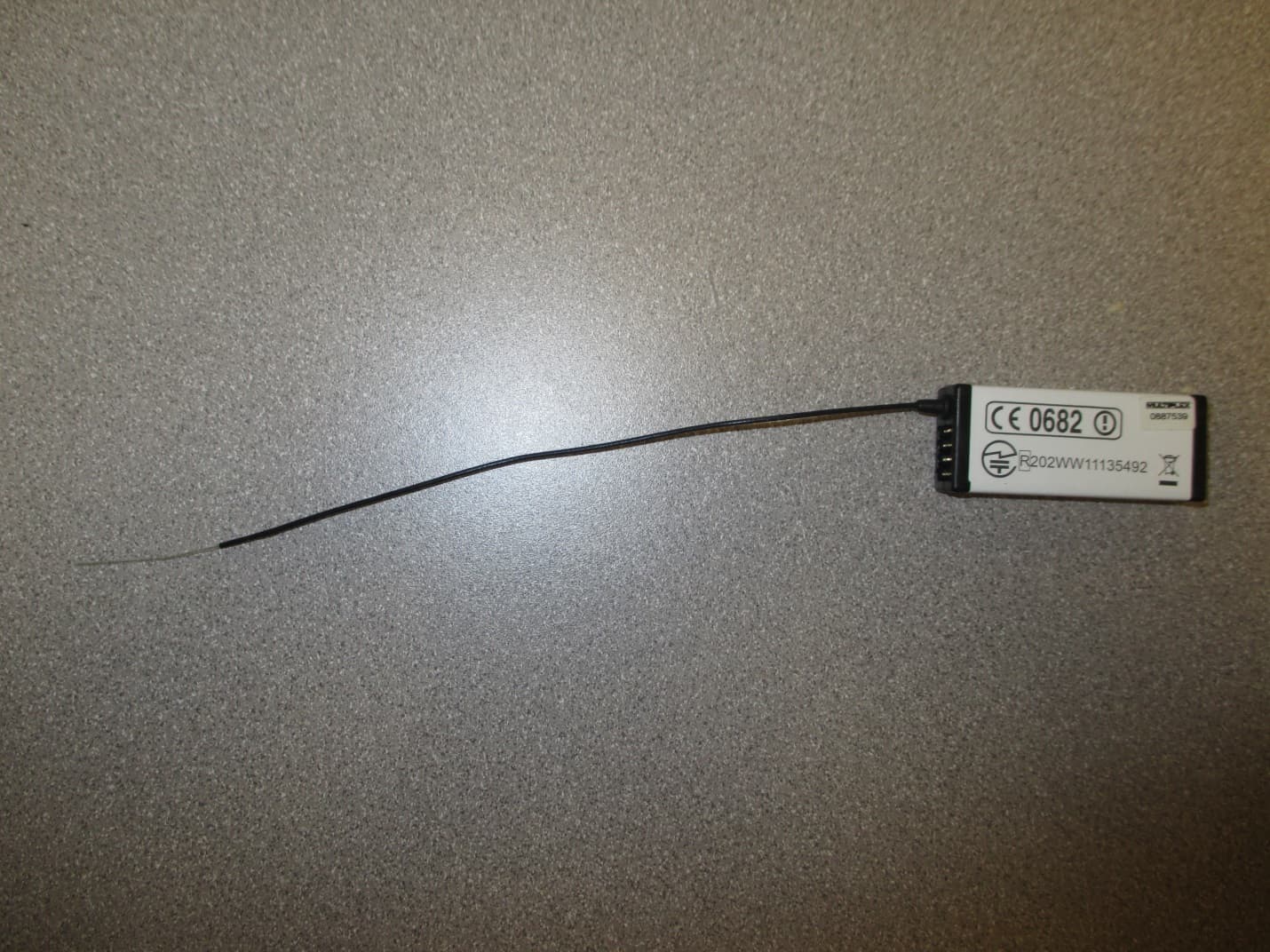
Dec 22, 20147 CHANNEL 2.4 GHz TRANSCEIVER
Equipment Class
DSS - Part 15 Spread Spectrum Transmitter
IFHRX5MLINK
Dec 16, 2014RX5 M-LINK CHANNEL 2.4 GHz TRANSCEIVER
Equipment Class
DXX - Part 15 Low Power Communication Device Transmitter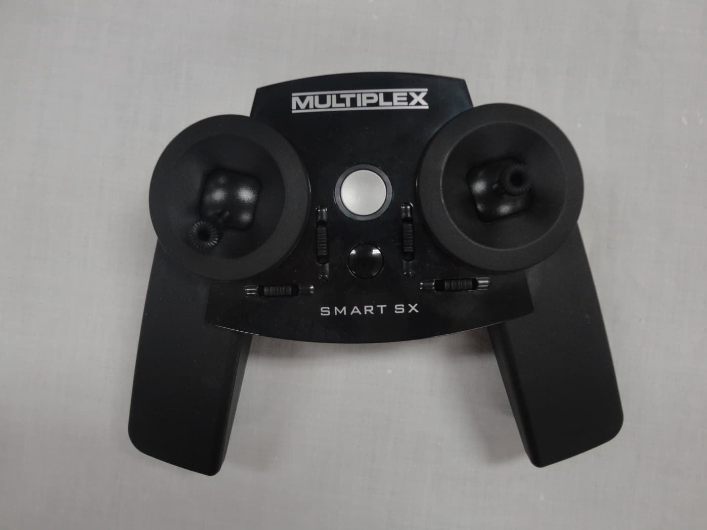
IFHSMART-SX
Sep 16, 20146 CHANNEL 2.4 GHz RADIO CONTROL TRANSMITTER
Equipment Class
DSS - Part 15 Spread Spectrum Transmitter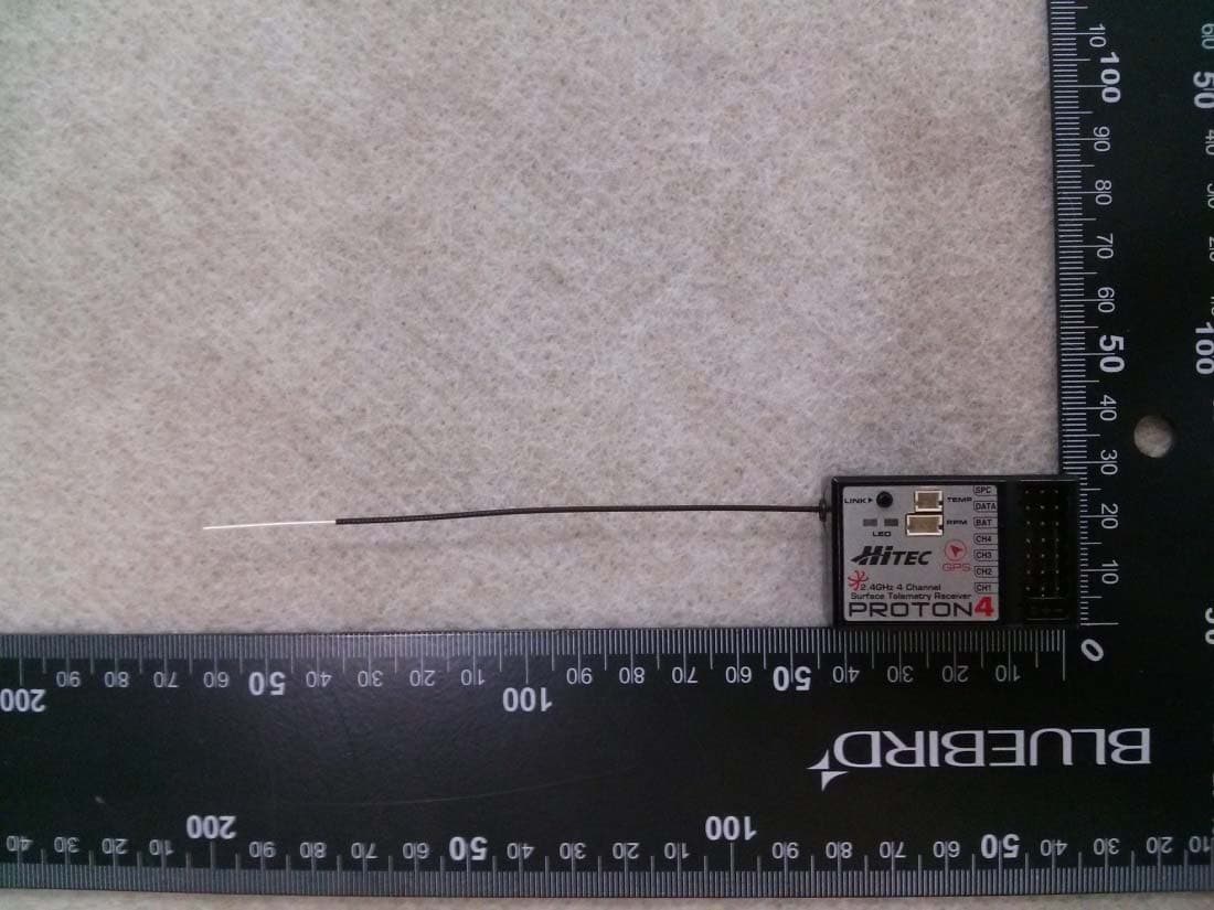
IFHPROTON4
Jul 22, 20142.4GHz Radio Control System
Equipment Class
DSS - Part 15 Spread Spectrum Transmitter
IFHAURORA9X
Aug 19, 20132.4GHz RADIO CONTROL SYSTEM
Equipment Class
DSS - Part 15 Spread Spectrum Transmitter