IFHSMART-SX6 CHANNEL 2.4 GHz RADIO CONTROL TRANSMITTER
Hitec RCD Inc.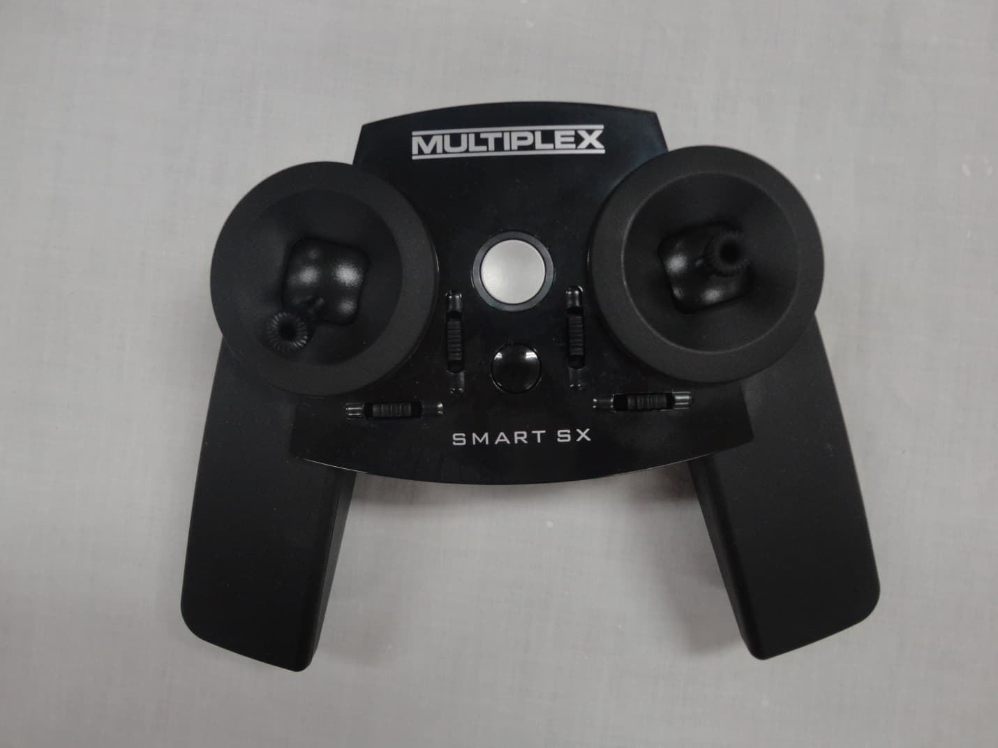
Click to zoom
Application Details
- Equipment Class
- DSS - Part 15 Spread Spectrum Transmitter
- Date of Grant
- Sep 16, 2014
- Application Purpose
- Original Equipment
- Date of Application
- Sep 16, 2014
- Equipment Note
- 6 CHANNEL 2.4 GHz RADIO CONTROL TRANSMITTER
- Frequency Range
- 2402.00000000 - 2472.00000000
- Company
- Hitec RCD Inc.
- Country
- United States
Documents & Files
Document Text
Text extracted from the exhibit documents filed with the FCC. Open a document above to read the original.
Users Manual
SMART SX _________________________________________________________________________________________________________ Page 16 SMART SX instructions # 985 5 3 35 (18.07.2014 TL) • Errors and omissions excepted • © MULTIPLEX 1. CONTENTS 1. Contents 16 2. Quick-Start 16 3. Introduction 17 3.1 The SMART SX philosophy 17 3.2 Features of the SMART SX 17 4. Safety notes, other information 18 5. Set contents / Accessories 20 6. Specification 20 6.1 SMART SX transmitter 20 6.2 RX-5 light M-LINK receiver 21 7. Handling 21 7.1 Transmitter controls 21 7.2 Receiver controls 21 7.3 Transmitter aerial 21 7.4 Inserting dry / rechargeable cells 22 7.5 Voltage monitor / operating times 22 7.6 Binding 22 7.7 Channel assignment 22 7.8 Mode switching 23 7.9 Servo reverse 23 7.10 Unlocking, activating and disabling the throttle function 23 7.11 Trims 24 7.12 Dual Rates 24 7.13 Fail-Safe 24 7.14 Auxiliary (AUX) channel 24 7.15 Range checking 24 7.16 Model memory (ID) 24 7.17 Installing the receiver in the model 26 7.18 The SMART SX as Pupil transmitter 26 7.19 Firmware update / settings for future RR+ models 26 7.20 Installing aluminium sticks 26 7.21 Speech output of telemetry data 27 8. Advice and Service 27 9. Care and Maintenance 27 10. CE Conformity Declarations 27 11. FFC Warning Statements 27 12. IC Warning Statements 27 13. Guarantee / Liability Exclusion 27 14. Disposal 28 15. Fault-finding 28 Congratulations on purchasing your new radio control system. We are delighted that you have selected the MULTIPLEX SMART SX M-LINK. You are now the owner of a superb system for the newcomer to the hobby of radio-controlled modelling. We hope you have many hours of fun and success with your new equipment. 2. QUICK-START 1. Unpack the transmitter and receiver Store the documents safely. 2. Insert the batteries It is essential to maintain cor- rect polarity (see adjacent illus- tration). Reversed polarity may ruin the transmitter and / or the cells. 3. Binding • Preparing the model When binding is complete, the receiving system immediately starts operating. Secure the model carefully so that no damage can result if the propel- ler should start turning. • Prepare the transmitter Hold the multi-function button pressed in and switch the transmitter on, then release the button again. The LED flashes at a high rate. • Prepare the receiver Switch the receiver on with the SET button held pressed in; the receiver LED now flashes at a high rate. If binding is successful, both LEDs revert to a slow flashing rate. 4. Check the directions of servo rotation • Model with ID receiver The transmitter emits an audible signal when it de- tects the receiver. No further adjustments are re- quired. • Model with normal M-Link receiver (light or teleme- try) All the control surfaces (servos) must respond to the sticks in the correct direction; check and re- verse the servos if necessary: move the correct stick to one end-point and hold the multi-function button pressed in for three seconds: the ser- vo now reverses, and moves to the opposite end-point. 5. Carry out a range check It is important to check radio range before the first flight: hold the multi-function but- ton pressed in for two sec- onds immediately after switching on, and the LED glows constantly. The transmitter now generates great- ly reduced power, and emits an audible warning signal. SMART SX _________________________________________________________________________________________________________ Page 17 SMART SX instructions # 985 5 3 35 (18.07.2014 TL) • Errors and omissions excepted • © MULTIPLEX In this mode the control system must continue to function up to a distance of about fifty metres. 6. Flying the model These few steps are all you need to do before the first flight. Be sure to keep to the correct se- quence of switching on and off: always switch the transmitter on first, and only then the receiving system; reverse the sequence when switching off. Before you launch and fly your model please read through the manufacturer’s notes; those concern- ing safety and other warnings are particularly im- portant. 3. INTRODUCTION These operating instructions are an integ-ral part of the product, and contain important information and safety notes. Please store them in a safe place, and be sure to pass them on to the new owner if you ever dispose of the equipment. 3.1 The SMART SX philosophy The SMART SX M-LINK is a compact, intelligent six- channel beginners’ radio control system with a concept for the future! The SMART SX intelligent beginners’ radio control system is fully compatible with other MULTIPLEX sys- tems, from the telemetry-capable COCKPIT SX right up to the high-end PROFI TX system. The same ap- plies to the small ID receiver supplied in the set, which even works with the sophisticated PROFI TX transmit- ter. However, MULTIPLEX offers much more than this: our range also includes a carefully considered, con- sistent series of models. Our complete RTF (Ready- to-Fly) packages contain the model, factory-assem- bled and almost ready for the air, the SMART SX transmitter, an RX-5 M-LINK ID receiver, dry cells, a rechargeable flight battery and a 230 V battery charger. Once you have unpacked the model, all you have to do is attach the wings, charge the flight pack and receiver battery (if used), and prepare the trans- mitter. When these few procedures are out of the way, there is nothing to stop you flying the model. The presence of the M-LINK ID receiver enables the SMART SX to detect the specific model, and automatically activate the as- sociated settings from its enor- mous reserve of model memo- ries: fifty independent model memories are available. All compatible MULTIPLEX ELAPOR® models from RR+ to RTF are programmed in the transmitter as standard. Many models from other manufacturers can be fitted with an ID receiver, and this makes it very simple for the intelligent SMART SX transmitter to detect each ID receiver, and ex- ploit its advantages. The overall conce…
Text truncated - open the document above for the full version.
External Photos
APPLICANT: HITEC RCD INC. FCC ID: IFHSMART-SX EXTERNAL PHOTOS
ID Label/Location Info
ID:IFHSMART-SX 3420A-SMARTSX
Internal Photos
Smart SX PCB TOP Smart SX PCB BOTTOM
Test Report
TEST REPORT PER FCC PT 15.247 AND IC RSS-210 ISSUE 8 FHSS APPLICANT HITEC RCD INC. ADDRESS 12115 PAINE STREET POWAY CALIFORNIA 92064 USA FCC ID IFHSMART-SX IC 3420A-SMARTSX MODELS Smart SX PRODUCT DESCRIPTION 6 CH 2.4GHz RADIO CONTROL TRANSMITTER DATE SAMPLE RECEIVED 6/16/2014 DATE TESTED 9/5/2014 TESTED BY Cory Leverett APPROVED BY Sid Sanders REPORT ISSUE DATE 9/8/2014 TIMCO REPORT NO. 1011AUT14TestReportRev1.docx TEST RESULTS PASS FAIL THE ATTACHED REPORT SHALL NOT BE REPRODUCED EXCEPT IN FULL WITHOUT THE WRITTEN APPROVAL OF TIMCO ENGINEERING, INC. 849 NW STATE ROAD 45 NEWBERRY, FL 32669 USA PH: 888.472.2424 OR 352.472.5500 FAX: 352.472.2030 EMAIL: [email protected] HTTP://WWW.TIMCOENGR.COM TABLE OF CONTENTS EUT DESCRIPTION ................................................................................................................... 5 ANTENNA REQUIREMENTS ........................................................................................................ 6 §15.203 Antenna requirement. ............................................................................................. 6 §15.204 Antenna modifications. ............................................................................................ 7 §15.247 FHSS Technical requirements ....................................................................................... 8 Section 15.247(a) ................................................................................................................. 8 Section 15.247(g): ................................................................................................................ 9 Section 15.247(h):................................................................................................................ 9 Pseudorandom Frequency Hopping Sequence ..........................................................................10 Equal Hopping Frequency Use................................................................................................10 De Facto EIRP Limit ..............................................................................................................10 Point-to-Point Operation .......................................................................................................10 System Receiver Input Bandwidth ..........................................................................................11 System Receiver Hopping Capability .......................................................................................11 TEST PROCEDURES .................................................................................................................12 Conducted Testing Procedures ...............................................................................................12 Radiated Testing Procedures .................................................................................................15 CONDUCTED TESTING RESULTS: ..............................................................................................16 Conducted RF power: ...........................................................................................................17 Hopping Channels ................................................................................................................18 Hops per Channel ................................................................................................................19 Channel dwell time per hop ...................................................................................................20 20 dB Occupied Bandwidth ....................................................................................................21 99% Power Occupied Bandwidth ............................................................................................22 Carrier Channel Separation ...................................................................................................23 Low Band Edge with Hopping Stopped @ Lowest Channel Used in Band ......................................24 Low Band Edge with Hopping On ............................................................................................25 High Band Edge with Hopping Stopped @ Highest Channel Used in Band ....................................26 High Band Edge with Hopping On ...........................................................................................27 RADIATED TESTING RESULTS: .................................................................................................29 Radiated RF power: ..............................................................................................................29 Field Strength Lower Restricted Band Hopping On Vertical ........................................................31 Field Strength Lower Restricted Band Hopping On Horizontal .....................................................32 Field Strength Upper Restricted Band Hopping On Vertical ........................................................33 Field Strength Upper Restricted Band Hopping On Horizontal .....................................................34 Field Strength Lower Restricted Band Hopping Stopped Vertical .................................................35 Field Strength Lower Restricted Band Hopping Stopped Horizontal .............................................36 Field Strength Upper Restricted Band Hopping Stopped Vertical .................................................37 Field Strength Upper Restricted Band Hopping Stopped Horizontal .............................................38 Test Setup Photos ...................................................................................................................39 EUT Photos ............................................................................................................................41 EMC EQUIPMENT LIST .............................................................................................................47 APPLICANT: HITEC RCD INC. F…
Text truncated - open the document above for the full version.
Test Setup Photos
APPLICANT: HITEC RCD INC. FCC ID: IFHSMART-SX TEST SET UP PHOTOS
Contact Information
Applicant
Tony Ohm(Service Dept. Manager)
Technical Contact
Timco Engineering, Inc.Cory Leverett
[email protected]888-472-2424
849 NW State Road 45 · NEWBERRY, Florida · United States
Non-Technical Contact
Timco Engineering, Inc.Sharon Hoffman
[email protected]888-472-2424
Test Firm
Timco Engineering, Inc.Bruno Clavier
Technical Specifications
| # | Rule Parts | Frequency Range | Power Output |
|---|---|---|---|
| 1 | 15C | 2.40 GHz - 2.47 GHz | 50.00 mW |
Other Applications from Hitec RCD Inc.
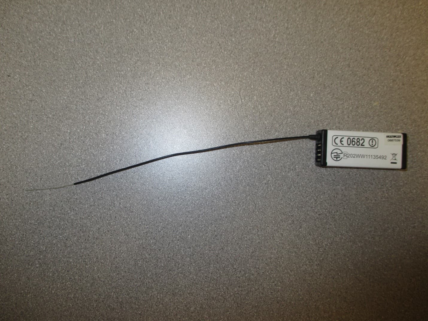
IFHRX57MLINK
Dec 22, 20147 CHANNEL 2.4 GHz TRANSCEIVER
Equipment Class
DSS - Part 15 Spread Spectrum Transmitter
IFHRX5MLINK
Dec 16, 2014RX5 M-LINK CHANNEL 2.4 GHz TRANSCEIVER
Equipment Class
DXX - Part 15 Low Power Communication Device Transmitter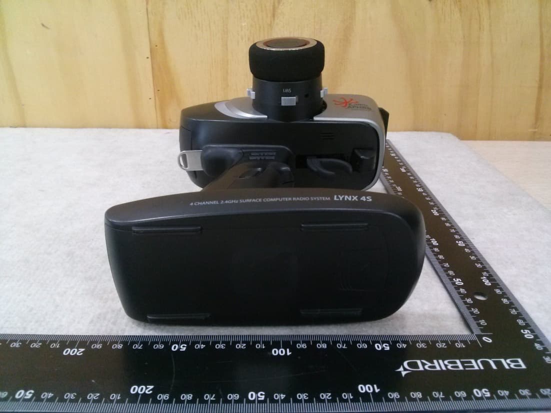
IFHLYNX4S
Jul 22, 20142.4GHz Radio Control System
Equipment Class
DSS - Part 15 Spread Spectrum Transmitter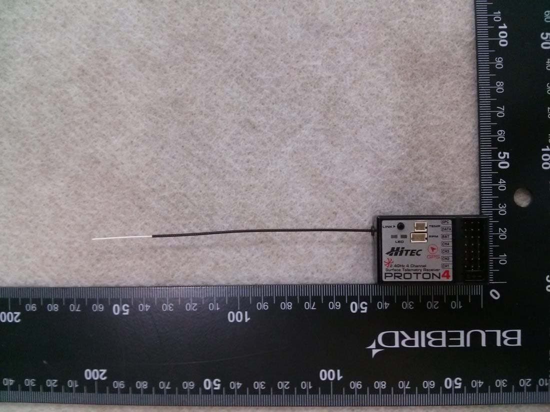
IFHPROTON4
Jul 22, 20142.4GHz Radio Control System
Equipment Class
DSS - Part 15 Spread Spectrum Transmitter
IFHAURORA9X
Aug 19, 20132.4GHz RADIO CONTROL SYSTEM
Equipment Class
DSS - Part 15 Spread Spectrum Transmitter