IFHRX5MLINKRX5 M-LINK CHANNEL 2.4 GHz TRANSCEIVER
Hitec RCD Inc.
Click to zoom
Application Details
- Equipment Class
- DXX - Part 15 Low Power Communication Device Transmitter
- Date of Grant
- Dec 16, 2014
- Application Purpose
- Original Equipment
- Date of Application
- Dec 16, 2014
- Equipment Note
- RX5 M-LINK CHANNEL 2.4 GHz TRANSCEIVER
- Frequency Range
- 2402.00000000 - 2479.00000000
- Company
- Hitec RCD Inc.
- Country
- United States
Documents & Files
Document Text
Text extracted from the exhibit documents filed with the FCC. Open a document above to read the original.
Users Manual
Operating Instructions RX-5 light M-LINK 2.4 GHz receiver MULTIPLEX Modellsport GmbH & Co.KG • Westliche Gewerbestraße 1 • D-75015 Bretten (Gölshausen) • www.multiplex-rc.de Page 1/4 Instructions: RX-5 light M-LINK 2.4 GHz receiver # 985 5316 (10-01-08/MIWA) • Errors and omissions excepted! • © MULTIPLEX ! These operating instructions are an integral part of the product, and contain important information and safety notes. Please store them in a safe place, where you can find them at any time, and pass them on to the new owner if you sell the receiver. 1. SPECIFICATION RX-5 light M-LINK Order No. # 5 5808 Reception system 2.4 GHz FHSS M-LINK Frequency Hopping Spread Spectrum MULTIPLEX-LINK Servo channel count 5 Servo signal frame rate Fast response: 14 ms Standard: 21 ms (according to transmitter) Signal resolution 12-bit, 3872 steps (according to transmitter) Current drain approx. 30 mA (excl. servos) Aerial feed length / aerial length Feed cable: approx. 10 cm Aerial: approx. 3 cm Operating voltage 3.5 V ... 9.0 V Î 4 - 6 NiCd / NiMH cells (NiXX) Î 2S LiPo / LiIo Operating temperature range - 20 °C ... + 55 °C Weight 7 g Dimensions approx. 34.0 x 19.5 x 11.0 mm 2. SPECIAL FEATURES • Small, all-purpose 5-channel receiver exploiting MULTIPLEX 2.4 GHz M-LINK technology, ideal for use in small models. • In-line connector arrangement: Ideal for use even in slender fuselages. • HOLD / FAIL-SAFE function. • Integral SET button and LED: For binding, FAIL-SAFE programming, RESET and operating status information. 3. SAFETY NOTES ! Please read the instructions before using the receiver. ! Use the receiver only for the intended applications (Î 4.). ! Ensure the power supply is of adequate capacity (Î 6.). ! Observe the installation notes (Î 9.). ! Carry out regular range checks (Î 10.). 4. APPLICATION The RX-5 light M-LINK is a radio control receiver intended exclusively for use in model sport applications. It is prohibited to use it for other applications, such as man-carrying vehicles or industrial installations. The RX-5 light M-LINK was designed with minimum possible size and weight as top priority, and for technical reasons such a unit cannot offer the same reception characteristics as a larger, technically more sophisticated and more expensive receiver. In the interests of safety we recommend that you use a larger receiver wherever space permits. Under normal conditions it is certainly possible to obtain excellent reception characteristics with a small receiver such as the RX-5 light M-LINK provided that all the RC system components are carefully arranged, and the receiver aerial correctly deployed. 5. COMPATIBILITY The RX-5 light M-LINK 2.4 GHz receiver can only be used in conjunction with transmitters which use MULTIPLEX M-LINK transmission technology. As of January 2010 these are: • ROYALpro 7, 9 and 16 M-LINK. • ROYALevo or pro 7, 9 and 12 with firmware version V3.xx and the HFM4 M-LINK 2.4 GHz RF module. • PROFImc 3010, 3030 and 4000 with the HFM3 M-LINK 2.4 GHz RF module. • COCKPIT SX M-LINK. • MULTIPLEX transmitters with the HFMx M-LINK 2.4 GHz RF module. 6. POWER SUPPLY The RX-5 light M-LINK receiver works with a wide range of voltages from 3.5 V ... 9.0 V, i.e. with receiver batteries con- sisting of 4 to 6 NiXX cells or 2S LiPo / 2S LiIo batteries. ! Note: if you wish to use a five-cell (six-cell) NiXX battery, check that all the servos, gyros and other components to be connected to the system are approved by the manufacturer for use on operating voltages up to 7.5 V (9.0 V). If you wish to use a 2S LiPo (2S LiIo) pack, check that all the servos, gyros and other components to be connected to the system are approved by the manufacturer for use on up to 8.4 V (8.2 V). ! Note: ensure that the power supply is adequate A power supply system in good condition and of adequate capacity for the specific application plays an indispensable role in the safe operation of any model: • Use only high-quality receiver batteries of adequate capacity. Balance and maintain them carefully, and charge them fully. • Ensure that all cables are of adequate conductor cross- section. Keep all wiring as short as possible, and use the absolute minimum of plug / socket connections. • Use high-quality switch harnesses exclusively. • Brief collapses in the power supply voltage (lasting a few milli-seconds) have no adverse effect on the receiver. Longer voltage collapses to below 3.5 V may cause a receiver reset, resulting in a brief interruption in reception. This may be due to a receiver battery which is almost flat, too weak or defec- tive, cables of inadequate cross-section, poor-quality con- nectors or an overloaded or defective BEC system. Operating Instructions RX-5 light M-LINK 2.4 GHz receiver MULTIPLEX Modellsport GmbH & Co.KG • Westliche Gewerbestraße 1 • D-75015 Bretten (Gölshausen) • www.multiplex-rc.de Page 2/4 Instructions: RX-5 light M-LINK 2.4 GHz receiver # 985 5316 (10-01-08/MIWA) • Errors and omissions excepted! • © MULTIPLEX 7. RECEIVER CONNECTIONS This receiver employs the UNI connector system, which is com- patible with the connector systems used by most radio control manufacturers (e.g. HiTEC, robbe/Futaba, Graupner/JR). The receiver sockets are marked as follows: 1, 2, 3, 4, 5 Servo sockets, channel 1, 2, 3, 4, 5. ! Note: a separate receiver battery can be connected to all five servo sockets (1 ... 5). ! When connecting the receiver battery, servos, speed controllers ... it is essential to ensure that the con-nectors are plugged in correctly, and feature compatible pin assign- ments: (see symbol on the receiver)! 8. FIRST USE, FUNCTIONS 8.1 LED codes LED code Description LED Code 0 LED OFF Battery voltage too low LED Code 1 LED ON No reception LED Code 2 1,6 sec Binding process running 1,6 sec LED Code 3 Normal reception in progress 1,6 sec LED Code 5 Confirmation signal 8.2 Binding Before it can be used, the receiver must be linked to the trans- mitter using the process known as “binding”.…
Text truncated - open the document above for the full version.
External Photos
APPLICANT: HITEC RCD INC. FCC ID: IFHRX5MLINK EXTERNAL PHOTOS
ID Label/Location Info
3402A-RX5MLINK RX-5 M-Link ID
ID Label/Location Info
3402A-RX5MLINK
ID Label/Location Info
3402A-RX5MLINK RX-4/9 Flexx
Internal Photos
Date: 2012-09-27 MPX-No.: 4094210 M --- ® LA anlöten der stiftleiste RX5 en.dsf RX-5 light M-Link Contact PCB Assembly 2. contact PCB - Header touches the PCB edge - Attention: solder it at right angles with the PCB RX-5 light M-Link mounting the assembled PCB, header and contact PCB 1. soldering header --> PCB soldering the upper pins soldering a pin or a piece of wire contact PCB --> main PCB After the assembly the programming of the receiver has to be made. Please refer to test instruction No. 20056 for RX-5 light M-Link / RX-5 M-Link ID CONFIDENTIAL
Test Report
FCC PART 15.249 & IC RSS-210 (i8) ANNEX A2.9 UNLICENSED INTENTIONAL RADIATOR COMBINED TEST REPORT APPLICANT HITEC RCD INC. ADDRESS 12115 PAINE STREET POWAY CALIFORNIA 92064 USA FCC ID IFHRX5MLINK IC 3420A-RX5MLINK MODELS RX-5 light, RX-5 M-Link ID, RX-4/9 Flexx PRODUCT DESCRIPTION RX5 M-LINK 2.4 GHZ TRANSCEIVER DATE SAMPLE RECEIVED 9/23/2014 DATE TESTED 12/2/2014 TESTED BY Cory Leverett APPROVED BY Sid Sanders REPORT ISSUE DATE 12/10/2014 TIMCO REPORT NO. 1718AUT14TestReport.docx TEST RESULTS PASS FAIL THE ATTACHED REPORT SHALL NOT BE REPRODUCED EXCEPT IN FULL WITHOUT THE WRITTEN APPROVAL OF TIMCO ENGINEERING, INC. 849 NW State Road 45 Newberry, FL 32669 USA Ph: 888.472.2424 or 352.472.5500 Fax: 352.472.2030 Email: [email protected] Website: www.timcoengr.com APPLICANT: HITEC RCD INC. FCC ID: IFHRX5MLINK IC: 3420A-RX5MLINK REPORT: H\HITEC_IFH\1718AUT14\1718AUT14TestReport.docx Page 2 of 13 Table of Contents GENERAL REMARKS ...................................................................................................... 3 GENERAL INFORMATION ................................................................................................ 4 TEST RESULTS SUMMARY .............................................................................................. 4 TEST PROCEDURES ....................................................................................................... 5 RADIATION INTERFERENCE ............................................................................................ 6 BANDEDGE .................................................................................................................. 8 BANDEDGE .................................................................................................................. 9 SPURIOUS EMISSIONS INTO ADJACENT RESTRICTED BAND ............................................. 10 POWER LINE CONDUCTED INTERFERENCE ...................................................................... 12 EMC EQUIPMENT LIST .................................................................................................. 13 APPLICANT: HITEC RCD INC. FCC ID: IFHRX5MLINK IC: 3420A-RX5MLINK REPORT: H\HITEC_IFH\1718AUT14\1718AUT14TestReport.docx Page 3 of 13 GENERAL REMARKS The attached report shall not be reproduced except in full without the written permission of Timco Engineering Inc. Summary The device under test does: fulfill the general approval requirements as identified in this test report not fulfill the general approval requirements as identified in this test report Attestations This equipment has been tested in accordance with the standards identified in this test report. To the best of my knowledge and belief, these tests were performed using the measurement procedures described in this report. All instrumentation and accessories used to test products for compliance to the indicated standards are calibrated regularly in accordance with ISO 17025: 2005 requirements. I attest that the necessary measurements were made, under my supervision, at: Timco Engineering Inc. 849 NW State Road 45 Newberry, Fl 32669 Authorized Signatory Name: Cory Leverett Project Manager Date: 12/10/2014 Table of Contents APPLICANT: HITEC RCD INC. FCC ID: IFHRX5MLINK IC: 3420A-RX5MLINK REPORT: H\HITEC_IFH\1718AUT14\1718AUT14TestReport.docx Page 4 of 13 GENERAL INFORMATION EUT Specification The test results relate only to the items tested. Applicable Standards FCC Part 15.249 & IC RSS-210 (i8), RSS-GEN (i4) EUT Description 2.4 GHz transciever FCC ID IFHRX5MLINK IC Certification Number 3420A-RX5MLINK Model Number RX-5 light, RX-5 M-Link ID, RX-4/9 Flexx Operating Frequency TX: 2402 MHz RX: FHSS 2402-2479 MHz No. of Channels 39 Modulations TX: CQPSK (bind only) RX: FHSS EUT Power Source 110–120Vac/50– 60Hz when Charging DC Power Battery Operated Exclusively Test Item Prototype Pre- Production Production Type of Equipment Fixed Mobile Portable Antenna Connector FCC Rules require that the antenna connector be unique. There is no antenna connector, it has an integrated PCB antenna Test Facility Timco Engineering Inc. located at 849 NW State Road 45 Newberry, FL 32669 USA. Conditions in the Test laboratory Temperature: 24-26ºC Relative humidity: 50-65% Test Exercise For transmitter test a sample was programmed to transmit a modulated signal at 100% duty cycle. This was done at the only channel in the band Revision History of EUT None TEST RESULTS SUMMARY FCC Rules Part No. Industry Canada Rules RESULTS – Pass/Fail/NA 15.249 Fundamental Emission RSS-210 (i8) ANNEX A2.9, RSS-GEN (i4) Pass 15.249 & 15.209 Harmonics & Spurious RSS-210 (i8) ANNEX A2.9, RSS-GEN (i4) Pass 15.205 & 2.202 Occupied Bandwidth RSS-GEN (i4), 4.6 Pass 15.249 & 15.205 Bandedge Compliance RSS-GEN (i4), 4.6 Pass 15.207 Power Line Emissions RSS-GEN (i4), 7.2.4 NA Table of Contents APPLICANT: HITEC RCD INC. FCC ID: IFHRX5MLINK IC: 3420A-RX5MLINK REPORT: H\HITEC_IFH\1718AUT14\1718AUT14TestReport.docx Page 5 of 13 TEST PROCEDURES Radiation Interference: ANSI C63.4-2003 using a spectrum analyzer, a preselector, a quasi-peak adapter, and an appropriate antenna. The analyzer was calibrated in dB above a microvolt at the output of the antenna. The resolution bandwidth was 100 kHz with an appropriate sweep speed and the video bandwidth was 300 kHz up to 1 GHz and 1 MHz with a video BW of 3 MHz above 1 GHz. When an emission was found, the table was rotated to produce the maximum signal strength. The antenna was placed in both the horizontal and vertical planes and the worst case emissions were reported. The spectrum was searched to at least the tenth (10) harmonic of the fundamental. Emissions were scanned from 30MHz to the tenth harmonic of the fundamental frequency at three places in the band. All emissions greater than 20 dB from the limit are not reported. Formula Of Conversion Factors: The field strength at 3m was established by adding the meter reading of the spectrum analyzer (which is set to read in units of dBu…
Text truncated - open the document above for the full version.
Test Setup Photos
APPLICANT: HITEC RCD INC. FCC ID: IFHRX5MLINK TEST SET UP PHOTOS
Contact Information
Applicant
Tony Ohm(Service Dept. Manager)
Technical Contact
Timco Engineering, Inc.Cory Leverett
[email protected]888-472-2424
849 NW State Road 45 · Newberry, Florida · United States
Non-Technical Contact
Timco Engineering, Inc.Sharon Hoffman
[email protected]888-472-2424
Test Firm
Timco Engineering, Inc.Bruno Clavier
Technical Specifications
| # | Rule Parts | Frequency Range | Power Output |
|---|---|---|---|
| 1 | 15C | 2.40 GHz - 2.48 GHz | - |
Other Applications from Hitec RCD Inc.
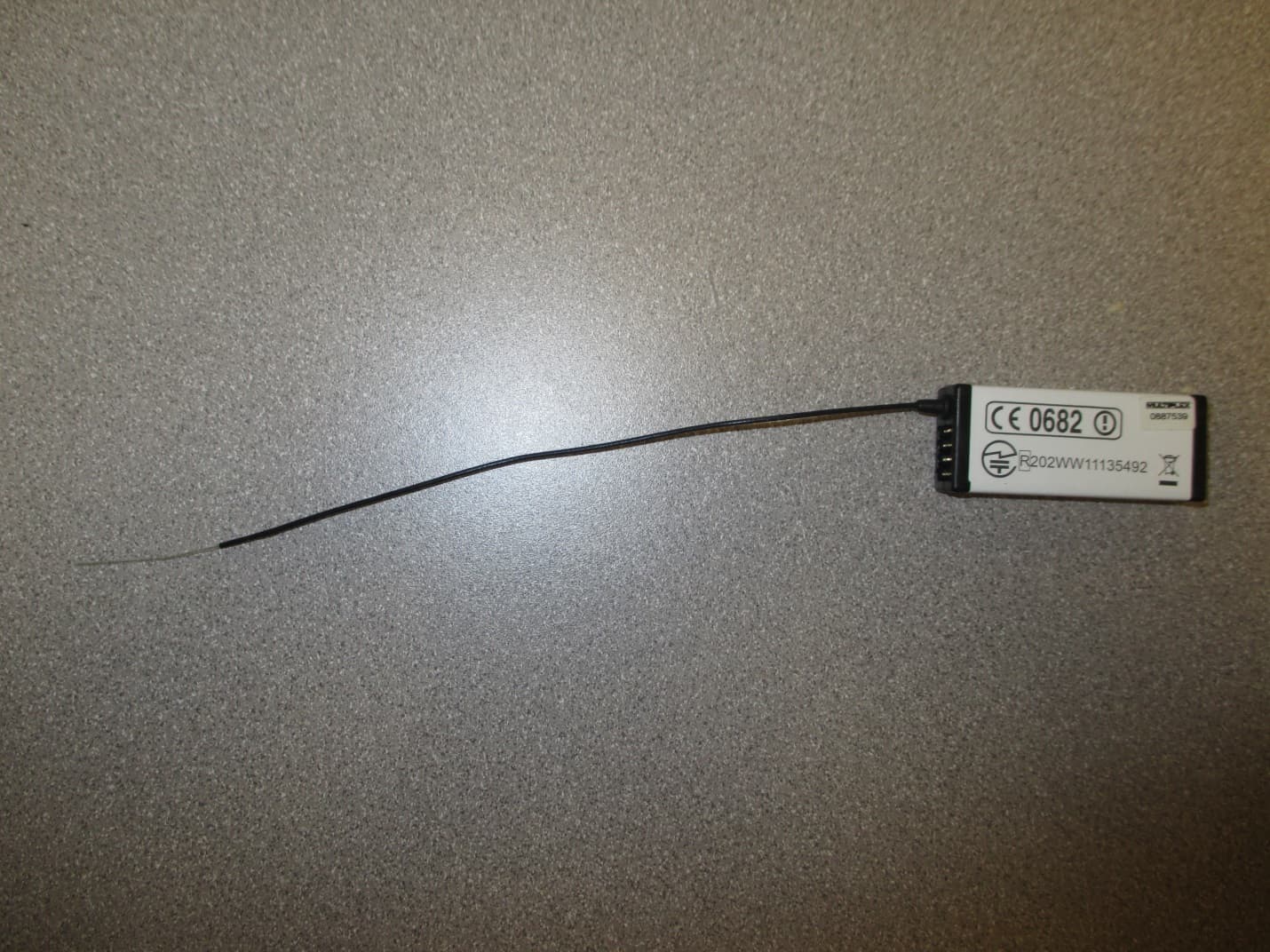
IFHRX57MLINK
Dec 22, 20147 CHANNEL 2.4 GHz TRANSCEIVER
Equipment Class
DSS - Part 15 Spread Spectrum Transmitter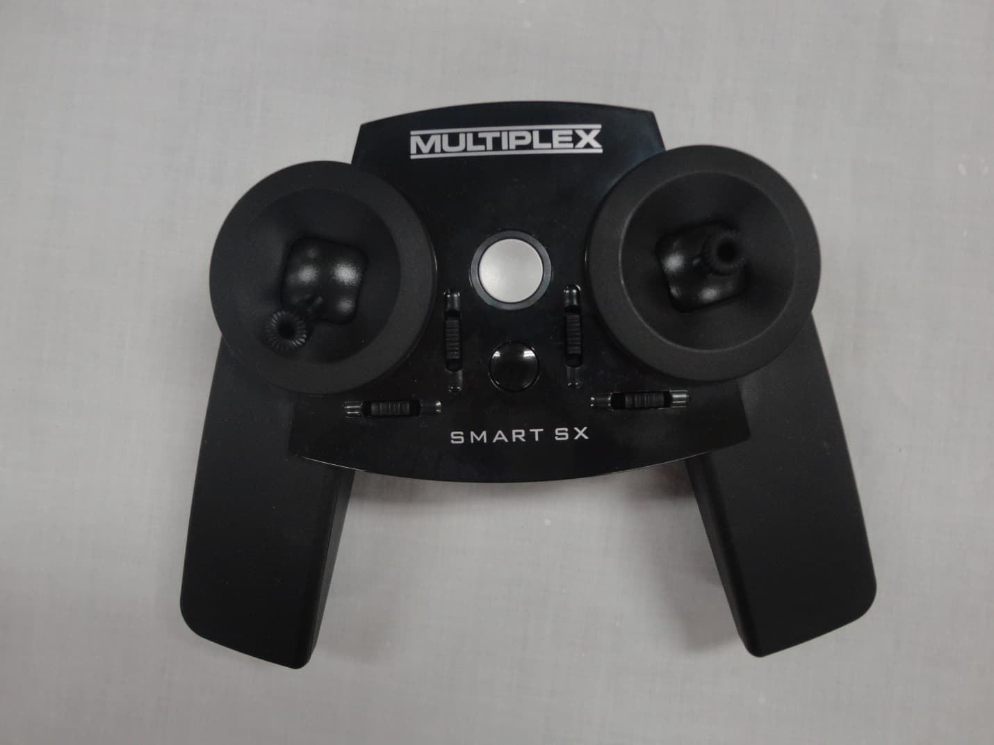
IFHSMART-SX
Sep 16, 20146 CHANNEL 2.4 GHz RADIO CONTROL TRANSMITTER
Equipment Class
DSS - Part 15 Spread Spectrum Transmitter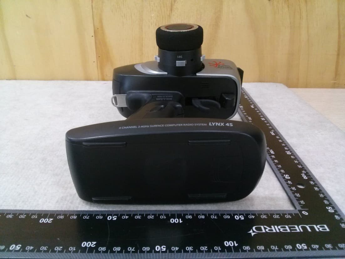
IFHLYNX4S
Jul 22, 20142.4GHz Radio Control System
Equipment Class
DSS - Part 15 Spread Spectrum Transmitter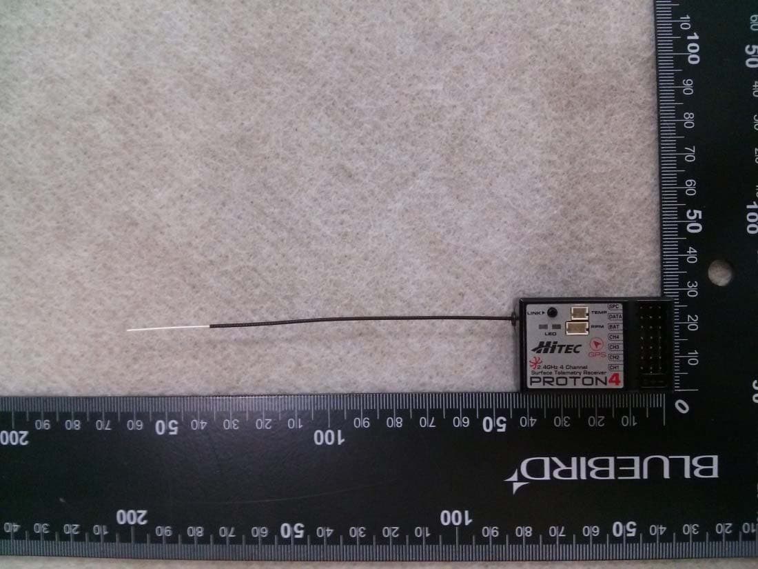
IFHPROTON4
Jul 22, 20142.4GHz Radio Control System
Equipment Class
DSS - Part 15 Spread Spectrum Transmitter
IFHAURORA9X
Aug 19, 20132.4GHz RADIO CONTROL SYSTEM
Equipment Class
DSS - Part 15 Spread Spectrum Transmitter