IFHFOC3F72R/C Transmitter
Hitec RCD Inc.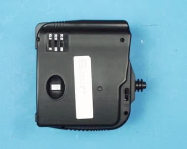
Click to zoom
Application Details
- Equipment Class
- TNB - Licensed Non-Broadcast Station Transmitter
- Date of Grant
- Mar 08, 2000
- Application Purpose
- Original Equipment
- Date of Application
- Jan 20, 2000
- Equipment Note
- R/C Transmitter
- Frequency Range
- 72.01000000 - 72.09000000
- Company
- Hitec RCD Inc.
- Country
- United States
Documents & Files
Document Text
Text extracted from the exhibit documents filed with the FCC. Open a document above to read the original.
Users Manual
Table of Contents 1. Introduction 11. Features and Specifications 111. System Layout IV. Setting and Operation 1. Transmitter a. Loading Batteries b. Reading the LED Battery Indicators c. Recharging NiCad Batteries d. Transmitter Antenna e. Changing Crystals 2. Installation of Receiver and Servos 3. Transmitter, Receiver and Servo Settings a. Checking Operation of the Servo b. Elevator and Rudder Servo Trim Settings - Trim Setting before Flight - Trim Setting during Flight I. Introduction The Focus 3 Single Stick FM radio is specifically made for simple 3 channel Electric, 112A and Sailplane applications. It was ergonomically designed to allow the user to hold onto the transmitter with one hand, while launching the aircraft with the other. The Focus 3 SS FM will prepare you to use radios with more advanced features as your skill level and desire for greater challenges evolve. II. Features and Specifications,, 1. Transmitter - Single stick 3 channel FM proportional system - Dual axis precision gimbal - 3 LED battery status indicators - Charging jack for optional NiCads - Servo reversing for channels I and 2 - Current drain: 180mA - V-tail or Elevon mixing function - Proportional 3rd channel slide switch 2. Receiver - Standard version(HFS-04MI+) Narrow Band 5 channel (with optional "Y" harness) FM receiver - Feather version(Feather receiver) Narrow Band 4 channel (with optional "Y" harness) FM receiver 3. Servo - High impact resin gear - High reliability SMT circuit Ill. System Layout 1. Transmitter a. Loading Batteries You may use either Alkaline "AN' size batteries or optional NiCad batteries. (NiCads recommended) - Push the bottom battery cover in the direction of the arrow then lift up the cover - Load 8 AA batteries (Be sure the polarity is correct) - Reinstall battery case with installed AA batteries with connections to the top left - NiCads should be charged before use b. Reading the LED Battery Indicators Full Power: GreenNormal: Amber Warning: Flashing Red With new alkaline or freshly charged NiCads, the Green light should be lit. With use, the Green light will turn to Amber. If the Red begins to flash, operation should be stopped and the batteries should be recharged or replaced immediately. c. Recharging NiCad Batteries The Focus 3 SS FM is equipped with an external charging jack so there is no need to remove the battery pack from the transmitter. The Hitec CG-22A or 25A are made to charge these type of batteries overnight or for approximately 12-15 hours. Please refer to the following diagram; check to see that the charge lights are lit after the connection is complete. It is advisable to cycle your NiCad batteries at least once every 5 or 6 charges. This can be done by simply turning your transmitter on with the antenna connected and extended to let it run completely dead (Warning!!! Always extend your antenna so as not to overload the circuitry when radio is on.), then follow the charging method and repeat this 3 times, this will remove the memory that the d. Transmitter Antenna Always make sure your antenna is attached and fully extended before use otherwise your operating range will be greatly reduced and could result in damage to your aircraft and or injuries to yourself and others. e. Changing Crystals Changing crystal to avoid conflicts with other aircraft is possible where permitted. (You must check your local rules before doing so. For example in the US the FCC prohibits the changing of transmitter crystals on 72 and 27MHz). If you are allowed to change crystals, both the transmitter and receiver crystals must be changed together. You must hithi thb d i72MH t 72MH 27MH t 27MH difft 2. Installation of Receiver and Servos After connecting the receiver and servos as below illustration, turn on the power to the transmitter first then turn the receiver on. (Always turn the transmitter ON first and OFF last.) This will prevent the receiver from picking up stray signals and ~ going out of control. Now, move the controls to see if the servos are moving properly. 3.Transmitter Receiver and Servo Settings Now we come to the critical part as proper installation of these components are essential. a. Checking Operation of the Servo After installation of the servo and receiver into your model is complete, turn the power "ON" the transmitter (fully extend the antenna) now turn on the receiver. (Note: Do not connect the linkage to the servos until the servo test procedure is completed as unexpected movement may damage the servos or the model) - Check to see if all servos are working properly. If not, check the connections and/or make sure the main battery pack is charged. - If the servos check out fine, connect the linkage to the servo horns now. Check to see that the servos are moving in the correct direction. If not, change the servo direction, with the reversing switches located on the back of the radio. The 3 rd channel of the Focus 3 SS FM is not reversible. - If everything checks out then turn the receiver "OFF" first, then the transmitter. The Focus 3 SS FM offers an internal electronic mix for channels I and 2 to deliver an Elevon or V-tail mix for those aircraft requiring those specific functions. (Always remembers to never have the receiver "ON" without the transmitter being "ON". This means when turning your model "ON" always turn the transmitter "ON" first and "OFF" last) (Note: Please make sure to fold the transmitter antenna after use so as not to get damaged or poke someone in the eyes) Warning!!! : Do not shorten the length of the receiver antenna by cutting off any excess wire. This will severely affect the operating range and could result in injury to yourself and others.. b. Elevator and Rudder Servo Trim Settings -Trim Setting before Flight The servo trim enables minor adjustment of the servo neutral position so that the plane will fly straight when the stick is in the center position. Before adjusting the servo trim, please make sure that when both the stick and t…
Text truncated - open the document above for the full version.
External Photos
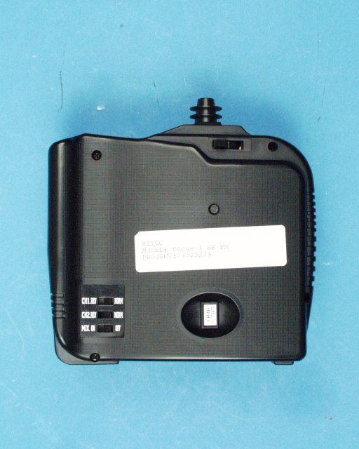
Front View Left Side View Right Side View Back View Top View Bottom View Bottom View w/Battery Compartment
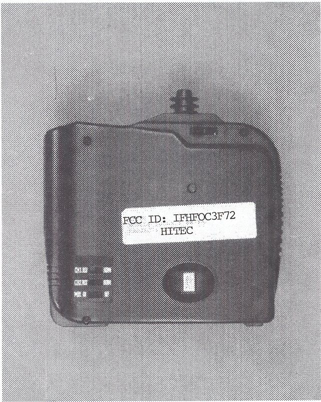
ID Label/Location Info
Equipment Identification Label FCC ID: IFHFOC3F72 FOCUS 3 SS FM TRANSMITTER Hitec MADE IN KOREA
Internal Photos
Interior rear case Component side Track side Interior Front Case
Operational Description
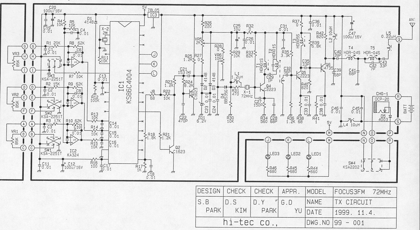
TRANSMITTER TUNE-UP PROCEDURE 1. Attach 12.0 Vdc power supply. 2. Using a spectrum analyzer and a short pick-up antenna, look for 72 MHz signal with sufficient scan width to see 30-150 MHz spurious. 3. Adjust T1, T2, T3 and T4 for maximum output at operating frequency and Minimum output at any harmonics. 4. Repeat Step 3. 5. Check for minimum emissions from 30 to 760.
Test Report
ENGINEERING STATEMENT For Type Certification of Hitec RCD, Inc. Model: Focus 3SS FM FCC ID: IFHFOC3F72 I am an Electronics Engineer, a principal the firm of Hyak Laboratories, Inc., Springfield, Virginia. My education and experience are a matter of record with the Federal Communications Commission. Hyak Laboratories, Inc. has been authorized by Hitec RCD, Inc., to make type certification measurements on the Focus 3SS FM transmitter. These tests were made by me or under my supervision in our Springfield laboratory. Test data and other documentation required by the FCC for type certification are included in this report. It is submitted that the above mentioned transmitter meets FCC requirements and type certification is requested. ______________________________ Rowland S. Johnson Dated: January 4, 2000 A. INTRODUCTION The following data are submitted in connection with this request for type certification of the Focus 3SS FM transmitter in accordance with Part 2, Subpart J of the FCC Rules. The Focus 3SS FM is a low power, non-voice, transmitter in- tended for remote control of model aircraft in the 72 MHz band. The equipment employs a vertical polarized antenna directly mounted on the unit and meets Paragraphs 95.645, 95.647, 95.649, and the technical requirements established in the Report & Order in PR Docket 90-222. B. GENERAL INFORMATION REQUIRED FOR TYPE CERTIFICATION (Paragraph 2.983 of the Rules) 1. Name of applicant: Hitec RCD, Inc. 2. Identification of equipment: IFHFOC3F72 a. The equipment identification label is submitted as a separate exhibit. b. Photographs of the equipment are submitted as separate exhibits. 3. Quantity production is planned. 4. Technical description: a. 6k00A1D emission b. Frequency range: 72.010 – 72.090 MHz. c. Operating power of transmitter is fixed at the factory at 0.443 Watt. d. Maximum power permitted under Paragraph 95.635(b) of the FCC Rules is 750 milliwatts, and the Focus 3SS FM fully complied with those power limi- tations. e. The dc voltage and dc currents at final amplifier: Collector voltage: 11.6 Vdc Collector current: 101 mA f. Function of each active semiconductor device: See Appendix 1. g. Complete schematic diagram is submitted as a separate exhibit. h. Draft instruction book is submitted as a separate exhibit. 2 B. GENERAL INFORMATION (continued) i. The transmitter tune-up procedure is submitted as a separate exhibit. j. A description of circuits for stabilizing frequency is included in Appendix 2. k. A description of circuits and devices employed for suppression of spurious radiation and for limiting modulation is included in Appendix 3. l. Not applicable. 5. Data for 2.985 through 2.997 follow this section. 6. RF_Power_Output (Paragraph 2.985(a) of the Rules) Since the Focus 3SS FM has an immediately attached, integral antenna, no antenna port exists. Power was determined by calcu- lation: P=(E+D) 2 (1) 30 G Where P = Power input (same as power radiated assuming 100% efficient antenna) E = Electric Field in V/M D = Distance in meters G = Gain of the antenna over isotropic. (For a 72 MHz monopole, gain = 0.8) P = (1.086551 x 3) 2 (from Table 1) 30 x 0.8 P = 0.443 watts (1) Kraus, J.D., Antennas p.55. 3 C. MODULATION CHARACTERISTICS Occupied_Bandwidth (Paragraphs 2.989(i), and 95.635(b) of the Rules) Figure 1 is a plot of the sideband envelope of the transmitter taken with an Tektronix 494P spectrum analyzer. Modulation corresponded to conditions of 2.989(i) and consisted of the multiple pulses and synchronizing space normally used in radio control applications. Operator controls were adjusted for worst-case emission. The plot is within the limits imposed by paragraph 95.635(c). The horizontal scale (frequency) is10kHz per division and the vertical scale (Amplitude) is a logarithmic presentation equal to 10 dB per division. Resolution bandwidth was 300 Hz; video bandwidth was 1 kHz. Figure 2 is a plot from a Tektronix 494P spectrum analyzer with 60 mS/division sweep in the time domain of the modulated carrier. Modulation consisted of five bursts with a nominal 2 mS duration at a nominal 50 Hz repetition rate. 4 FIGURE 1 OCCUPIED BANDWIDTH 95.635: (3) At least 25 dB on any frequency removed from the center of the authorized bandwidth by more than 50% up to and including 100% of the authorized bandwidth (4 to 8 kHz). (10) At least 45 dB on any frequency removed from the center of the authorized bandwidth by more than 100% up to and including 125% of the authorized bandwidth. (8 to 10 kHz) (11) At least 55 dB on any frequency removed from the center of the authorized bandwidth by more than 125% up to and including 250% of the authorized bandwidth. (10 to 20 kHz) (12) At least 56+10 log 10 (TP) dB on any frequency removed from the center of the authorized bandwidth by more than 250%. OCCUPIED BANDWIDTH FCC ID: IFHFOC3F72 FIGURE 1 5 FIGURE 2 MODULATING WAVEFORM TIME DOMAIN 60 millisecond/division sweep OCCUPIED BANDWIDTH (Modulating Waveform) FCC ID: IFHFOC3F72 FIGURE 2 6 D. SPURIOUS EMISSIONS AT THE ANTENNA TERMINALS (Paragraph 2.991 of the Rules) Since the Focus 3SS FM transmitter meets FCC Rules 95.645, there are no provisions for antenna terminal output measurements. Substitution of a suitable matching network and retuning to permit observations at 50 ohms would not be representative of normal operation. Accordingly data on radiated spurious emissions are included in lieu of antenna terminal conducted spurious emissions. E. FIELD STRENGTH MEASUREMENTS OF SPURIOUS RADIATION (Paragraph 2.993(a) (b) (2) of the Rules) Field intensity measurements of radiated spurious emissions from the Focus 3SS FM were made with a Tektronix 494P spectrum analyzer using EMCO 3121C calibrated test antennas. The transmitter and its integral vertical antenna were located in an open field 3 meters from the test antenna. Supply voltage was from a fresh set of batteries with a terminal voltage under load of 12.0 Vdc. The transmitter and test antennas were arranged t…
Text truncated - open the document above for the full version.
Contact Information
Applicant
Tony Ohm(Service Dept. Manager)
Technical Contact
Hyak Laboratories, Inc.Rowland S Johnson
[email protected](703) 451-1188
7011 Calamo St., Suite 107 · Springfield, Virginia · United States
Non-Technical Contact
Hyak Laboratories, Inc.Georgia Hall
[email protected](703) 451-1188
Test Firm
Hyak Laboratories, Inc.Rowland Johnson
703-451-1188
Technical Specifications
| # | Rule Parts | Frequency Range | Power Output | Emission | Tolerance |
|---|---|---|---|---|---|
| 1 | 95C | 72.01 MHz - 72.09 MHz | 216.00 mW | 6k00A1D | 0.0020000000 % |
Other Applications from Hitec RCD Inc.
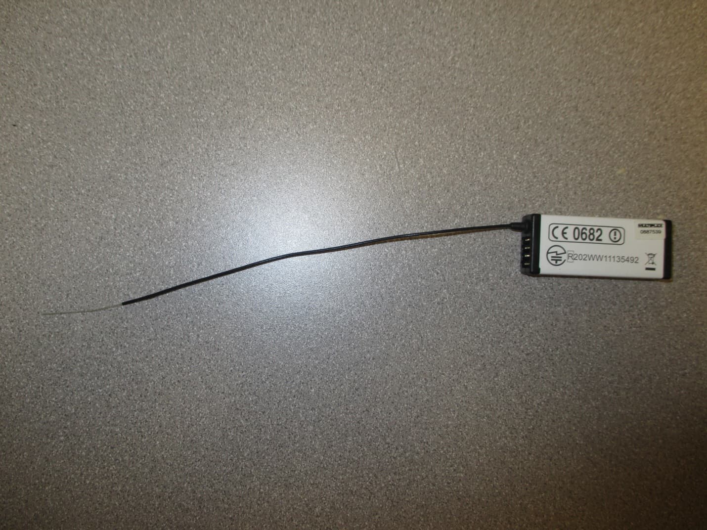
IFHRX57MLINK
Dec 22, 20147 CHANNEL 2.4 GHz TRANSCEIVER
Equipment Class
DSS - Part 15 Spread Spectrum Transmitter
IFHRX5MLINK
Dec 16, 2014RX5 M-LINK CHANNEL 2.4 GHz TRANSCEIVER
Equipment Class
DXX - Part 15 Low Power Communication Device Transmitter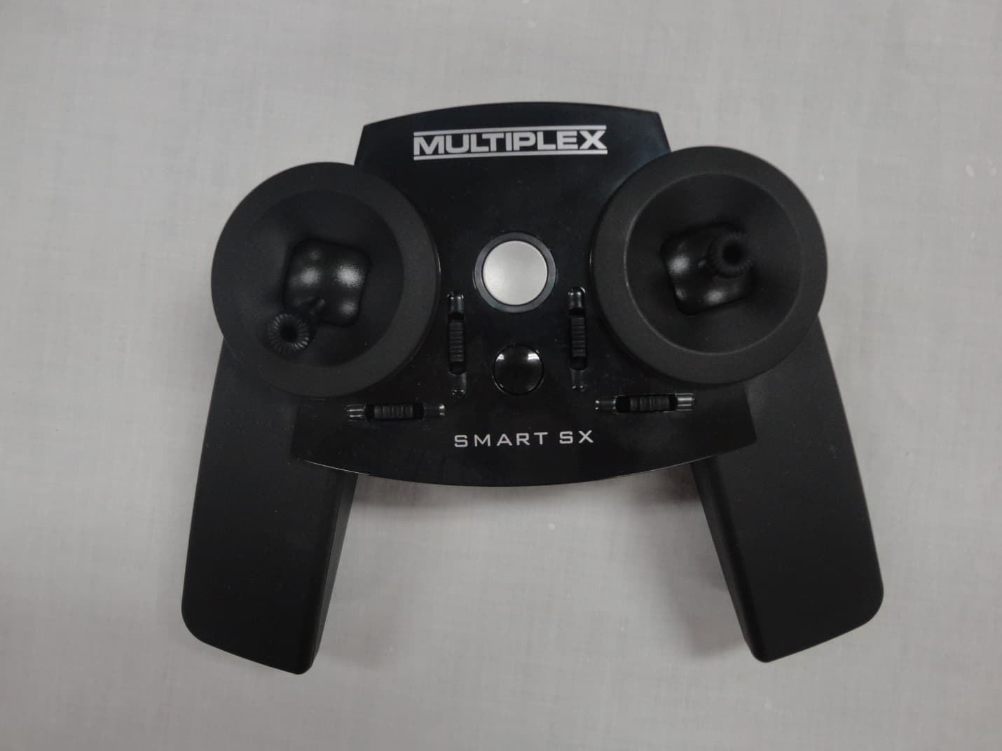
IFHSMART-SX
Sep 16, 20146 CHANNEL 2.4 GHz RADIO CONTROL TRANSMITTER
Equipment Class
DSS - Part 15 Spread Spectrum Transmitter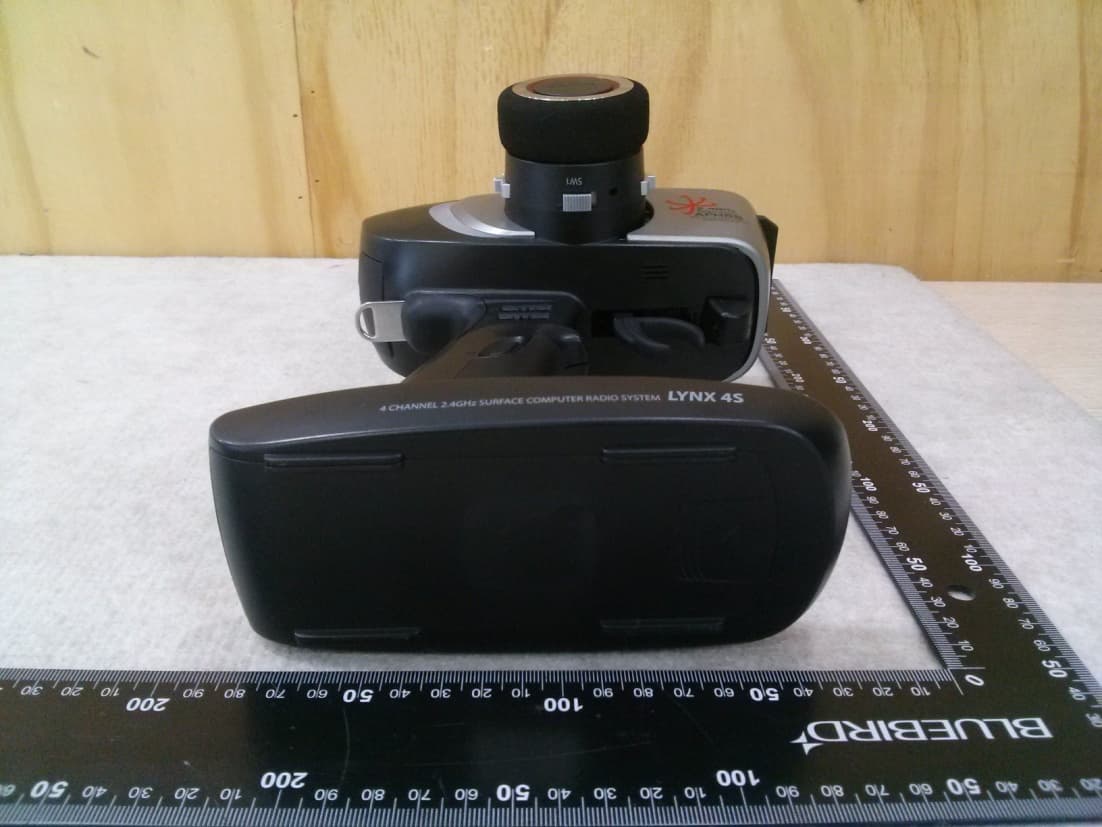
IFHLYNX4S
Jul 22, 20142.4GHz Radio Control System
Equipment Class
DSS - Part 15 Spread Spectrum Transmitter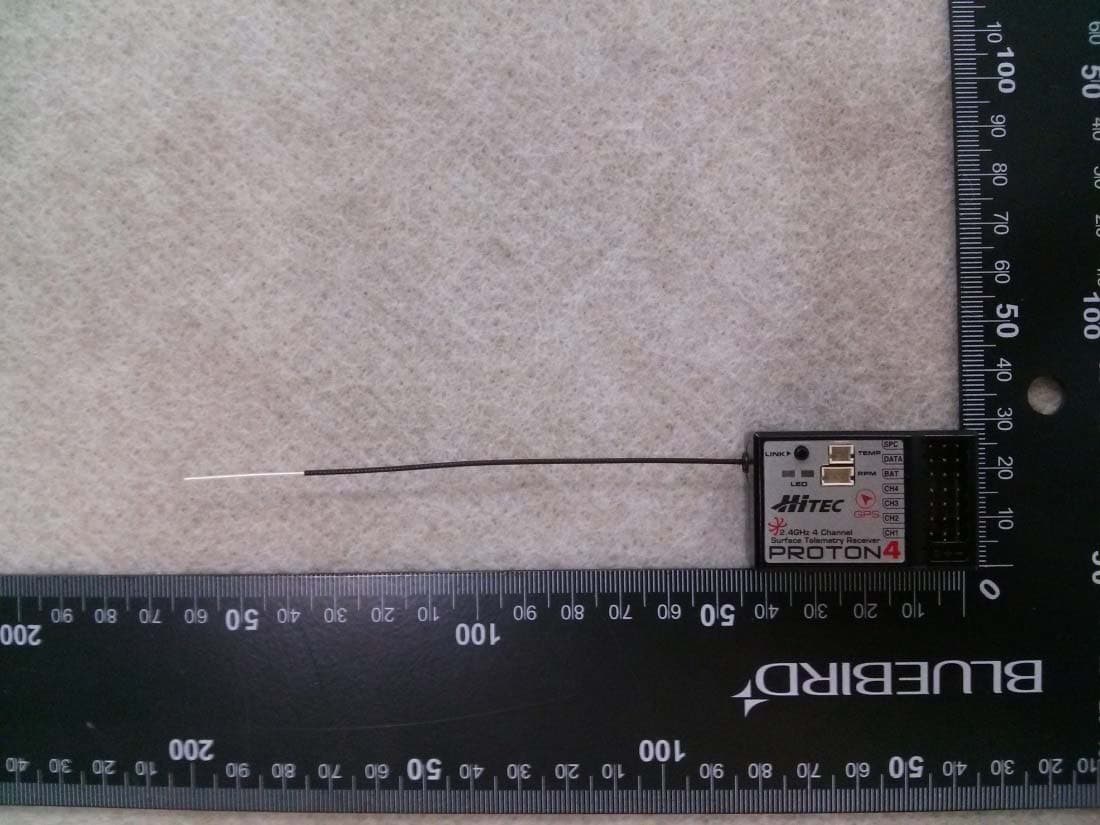
IFHPROTON4
Jul 22, 20142.4GHz Radio Control System
Equipment Class
DSS - Part 15 Spread Spectrum Transmitter