IFHHFMS-7272-73 MHz REMOTE CONTROL TRANSMITTER
Hitec RCD Inc.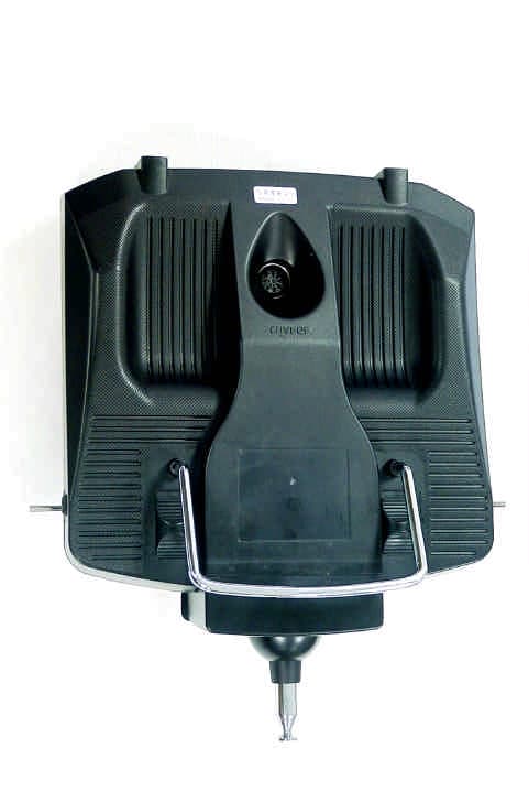
Click to zoom
Application Details
- Equipment Class
- TNB - Licensed Non-Broadcast Station Transmitter
- Date of Grant
- Jul 28, 2003
- Application Purpose
- Original Equipment
- Date of Application
- Jul 28, 2003
- Equipment Note
- 72-73 MHz REMOTE CONTROL TRANSMITTER
- Frequency Range
- 72.00000000 - 73.00000000
- Company
- Hitec RCD Inc.
- Country
- United States
Documents & Files
Document Text
Text extracted from the exhibit documents filed with the FCC. Open a document above to read the original.
Users Manual
M U L T I P L E X M o d e l l t e c h n i k G m b H l N e u e r W e g 1 5 l D - 7 5 2 2 3 N i e f e r n l G e r m a n y © M U L T I P L E X 2 0 0 2 , P r i n t e d i n G e r m a n y Instructions Instructions Page 57 1. Contents 1. Contents 57 2. Introduction 59 3. Safety notes 59 3.1. General safety notes 60 3.2. Range checking 61 4. Liability / Compensation 62 5. Guarantee 62 6. Specification 62 7. The transmitter 63 7.1. Front face of transmitter 63 7.2. Rear face of transmitter 63 7.3. Inside the transmitter 64 7.4. Mechanical details 64 7.4.1. Opening and closing the transmitter case 64 7.4.2. Adjusting the transmitter aerial, fitting a new aerial 65 7.4.3. Installing and removing the RF module 65 7.4.4. Changing the transmitter crystal (HFM-4 module only) 66 7.4.5. Changing the transmitter battery 66 7.4.6. Disabling the stick neutralisation system, installing the spring for ratchet or friction operation 66 7.4.7. Adjust the neutralising force 66 7.4.8. Swivelling the stick units 67 7.4.9. Adjusting and replacing the stick tops 67 7.4.10. Stick top with buttons - how to fit them, how they work 67 7.4.11. Installing the optional switches “P” and “K” 68 8. The transmitter battery 68 8.1. Battery management in the ROYALevo 68 8.1.1. This is what we have already 68 8.1.2. This is NEW 69 8.1.3. This is what you must attend 69 8.2. The essentials in brief 69 8.3. Safety notes 69 8.4. Charging the transmitter battery 70 8.5. Maintaining and storing the transmitter battery 70 8.6. Recycling 70 9. Using the transmitter 71 9.1. Switching on for the first time 71 9.2. The power-ON procedure 71 9.2.1. Switching ON with the HFM-4 RF module for crystals 71 9.2.2. Switching ON with the HFM-S synthesizer RF module 71 9.2.3. Switching ON without transmitting an RF signal 71 9.3. Security queries when switching ON 72 9.3.1. Throttle check 72 9.3.2. RF Check with the synthesizer module 72 9.4. Selecting the channel with an HFM-S synthesizer RF module 72 9.5. The RF status display (red LED) 72 9.6. The status displays 73 10. The basic operating philosophy 74 10.1. The keypad 74 10.1.1. Direct menu access buttons (row 1) 74 10.1.2. Task buttons (row 2) 74 10.1.3. Text input 74 10.2. The 3-D digi-adjustors 75 10.2.1. Programming using the 3-D digi-adjustors 75 10.2.2. Making adjustments using the 3-D digi-adjustors 75 10.3. Working with the keypad and 3-D digi- adjustor -the fundamental operating philosophy 75 10.3.1. Calling up main menus 75 10.3.2. Opening sub-menus 76 10.3.3. Changing values 76 10.3.4. Returning from whence you came 77 11. Digital trims 77 11.1. Introduction 77 11.2. Advantages of digital trims 77 11.3. The cruciform digital trim assembly 78 11.4. On-screen trim display 78 12. Creating a new model 78 12.1. Basic information 78 12.2. A new fixed-wing model 78 12.3. A new helicopter 79 12.4. Model templates in detail 83 12.5. Template: BASIC 83 12.5.1. Assigned transmitter controls and switches 83 12.5.2. Assigned servos / receiver outputs 83 12.5.3. Fine-tuning 83 12.6. Template: ACRO 84 12.6.1. Assigned transmitter controls and switches 84 12.6.2. Assigned servos / receiver outputs 84 12.6.3. Fine-tuning 84 12.7. Template: HOTLINER 84 12.7.1. Assigned transmitter controls and switches 84 12.7.2. Assigned servos / receiver outputs 84 12.7.3. Fine-tuning 84 12.8. Template: DELTA 85 12.8.1. Assigned transmitter controls and switches 85 12.8.2. Assigned servos / receiver outputs 85 12.8.3. Fine-tuning 85 12.9. Template: GLIDER 85 12.9.1. Assigned transmitter controls and switches 85 12.9.2. Assigned servos / receiver outputs 85 12.9.3. Fine-tuning 85 12.10. Template: 4-Flaps 86 12.10.1. Assigned transmitter controls and switches 86 12.10.2. Assigned servos / receiver outputs 86 12.10.3. Fine-tuning 86 12.11. Template: HELImech 86 12.11.1. Assigned transmitter controls and switches 86 12.11.2. Assigned servos / receiver outputs 86 12.11.3. Fine-tuning 86 12.12. Template: HELIccpm 87 12.12.1. Assigned transmitter controls and switches 87 12.12.2. Assigned servos / receiver outputs 87 12.12.3. Fine-tuning 87 13. Main menu „Setup“ LL 87 13.1. Sub-menu „Transmitter“ 87 13.1.1. Parameter „Trim graphics“ 87 13.1.2. Parameter „Sounds“ 87 13.1.3. Parameter „Battery alarm“ 87 13.1.4. Parameter „Battery charge“ 88 13.1.5. Parameter „Contrast“ 88 13.1.6. Parameter „ Check throttle “ 88 13.1.7. Parameter “Check RF” 88 ROYAL evo Page 58 13.2. Sub-menu “Define mixer” 88 13.2.1. How the freely definable mixers work 88 13.2.2. Defining mixers 89 13.2.3. The mixer options 89 13.3. Sub-menu “Assignment” 90 13.3.1. Parameter „Mode“ 91 13.3.2. Parameter „Assignment“ 91 13.3.3. Parameter „Assignment - Name“ 91 13.3.4. Parameter „Assignment - Controls“ 91 13.3.5. Parameter „Assignment - Switches“ 92 13.4. Sub-menu “Training” 92 13.4.1. Teacher/pupil operation 92 13.4.2. The ROYALevo as Teacher transmitter 92 13.4.3. The ROYALevo as pupils transmitter 93 13.5. Sub-menu “User” 93 13.5.1. Parameter „PIN“ 93 13.5.2. Parameter „Language“ 93 13.5.3. Parameter „Name“ 93 14. Main menu „Controls“ HH 93 14.1. Sub-menu „Control switch“ 93 14.2. Sub-menus for individual controls 94 14.2.1. Control settings for the primary axes 94 14.2.2. Parameter „Trim“ 95 14.2.3. Parameter „Step“ (trim increment) 95 14.2.4. Parameter „D/R“ (Dual-Rates) 95 14.2.5. Parameter „Trvl“ 95 14.2.6. Parameter „Expo“ 95 14.2.7. Parameter „Fixed value“ 95 14.2.8. Parameter „Run time“ (Slow) 95 14.2.9. Parameter „Idle“ (idle trim) 95 14.2.10. Parameter „Collective pitch“ (Coll. pitch curve) 95 14.2.11. Parameter "Throttle" (Throttle curve) 96 14.2.12. Parameter „RPM“ speed regulators 96 15. Main menu „Mixers“ GG 97 15.1. Sub-menu „Combi-Switch“ 97 15.2. Sub-menu „A-Diff“ (aileron differential) 97 15.2.1. Parameter „Mode“ 97 15.2.2. Parameter „Diff.“ 97 15.3. Submenu „Gyro“ 97 15.3.1. Parameter „Mode“ 98 15.3.2. Parameter „Heading / Damping“ (Gyro gain) 99 15.3.3. Parameter „Suppression“ 99 15.4. Sub-menu „Tail rotor“ (static tail rotor compensation/…
Text truncated - open the document above for the full version.
Cover Letter(s)
Federal Communications Commission Authorization and Evaluation Division Confidentiality Request regarding application for certification of FCC ID:IFHHFMS-72. Pursuant to Sections 0.457 and 0.459 of the Commission’s Rules, we hereby request confidential treatment of information accompanying this application as outlined below: Schematics Description of Operation Parts List The above materials contain trade secrets and proprietary information not customarily released to the public. The public disclosure of these materials may be harmful to the applicant and provide unjustified benefits to its competitors. The applicant understands that pursuant to Section 0.457 of the Rules, disclosure of this application and all accompanying documentation will not be made before the date of the Grant for this application. Sincerely, Tony Ohm HITEC RCD USA, INC 12115 Paine Street, Poway CA 92064 TEL(858)748-6948 FAX(858)748-1767 WWW.HITECRCD.COM
ID Label/Location Info
11 Chapter 3 FCC Sticker Placement Hitec Royal evo HFMS-72 FCC ID: IFHHFMS-72 Made in Germany
Test Report
APPLICANT: HITEC RCD INC. FCC ID: IFHHFMS-72 REPORT #: H\HITEC\826AUT3\826AUT3TestReport.doc TABLE OF CONTENTS LIST TABLE OF CONTENTS LIST APPLICANT: HITEC RCD INC. FCC ID: IFHHFMS-72 TEST REPORT: PAGE 1.............GENERAL INFORMATION & TECHNICAL DESCRIPTION PAGE 2.............TECHNICAL DESCRIPTION CONTINUED RF POWER OUTPUT PAGE 3.............MODULATION CHARACTERISTICS AUDIO FREQUENCY RESPONSE OCCUPIED BANDWIDTH PAGE 4.............OCCUPIED BANDWIDTH PLOT PAGE 5.............FIELD STRENGTH OF SPURIOUS EMISSION PAGE 6.............METHOD OF MEASURING RADIATED SPURIOUS EMISSIONS PAGE 7.............FREQUENCY STABILITY PAGE 8-11..........TEST EQUIPMENT LIST EXHIBIT CONTAINING: EXHIBIT 1..........CONFIDENTIALITY LETTER EXHIBIT 2..........SCHEMATIC EXHIBIT 3..........PARTS LIST EXHIBIT 4..........USERS MANUAL EXHIBIT 5..........FCC ID LABEL SAMPLE & LOCATION EXHIBIT 6..........EXTERNAL PHOTOGRAPHS EXHIBIT 7..........INTERNAL PHOTOGRAPHS EXHIBIT 8..........OPERATIONAL DESCRIPTION EXHIBIT 9..........TEST SET UP PHOTOGRAPH APPLICANT: HITEC RCD INC. FCC ID: IFHHFMS-72 REPORT #: H\HITEC\826AUT3\826AUT3TestReport.doc Page 1 of 11 GENERAL INFORMATION 2.1033(c)(1)(2) HITEC RCD INC. will sell the FCCID: IFHHFMS-72 Radio Control transmitter in quantity, for use PART 95 SUBPART C. HITEC RCD INC. 12115 PAINE STREET POWAY CA 92064 2.1033(c)(3) Instruction manual is included as exhibit #4. 2.1033 (4) Type of Emission: 8K0F1D 95.631(b)(1) Bn = 2M + 2DK M = 4,800 Bits per second D = 1600 Hz (Peak Deviation) K = 1 Bn = 2(4800/2) + 2(1600)(1) = 4.8K + 3.2K = 8.0k ALLOWED AUTHORIZED BANDWIDTH = 8.00 kHz. 95.631(b) Authorized Bandwidth 8 kHz for RC Transmitter 2.1033(c)(5) Frequency Range: 72-73 MHz 95.623(a) (6) Power Range and Controls: There are NO user Power controls. (7) Maximum Output Power Rating: 0.3 W ERP. (8) DC Voltages and Current into Final Amplifier: FINAL AMPLIFIER ONLY Vce = 7.2Volts DC Ice = 0.039A. Pin = 0.5Watts APPLICANT: HITEC RCD INC. FCC ID: IFHHFMS-72 REPORT #: H\HITEC\826AUT3\826AUT3TestReport.doc Page 2 of 11 2.1033(c)(10) Complete Circuit Diagrams: The circuit diagram is included as part of Exhibit # 2. 2.1033(c)(11) The Equipment identification is shown as Exhibit #5. 2.1033(c)(12) Photographs of the equipment are shown as Exhibits No. 6-7. 2.1033(c)(13) Equipment employing Digital modulation. N/A. 2.1033(c)(14) The data required by 2.1046-2.1057 follows; 2.1046 RF power is measured by the ERP METHOD. There is no provisions to limit the power. With a nominal battery voltage of 7.2 VDC, and the transmitter properly adjusted the RF output measures: Po = 0.3 Watts ERP 2.1046 RF power output. APPLICANT: HITEC RCD INC. FCC ID: IFHHFMS-72 REPORT #: H\HITEC\826AUT3\826AUT3TestReport.doc Page 3 of 11 2.1047 Modulation characteristics: AUDIO FREQUENCY RESPONSE The Voice is NOT allowed in this band. 2.1049 Occupied bandwidth: 95.635(b) (1) At least 25dB on any frequency removed from the center of the authorized bandwidth by more than 50% up to and including 100% of the authorized bandwidth. (10) At least 45 dB on any frequency removed from the center of the authorized bandwidth by more than 100% up to and including 125% of the authorized bandwidth. (11) At least 55 dB on any frequency removed from the center of the authorized bandwidth by more than 125% up to and including 250% of the authorized bandwidth. (12) At least 56 + 10 log 10 (T) dB on any frequency removed from the center of the authorized bandwidth by more than 250%. Radiotelephone transmitter with modulation limiter. Test procedure diagram OCCUPIED BANDWIDTH MEASUREMENT Coupler Transmitter 50 ohm under test Resistive Wattmeter Audio Spectrum Oscillator Analyzer APPLICANT: HITEC RCD INC. FCC ID: IFHHFMS-72 REPORT #: H\HITEC\826AUT3\826AUT3TestReport.doc Page 4 of 11 OCCUPIED BANDWIDTH PLOT APPLICANT: HITEC RCD INC. FCC ID: IFHHFMS-72 REPORT #: H\HITEC\826AUT3\826AUT3TestReport.doc Page 5 of 11 2.1051 SPURIOUS EMISSIONS AT ANTENNA TERMINALS. NOT APPLICABLE, NO antenna port. This UUT has a permanently attached antenna. 2.1053 UNWANTED RADIATION: 95.635(1)(3)(7)(10)(11)(12) REQUIREMENTS: At least 56 + 10log(T) on any frequency removed from the center of the authorized bandwidth by more than 250%. 56 + 10log(0.052) = 43.16 dB TEST DATA: Emission Frequency (MHz) Polarity Antenna Corrected EUT Signal Reading (dBm) Coax Loss Sub. Ant. dB Below Carrier (dBc) 72.80 V 17.2 0 0 0.00 145.70 V -48.0 0 0 65.20 218.60 V -48.3 0 0 65.50 291.50 V -53.0 0 0 70.20 364.40 V -38.9 0 0 56.10 437.30 V -44.2 0 0 61.40 510.20 V -49.7 0 0 66.90 583.10 V -51.1 0 0 68.30 656.00 V -53.4 0 0 70.60 728.80 V -46.4 0 0 63.60 METHOD OF MEASUREMENT: The tabulated data shows the results of the radiated field strength of emissions test. The spectrum was scanned from 30 MHz to at least the tenth harmonic of the fundamental. This test was conducted per TIA/EIA STANDARD 603 using the substitution method while comparing the unit operating into its permanently attached antenna at a height of 80cm. Measurements were made at the open field test site of TIMCO ENGINEERING, INC. located at 849 NW State Road, Newberry, FL 32669. APPLICANT: HITEC RCD INC. FCC ID: IFHHFMS-72 REPORT #: H\HITEC\826AUT3\826AUT3TestReport.doc Page 6 of 11 Method of Measuring Radiated Spurious Emissions Per TIA/EIA STANDARD 603 APPLICANT: HITEC RCD INC. FCC ID: IFHHFMS-72 REPORT #: H\HITEC\826AUT3\826AUT3TestReport.doc Page 7 of 11 2.1055(a)(1) Frequency stability: 95.623(b) Temperature and voltage tests were performed to verify that the frequency remains within the .002%, 20 ppm specification limit. The test was conducted as follows: The transmitter was placed in the temperature chamber at 25 degrees C and allowed to stabilize for one hour. The transmitter was keyed ON for one minute during which four frequency readings were recorded at 15 second intervals. The worse case number was taken for temperature plotting. The assigned channel frequency was considered to be the reference frequency was considered to…
Text truncated - open the document above for the full version.
Contact Information
Applicant
Tony Ohm(Service Dept. Manager)
Test Firm
Timco Engineering, Inc.S Sanders
Technical Specifications
| # | Rule Parts | Frequency Range | Power Output | Emission | Tolerance |
|---|---|---|---|---|---|
| 1 | 95C | 72 MHz - 73 MHz | 300.00 mW | 8K0F1D | 0.0020000000 % |
Other Applications from Hitec RCD Inc.
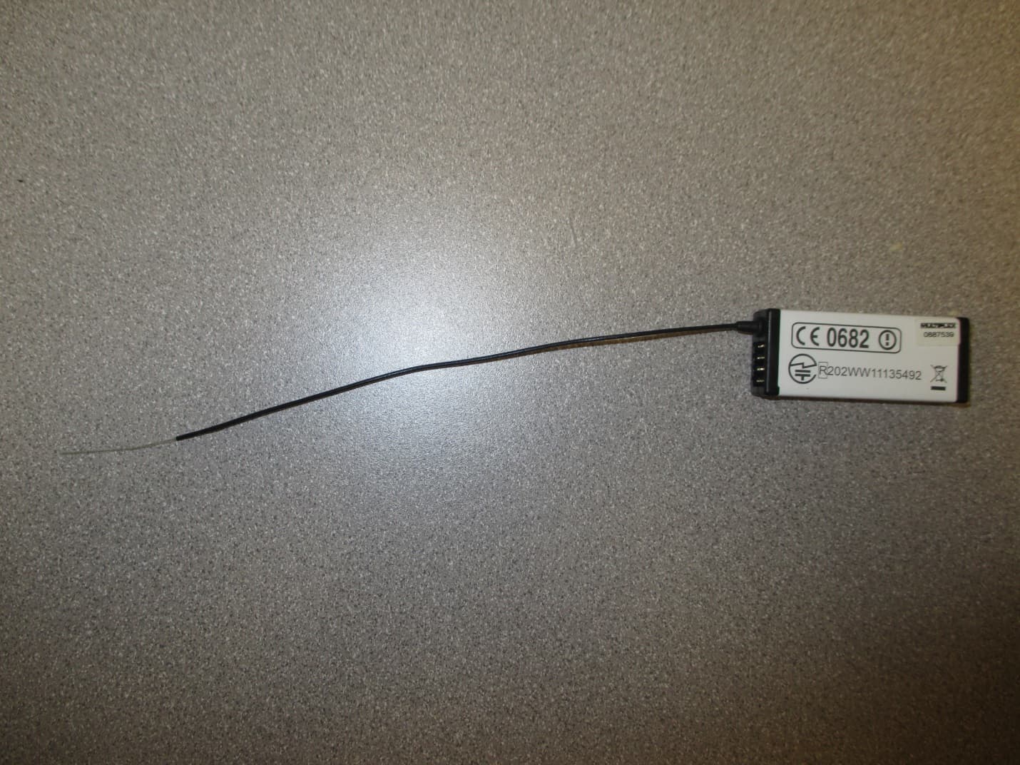
IFHRX57MLINK
Dec 22, 20147 CHANNEL 2.4 GHz TRANSCEIVER
Equipment Class
DSS - Part 15 Spread Spectrum Transmitter
IFHRX5MLINK
Dec 16, 2014RX5 M-LINK CHANNEL 2.4 GHz TRANSCEIVER
Equipment Class
DXX - Part 15 Low Power Communication Device Transmitter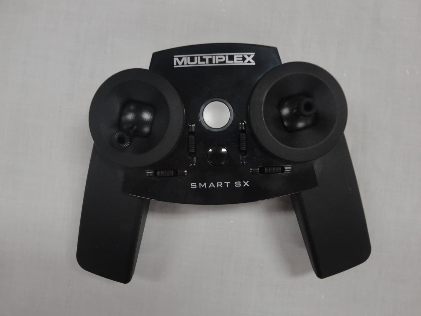
IFHSMART-SX
Sep 16, 20146 CHANNEL 2.4 GHz RADIO CONTROL TRANSMITTER
Equipment Class
DSS - Part 15 Spread Spectrum Transmitter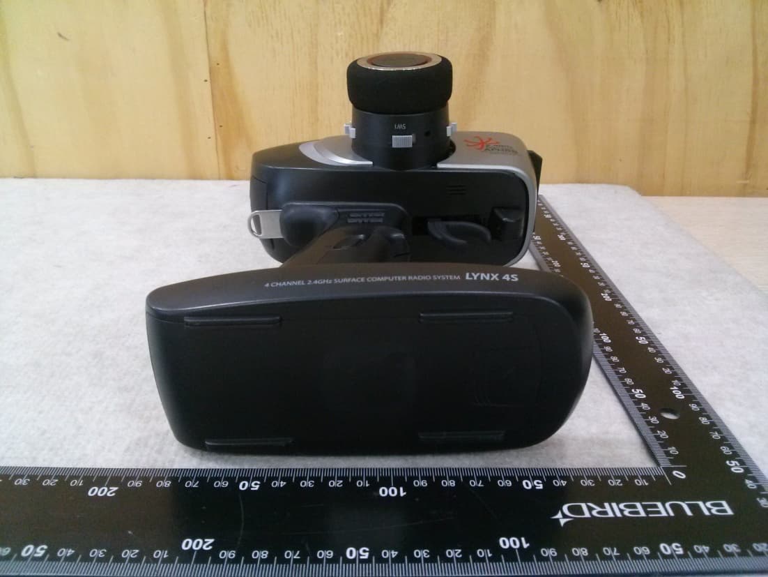
IFHLYNX4S
Jul 22, 20142.4GHz Radio Control System
Equipment Class
DSS - Part 15 Spread Spectrum Transmitter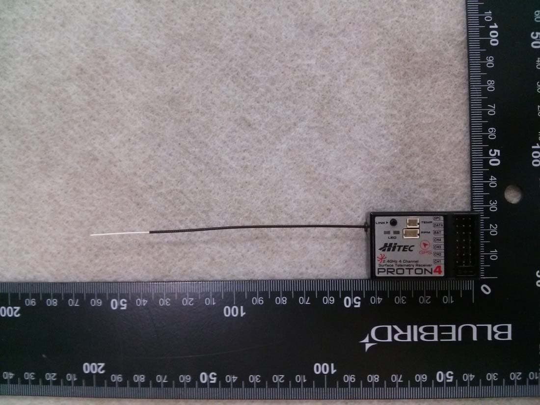
IFHPROTON4
Jul 22, 20142.4GHz Radio Control System
Equipment Class
DSS - Part 15 Spread Spectrum Transmitter