IFHHFMS-CAR-75REMOTE CONTROL - TRANSMITTER
Hitec RCD Inc.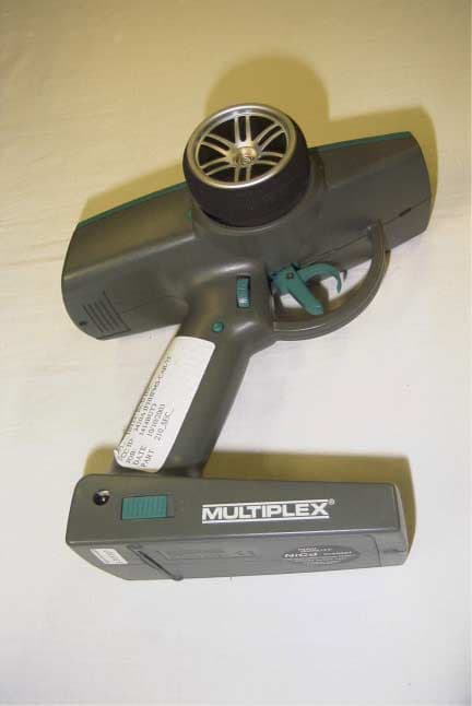
Click to zoom
Application Details
- Equipment Class
- TNB - Licensed Non-Broadcast Station Transmitter
- Date of Grant
- Nov 06, 2003
- Application Purpose
- Original Equipment
- Date of Application
- Nov 06, 2003
- Equipment Note
- REMOTE CONTROL - TRANSMITTER
- Frequency Range
- 75.41000000 - 75.99000000
- Company
- Hitec RCD Inc.
- Country
- United States
Documents & Files
Document Text
Text extracted from the exhibit documents filed with the FCC. Open a document above to read the original.
Users Manual
PROFI CAR 403 and 707 Operating instructions Before operating the transmitter, please select the language (see 9.4, page 42)! 2 Dear customer, dear fellow modeller, we are delighted that you have decided to purchase a MULTIPLEX radio control system. The „PROFI CAR“ is the first „pistol-grip“ transmitter designed and developed by MULTIPLEX. Ergonomic efficiency and user-friendliness were our top priority during the development process. That’s not to say that we have neglected performance: the new system includes many innovative and practical features, offering you facilities which until now have not been available in systems of this class. They include: v Interchangeable RF module, switchable to suit AM and FM receivers v Up to 7 channels (steering, throttle/brake + 5 auxiliary channels) v 2 steering servos and 2 brake servos (PROFI CAR 707 only) v Separate throttle servo (PROFI CAR 707 only) Of course, you don’t need to use these features; you can still operate the PROFI CAR as a „completely normal“ set, i.e. with one steering servo and a second servo for throttle/brake. We are confident that you will have many hours of pleasure with your PROFI CAR. Yours the MULTIPLEX team A quick look at the transmitter Transmitter crystal CAUTION: Use only genuine MULTIPLEX crystals RF module Charge socket maximum 600 mA ON/OFF switch Aerial (screw fitting) Menu buttons Screen Transmitter battery in base With thermal fuse! 3 Contents A quick look at the transmitter 2 Contents 3 Safety 5 System facilities 6 The transmitter controls in detail 7 The „instrument panel“ (screen) 8 The principle 9 Switching on for the first time 11 1.1. Charging the transmitter battery (maximum charge current 1 A) 11 1.2. Charging the receiver battery 11 1.3. Fitting the transmitter crystal 11 1.4. Adjusting the trigger loop 11 1.5. Testing the transmitter 12 2. Short and to the point 12 2.1. Selecting the vehicle TYPE 13 2.2. Setting the servo norm, direction of rotation, travels and centre 14 2.3. Adjusting STEERING L 15 2.4. Adjusting THROTTLE A 15 2.5. Adjusting BRAKE A 16 3. More about steering LL 17 3.1. Adjusting the steering servo („T“ menu) 17 3.2. Adjusting the steering trim („T“ menu) 19 3.3. Adjusting the steering CENTRE, accepting the trim setting 19 3.4. Setting the minimum steering TRAVEL 20 3.5. SLOW 21 3.6. EXPO 21 3.7. Auto Dual Rates for steering 21 3.7.1. Reduced Travel RT at full throttle 22 3.7.2. Auto Dual Rate delay 22 3.8. The second steering servo (PROFI CAR 707 only) 22 4. More about THROTTLE AA 23 4.1. 2-point throttle curve with EXPO 23 4.2. 5-point throttle curve 24 4.3. Automatic Start 25 4.3.1. Setting the „addition“ for Initial Throttle „IT+“ 25 4.3.2. Initiating the automatic start function using the trigger 26 4.3.3. Initiating the start function with the handle button or trigger 26 4.3.4. Terminating the automatic start phase 26 4.4. TC = traction control (nur PROFI CAR 707) 27 5. More about BRAKE 28 5.1. Two-point brake curve with EXPO 28 5.2. Trimming the Lock Point LP using rocker D 29 5.3. ABS = Advanced Braking System (PROFI CAR 707 only) 30 5.4. Braking with more than one servo (PROFI CAR 707 only) 31 4 6. Timers and lap counters ∫∫ 0000 33 6.1. Timer mode 33 6.2. Lap time memory 34 6.3. Setting the nominal time T-NOM 35 6.4. Setting the race duration (timer mode 3 only 35 6.4.1. Race duration by laps 35 6.4.2. Race duration by time 35 6.5. Checking the transmitter’s operating time 36 6.6. Erasing the timer ERASE 36 7. Model memories 11 37 7.1. Switching to a different model memory 37 7.2. Copying 37 7.3. Entering the model name 38 7.4. Erasing 38 7.5. Reverting to the PREVious state 38 8. Driving trucks 39 8.1. Selecting the model type 2+5 CH (truck) 40 8.2. Setting the control mode for the auxiliary channels 40 8.3. Adjusting travel and centre of the auxiliary channels 41 8.4. Truck steering and throttle/brake 41 9. The “toolbox” TT 41 9.1. Adjusting the trigger deadband („T “ menu, DEADB) 41 9.2. Switching between AM and FM („T “ menu, AM-FM) 42 9.3. Entering the owner’s name („T “ menu, NAME) 42 9.4. Selecting the display language („T “ menu, TEXT) 42 9.5. Setting the battery alarm threshold („T “ menu, ALARM) 42 10. Tips on installing the receiving system in the model 43 11. The system in use 44 11.1. Post Office Regulations for the U.K. 44 11.2. Range testing 44 11.3. Care of the transmitter 45 11.4. Maintenance 45 Specification, system characteristics 46 Menu summary for the PROFI CAR 403 and 707 47 5 Safety Radio-controlled models are not toys! You can make a major contribution to safety when operating your models by acting responsibly and handling your radio control system and model with due care. v Check the electrical and mechanical connections in the model at regular intervals. v Check all moving parts regularly: they must be free to move, and must not exhibit undue lost motion. v Carry out regular range checks (see „Range testing“). v When other drivers are present at the track, find out which channels are already in use before you switch on. v Before every run: extend the transmitter aerial to full length, and check that it is in good condition and firmly seated. v Check that you have selected the model memory corresponding to the model you are running. v Check all the working systems in your model before you start: Do the servos rotate in the correct direction? Are the travels correct? v Are the transmitter and receiver battery adequately charged, and in well maintained and roadworthy condition? v Use only genuine MULTIPLEX crystals, batteries and accessories. v If your receiving system includes components which are not covered by these operating instructions, be sure to read the instructions supplied with those items. If you are in doubt on any point - don’t operate your model! Take your time, carefully check the system again, and eliminate the fault. If you cannot solve the problem, your local model shop or the MULTIPLEX customer service department will be pleased t…
Text truncated - open the document above for the full version.
Block Diagram
VC0 IC2IC3 T1IC4 Driver T3 T4 PA T5 Micro-Controller IC1 IC5 Modulation Ser-in Ser-out PLL - Chan-Control VC0 -off Driver-off Ant Functional Block Diagram HFMS-Car-75
Cover Letter(s)
Request for Confidentiality 10/28/2003 Timco Engineering 849 N.W. State Road 45 P.O. BOX 370 Newberry, FL 32669 FCC ID: IFHHFMS-CAR-75 Please be advised that the following information is to be held confidential on behalf of Hitec RCD, Inc: Schematics Part List Description of Operation This application contains technical information that Hitec RCD, Inc. deems to be trade secrets and proprietary. If made public, the information might be used to the disadvantage of the applicant in the market place. Thank you Tony Ohm
ID Label/Location Info
12 Chapter 3 Label Location The identification label will be located on the top of the module. The following will be printed on the label: FCC ID: IFHHFMS-CAR-75 HFMS-CAR-75 HITEC MADE IN GERMANY CANADIAN ID:
Parts List/Tune Up Info
6 Tuning Procedure 1. Attach a 7.2V power supply 2. Using a Spectrum analyzer and a short-range pick-up antenna, look for 75MHz signal with sufficient scan width to see 30-150 MHz spurious. 3. Adjust FI2, FI3, FI4, and FI5 for maximum output at operating frequency and minimum output at any harmonics. 4. Repeat step 6. 5. Check for minimum emissions from 30 to 760 MHz.
Test Report
APPLICANT: HITEC RCD INC. FCC ID: IFHHFMS-CAR-75 REPORT #: H\HITEC\1414UT3\1414UT3TestReport.doc TABLE OF CONTENTS TABLE OF CONTENTS LIST APPLICANT: HITEC RCD INC. FCC ID: IFHHFMS-CAR-75 TEST REPORT: PAGE 1............GENERAL INFORMATION & TECHNICAL DESCRIPTION PAGE 2............TECHNICAL DESCRIPTION CONTINUED RF POWER OUTPUT PAGE 3............MODULATION CHARACTERISTICS OCCUPIED BANDWIDTH PAGE 4............OCCUPIED BANDWIDTH PLOT PAGE 5............FIELD STRENGTH OF SPURIOUS EMISSION PAGE 6............METHOD OF MEASURING RADIATED SPURIOUS EMISSIONS PAGE 7............FREQUENCY STABILITY PAGE 8-11.........TEST EQUIPMENT LIST EXHIBIT CONTAINING: EXHIBIT 1.........CONFIDENTIALITY LETTER EXHIBIT 2.........BLOCK DIAGRAM EXHIBIT 3.........SCHEMATIC EXHIBIT 4.........USERS MANUAL EXHIBIT 5.........PARTS LIST EXHIBIT 6.........LABEL SAMPLE & LOCATION EXHIBIT 7.........EXTERNAL PHOTOGRAPHS EXHIBIT 8.........INTERNAL PHOTOGRAPHS EXHIBIT 9.........TUNING PROCEDURE EXHIBIT 10........CIRCUIT DESCRIPTION EXHIBIT 11........TEST SET UP PHOTOGRAPH APPLICANT: HITEC RCD INC. FCC ID: IFHHFMS-CAR-75 REPORT #: H\HITEC\1414UT3\1414UT3TestReport.doc Page 1 of 11 GENERAL INFORMATION 2.1033(c) (1)(2) HITEC RCD INC. will sell the FCC ID: IFHHFMS-CAR-75 Radio Control transmitter in quantity, for use PART 95 SUBPART C. HITEC RCD INC. 12115 PAINE STREET POWAY, CA 92064 2.1033(c) (3) Instruction manual is included as exhibit #3. 2.1033 (4) Type of Emission: 8K0F1D 95.631 (b) (1) Bn = 2M + 2DK M = 4,800 Bits per second D = 800 Hz (Peak Deviation) K = 1 Bn = 2(4800/2) + 2(800)(1) = 4.8K + 3.2K = 8.0k ALLOWED AUTHORIZED BANDWIDTH = 8.00 kHz. 95.631 (b) Authorized Bandwidth 8 kHz for RC Transmitter 2.1033(c) (5) Frequency Range: 75.41-75.99 MHz 95.623 (a) (6) Power Range and Controls: There are NO user Power controls. (7) Function of each electron tube or semiconductor device or other active circuit device: See Exhibit #5. (8) Maximum Output Power Rating: 0.019 W ERP. (9) DC Voltages and Current into Final Amplifier: FINAL AMPLIFIER ONLY Vce = 7.2 Volts DC Ice = 0.039 A. Pin = 0.5 Watts 2.1033(c) (10) Tune-up procedure. The tune-up procedure is included a Exhibit #9. APPLICANT: HITEC RCD INC. FCC ID: IFHHFMS-CAR-75 REPORT #: H\HITEC\1414UT3\1414UT3TestReport.doc Page 2 of 11 2.1033(c) (10) Complete Circuit Diagrams: The circuit diagram is included as part of Exhibit # 3. (10) Description of all circuitry and devices provided for determining and stabilizing frequency is given in EXHIBIT #10. 2.1033(c) (11) The Equipment identification is shown as Exhibit #6. 2.1033(c) (12) Photographs of the equipment are shown as Exhibits No. 7-8. 2.1033(c) (13) Equipment employing Digital modulation. N/A. 2.1033(c) (14) The data required by 2.1046-2.1057 follows; 2.1046 RF power is measured by the ERP METHOD. There are no provisions to limit the power. With a nominal battery voltage of 7.2 VDC, and the transmitter properly adjusted the RF output measures: Po = 0.019 Watts ERP 2.1046 RF power output. APPLICANT: HITEC RCD INC. FCC ID: IFHHFMS-CAR-75 REPORT #: H\HITEC\1414UT3\1414UT3TestReport.doc Page 3 of 11 2.1047 Modulation characteristics: AUDIO FREQUENCY RESPONSE The Voice is NOT allowed in this band. 2.1049 Occupied bandwidth: 95.635(b) (1) At least 25dB on any frequency removed from the center of the authorized bandwidth by more than 50% up to and including 100% of the authorized bandwidth. (10) At least 45 dB on any frequency removed from the center of the authorized bandwidth by more than 100% up to and including 125% of the authorized bandwidth. (11) At least 55 dB on any frequency removed from the center of the authorized bandwidth by more than 125% up to and including 250% of the authorized bandwidth. (12) At least 56 + 10 log 10 (T) dB on any frequency removed from the center of the authorized bandwidth by more than 250%. Radiotelephone Transmitter with Modulation Limiter Test Procedure Diagram OCCUPIED BANDWIDTH MEASUREMENT TRANSMITTER UNDER TEST AUDIO OSCILLATOR 50 ohm RESISTIVE WATTMETER APPLICANT: HITEC RCD INC. FCC ID: IFHHFMS-CAR-75 REPORT #: H\HITEC\1414UT3\1414UT3TestReport.doc Page 4 of 11 OCCUPIED BANDWIDTH PLOT APPLICANT: HITEC RCD INC. FCC ID: IFHHFMS-CAR-75 REPORT #: H\HITEC\1414UT3\1414UT3TestReport.doc Page 5 of 11 2.1051 SPURIOUS EMISSIONS AT ANTENNA TERMINALS. NOT APPLICABLE, NO antenna port. This UUT has a permanently attached antenna. 2.1053 UNWANTED RADIATION: 95.635(1)(3)(7)(10)(11)(12) REQUIREMENTS: At least 56 + 10log(T) on any frequency removed from the center of the authorized bandwidth by more than 250%. 56 + 10log(0.019) = 38.79 dB TEST DATA: Emission Frequency MHz Ant. Polarity Corrected EUT Signal Reading Coax Loss (dB) Substitution Antenna (dBd) dB Below Carrier (dBc) 75.41V 12.80 0 0 0 150.82V -24.9 0 -1.49 38.95 226.23V -39.60 0 -1.25 53.89 301.64V -48.50 0 -1.21 62.55 377.05V -55.10 0 -1.24 69.11 452.46V -49.90 0 -1.49 63.94 527.87H -59.30 0 -1.45 73.59 603.28H -56.50 0 -1.48 70.75 678.69H -56.30 0 -1.65 70.58 754.10H -48.90 0 -1.44 63.35 METHOD OF MEASUREMENT: The procedure used was C63.4-1992. The unit was operating into its permanently attached antenna at a height of 80 cm. The spectrum was scanned from 30 to at least the tenth harmonic of the fundamental using a HP model 8566B spectrum analyzer and an appropriate antenna. Measurements were made at the open field test site of TIMCO ENGINEERING INC. located at 849 N.W. State Road 45 Newberry, FL 32669. APPLICANT: HITEC RCD INC. FCC ID: IFHHFMS-CAR-75 REPORT #: H\HITEC\1414UT3\1414UT3TestReport.doc Page 6 of 11 Method of Measuring Radiated Spurious Emissions Hewlett Packard Spectrum Analyzer HP8566B Transmitter Under Test Integral Antenna Power Supply Tuned, Calibrated Antenna which may be raised from 1m to 4m above ground and changed in polarization <- 3,0m -> Equipment placed 80cm above ground on a rotatable platform. APPLICANT: HITEC RCD INC. FCC ID: IFHHFMS-CAR-75 REPORT #: H\HITEC\1414UT3\1414UT3TestReport.doc Page 7 of 11 2.1055(a)(1) Freq…
Text truncated - open the document above for the full version.
Contact Information
Applicant
Tony Ohm(Service Dept. Manager)
Test Firm
Timco Engineering, Inc.S Sanders
Technical Specifications
| # | Rule Parts | Frequency Range | Power Output | Emission | Tolerance |
|---|---|---|---|---|---|
| 1 | 95C | 75.41 MHz - 75.99 MHz | 19.00 mW | 8K00F1D | 20.0000000000 ppm |
Other Applications from Hitec RCD Inc.
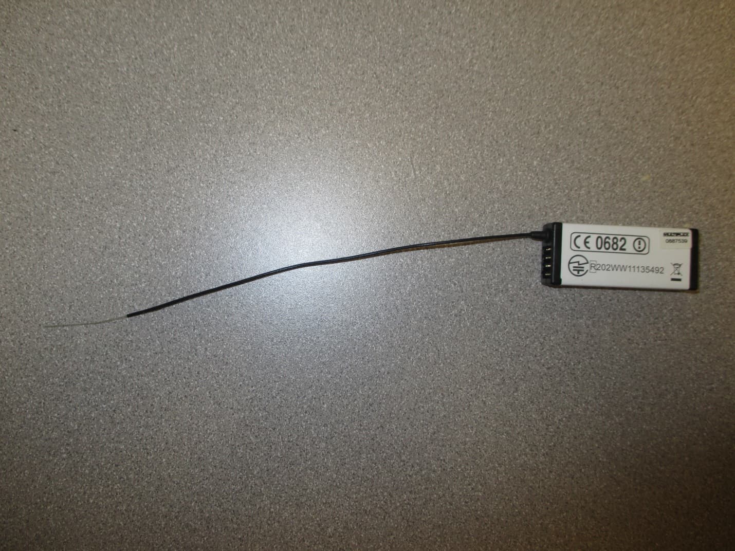
IFHRX57MLINK
Dec 22, 20147 CHANNEL 2.4 GHz TRANSCEIVER
Equipment Class
DSS - Part 15 Spread Spectrum Transmitter
IFHRX5MLINK
Dec 16, 2014RX5 M-LINK CHANNEL 2.4 GHz TRANSCEIVER
Equipment Class
DXX - Part 15 Low Power Communication Device Transmitter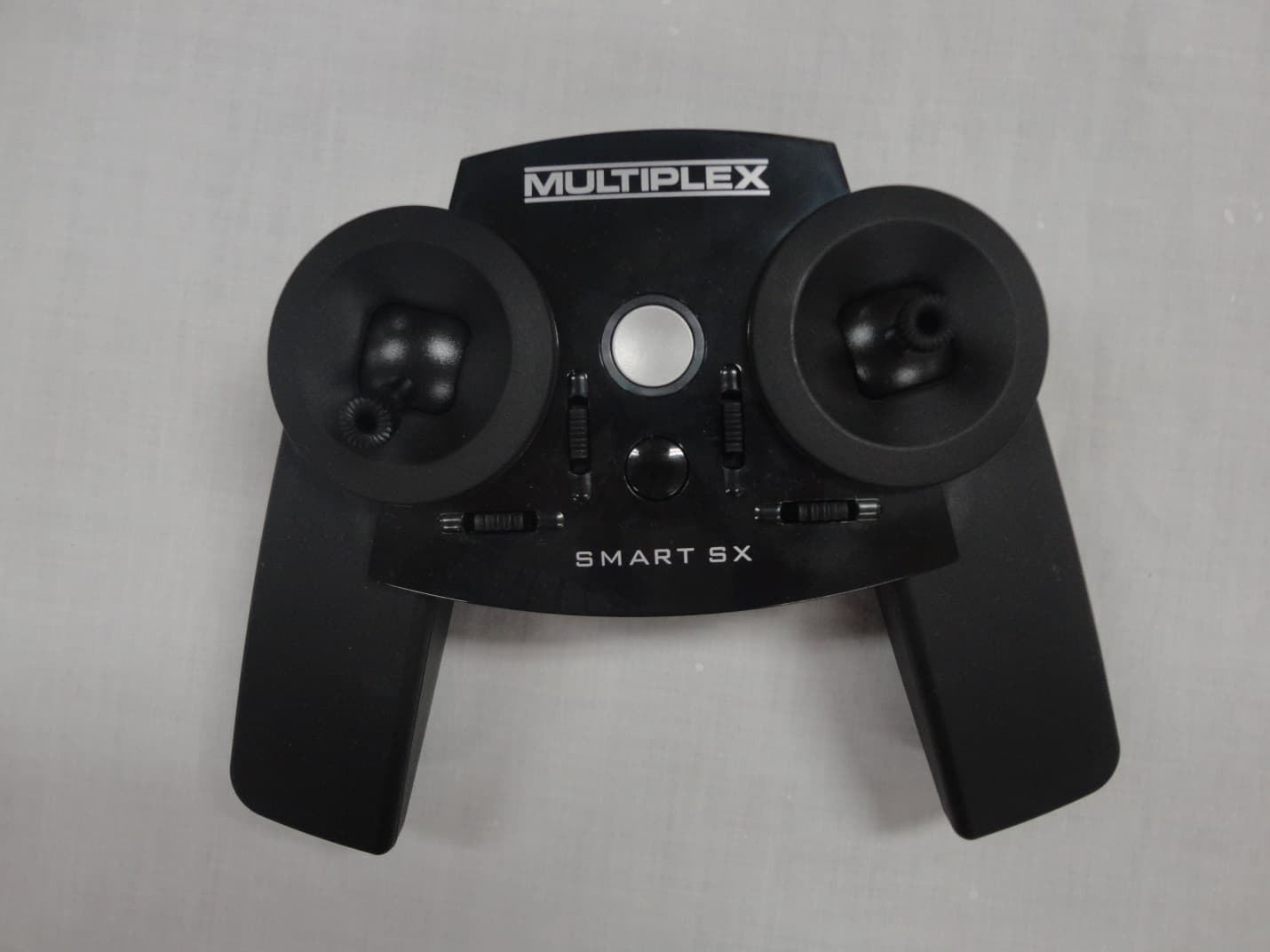
IFHSMART-SX
Sep 16, 20146 CHANNEL 2.4 GHz RADIO CONTROL TRANSMITTER
Equipment Class
DSS - Part 15 Spread Spectrum Transmitter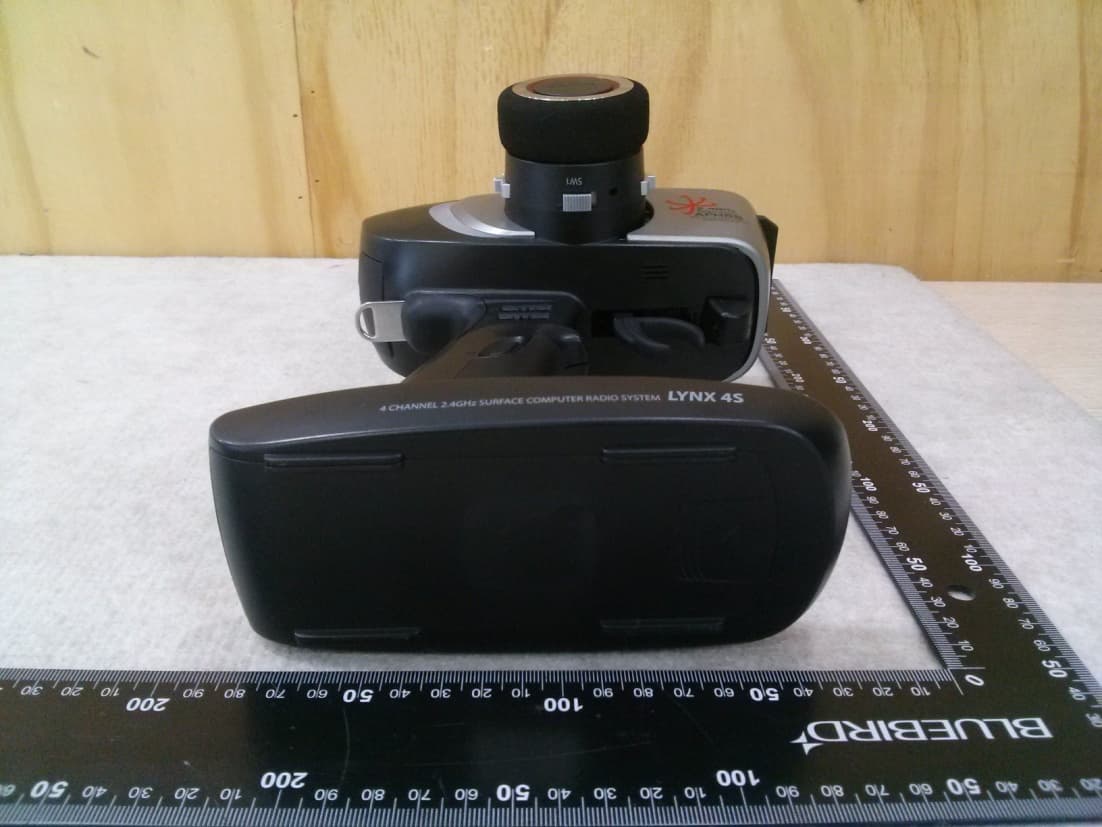
IFHLYNX4S
Jul 22, 20142.4GHz Radio Control System
Equipment Class
DSS - Part 15 Spread Spectrum Transmitter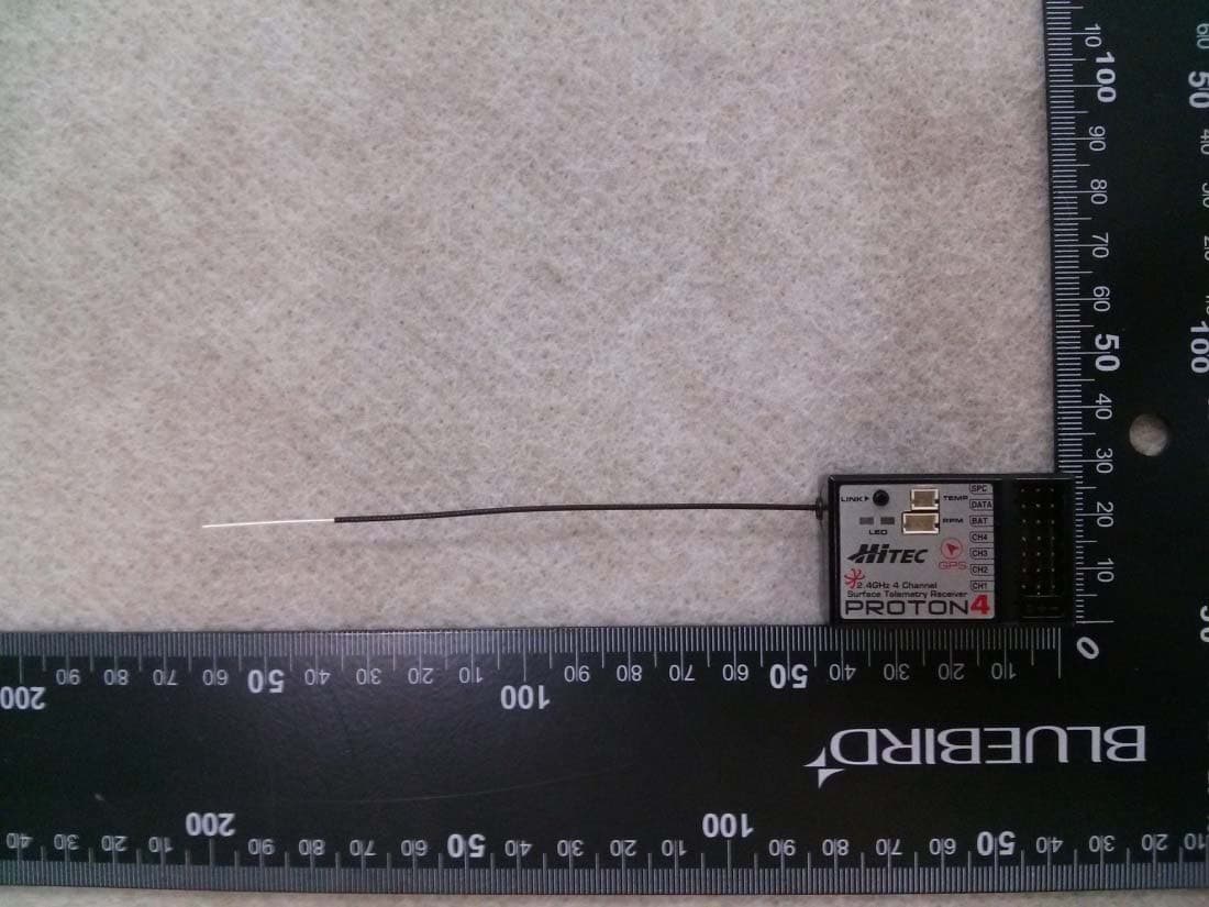
IFHPROTON4
Jul 22, 20142.4GHz Radio Control System
Equipment Class
DSS - Part 15 Spread Spectrum Transmitter