IFHLAS46R/C Transmitter
Hitec RCD Inc.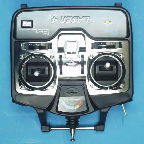
Click to zoom
Application Details
- Equipment Class
- TNB - Licensed Non-Broadcast Station Transmitter
- Date of Grant
- May 10, 2001
- Application Purpose
- Original Equipment
- Date of Application
- May 10, 2001
- Equipment Note
- R/C Transmitter
- Frequency Range
- 72.01000000 - 72.99000000
- Company
- Hitec RCD Inc.
- Country
- United States
Documents & Files
Document Text
Text extracted from the exhibit documents filed with the FCC. Open a document above to read the original.
Users Manual
Introduction Thank you for purchasing the Hitec Laser digital proportional radio control system. The Laser is loaded with easy to use features and built with modern solid-state components for unsurpassed reliability and performance. It is important that you read and understand this manual before you attempt to operate your system. Table of Contents Introduction/ Table of contents................................................Page 1. System Specifications............................................................Page 2. 1. Transmitter a. Features................................................................... b. Layout.................................................................... c. Specifications........................................................... d. Servo Reversing........................................................ e. EPA (End Point Adjustment)........................................ f. Mixing................................................................... g. Control Stick adjustment............................................... h. Gimble tension adjustment............................................. i. Trim levers................................................................ 2. Receiver a. Features..................................................................... b. Layout...................................................................... c. Specifications.............................................................. d. Installation.................................................................. 3. Servo a. Features....................................................................... b. Layout........................................................................ c. Specifications............................................................... d. Installation.................................................................. 4. Charging Specifications a. Transmitter battery............................................................. b. Receiver battery............................................................. 5. Operation a. Trainer system.................................................................. b. Range checking.................................................................. 6. Replacement Parts & Accessories..................................................... System Specifications 1. Transmitter A. Features • Ergonomically designed 4 channel FM transmitter. • High quality precision gimbals with adjustable length and tension. • Servo reversion on all 4 channels. • ATV (Adjustable Travel Volume) CH1, CH2. • V-tail and Elevon mixing. • Trainer system (Hitec/Futaba compatible). • Easy to read LED battery indicators. • Premium 9.6v Nicad rechargeable battery pack • Neck strap attachment. • Carrying handle B. Layout • (Show drawing and point to features ) C. Specifications • Operating system: Two stick • Power supply: 9.6V (8 cell) Nicad battery • Current drain: 150mA • Output power: 500mw • Modulation: PPM (FM) D. Servo Reversing • The Laser 4 FM transmitter is equipped with servo reversing on all 4 channels. • (Show Illustration) • (Note: Leaving the switch in the middle will cause the radio to work erratically so please make sure that the switches are all pushed to the furthest end.) E. A.T.V. (Adjustable Travel Volume) • CH 1 & CH 2 only • This function adjusts the servo overall throw from left to right on CH 1 and up and down on CH 2. • The rate setting is from 30% -110% (Show Illustration) F. Mixing • The Laser 4 is equipped with mixing for V-tail (CH2 & CH4) or Elevon (CH1 & CH2) for use with flying wing or V-tail type aircraft. (Show Illustration) G. Control Stick Adjustment • The length of the non-slip control sticks can be adjusted to suit the requirements of the user. • See Illustration. (Show Illustration) H. Gimble Tension Adjustment • The unique open-stick assembly provides fully adjustable stick tension to adjust the “feel” of the sticks in your hands. • Turning the adjustment counter clockwise will reduce or “soften” the stick tension while turning it clockwise will increase or “stiffen” the tension. • See Illustration. (Show Illustration) I. Trim Levers • The trim levers associated with each control stick are used to correct (trim out) the tracking of the aircraft. • (Caution) Make sure the trims will move the surface past neutral when moved to their extremes. This will assure you have adequate trim control • During the initial test flight, note the positions of the control surfaces that required trim. • Next, center the trims and turn the receiver off. Now adjust the control linkage on the plane so the surfaces are in the same position before the trim levers are re-centered. • Turn on the radio and receiver and recheck the control surfaces to ensure that all the corrections were applied in the proper direction. 2. Receiver A. Features • 8 Channels • Dual conversion • Narrow Band • Crystal Interchangeable B. Layout (Show picture) • Channel #1: Aileron or rudder (If aircraft does not have ailerons) • Channel #2: Elevator • Channel #3: Throttle • Channel #4: rudder (If plane has ailerons) • Channel #5: Gear (Laser 6 only) • Channel #6: Flaps (Laser 6 only) • Channel #7: Not used • Channel #8/Batt: Battery C. Specifications • Power supply: 4.8 – 6 volts • Current drain: 22mA • Dimensions: 2.3”x 1.4”x 0.8” • Weight: 1.34 oz (34 grams) • Range: Line of sight to 3,500 ft. • Operating voltage: 3.7 – 7.0 volts D. Installation • Always wrap receiver in the supplies protective foam padding. • Do not coil the antenna. • When turning on the system always turn the transmitter on first and off last. • See aircraft manufacturers instructions for proper airborne radio system location. 3. Servos A. Features • Indirect drive • Custom IC • SMT (Surface Mount Technology) construction • Precision gear train B. Layout • (Show illustration) • Black wire: Negative • Red wire: Positive • Yellow wire: Signal C. Specifications: • Control system:…
Text truncated - open the document above for the full version.
External Photos
Front View Back View Left Side View Right Side View Battery Compartment Top View
ID Label/Location Info
1 FCC Identification ID will be located on back of transmitter. FCC ID: IFHLAS46 LASER HITEC MADE IN KOREA
Internal Photos
Bottom View – Battery Compartment Circuit Board Circuit Board – Component Side Circuit Board – Track Side
Parts List/Tune Up Info
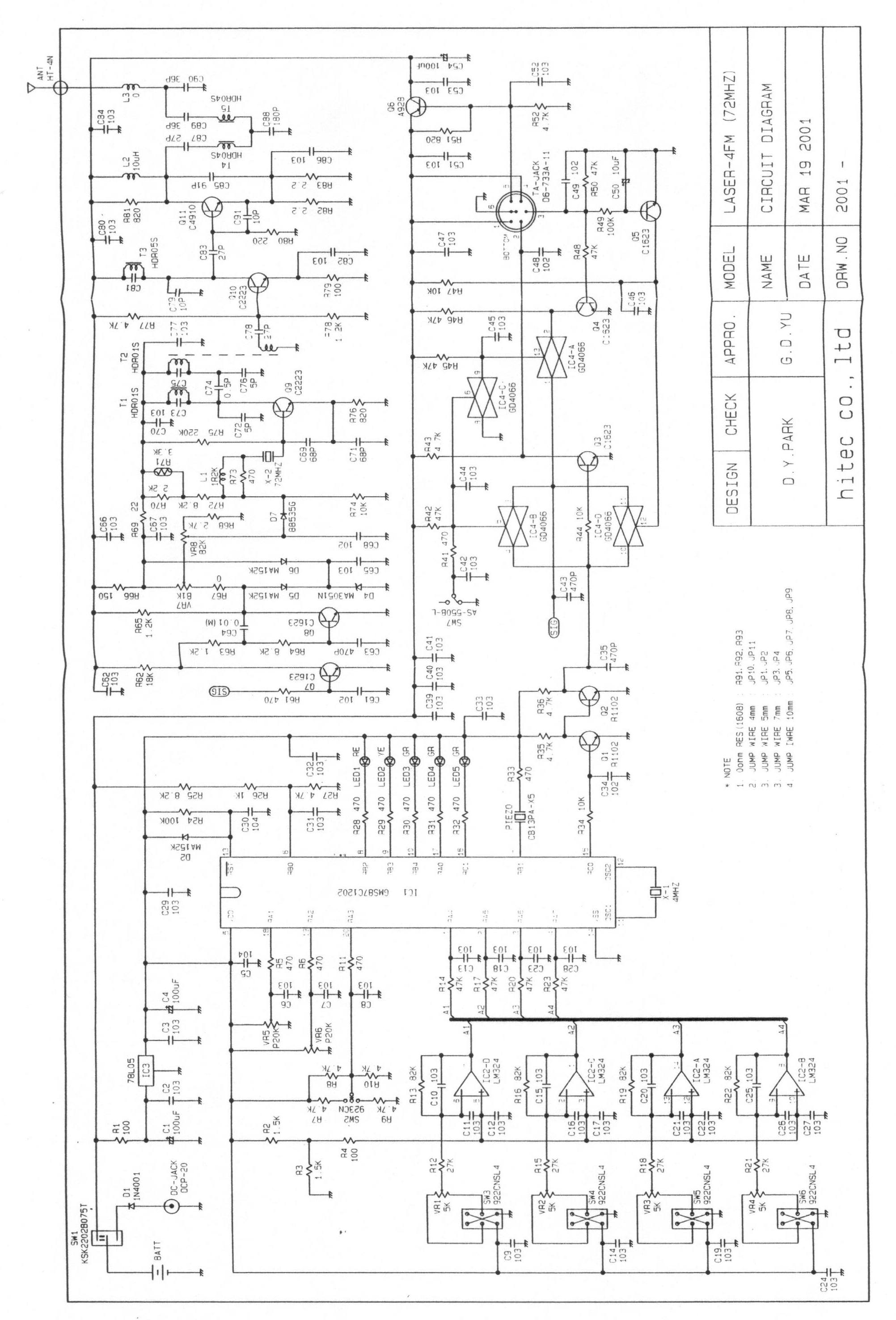
Tuning Procedures 1. Attach 12.0 Vdc power supply 2. Using a Spectrum analyzer and a short-range pick-up antenna, look for 72MHz signal with sufficient scan width to see 30-150 MHz spurious. 3. Adjust T1, T2, T3, T4, and T5 for maximum output at operating frequency and minimum output at any harmonics. 4. Repeat step 6. 5. Check for minimum emissions from 30 to 760 MHz.
Test Report
ENGINEERING STATEMENT For Type Certification of Hitec RCD, Inc. Model: Laser4/6 FCC ID: IFHLAS46 I am an Electronics Engineer, a principal the firm of Hyak Laboratories, Inc., Springfield, Virginia. My education and experience are a matter of record with the Federal Communications Commission. Hyak Laboratories, Inc. has been authorized by Hitec RCD, Inc., to make type certification measurements on the Laser4/6 transmitter. These tests were made by me or under my supervision in our Springfield laboratory. Test data and other documentation required by the FCC for type certification are included in this report. It is submitted that the above mentioned transmitter meets FCC requirements and type certification is requested. ______________________________ Rowland S. Johnson Dated: April 30, 2001 A. INTRODUCTION The following data are submitted in connection with this request for type certification of the Laser4/6 transmitter in accordance with Part 2, Subpart J of the FCC Rules. The Laser4/6 is a low power, non-voice, transmitter intended for remote control of model aircraft in the 72 MHz band. The equipment employs a vertical polarized antenna directly mounted on the unit and meets Paragraphs 95.645, 95.647, 95.649, and the technical requirements established in the Report & Order in PR Docket 90-222. B. GENERAL INFORMATION REQUIRED FOR TYPE CERTIFICATION (Paragraph 2.983 of the Rules) 1. Name of applicant: Hitec RCD, Inc. 2. Identification of equipment: IFHLAS46 a. The equipment identification label is submitted as a separate exhibit. b. Photographs of the equipment are submitted as separate exhibits. 3. Quantity production is planned. 4. Technical description: a. 6k00F1D emission b. Frequency range: 72.010 – 72.99 MHz. c. Operating power of transmitter is fixed at the factory at 0.43 Watt – ERP(d). d. Maximum power permitted under Paragraph 95.635(b) of the FCC Rules is 750 milliwatts, and the Laser4/6 fully complied with those power limi- tations. e. The dc voltage and dc currents at final amplifier: Collector voltage: 9.6 Vdc Collector current: 150 mA f. Function of each active semiconductor device: See Appendix 1. g. Complete schematic diagram is submitted as a separate exhibit. h. Draft instruction book is submitted as a separate exhibit. 2 B. GENERAL INFORMATION (continued) i. The transmitter tune-up procedure is submitted as a separate exhibit. j. A description of circuits for stabilizing frequency is included in Appendix 2. k. A description of circuits and devices employed for suppression of spurious radiation and for limiting modulation is included in Appendix 3. l. Not applicable. 5. Data for 2.985 through 2.997 follow this section. 6. RF_Power_Output (Paragraph 2.985(a) of the Rules) Since the Laser4/6 has an immediately attached, integral antenna, no antenna port exists. Power was determined by substitution comparison. Assuming an ideal dipole (not the actual monopole) ERP(d) = 0.43 Watts. C. MODULATION CHARACTERISTICS Occupied_Bandwidth (Paragraphs 2.989(i), and 95.635(b) of the Rules) Figure 1 is a plot, with unmodulated carrier at 0 dB Ref., of the sideband envelope of the transmitter taken with a Tektronix 494P spectrum analyzer. Modulation corresponded to conditions of 2.989(i) and consisted of the multiple pulses and synchronizing space normally used in radio control applications. Operator controls were adjusted for worst-case emission. The plot is within the limits imposed by paragraph 95.635(c). The horizontal scale (frequency) is 10 kHz per division and the vertical scale (Amplitude) is a logarithmic presentation equal to 10 dB per division. Resolution bandwidth was 1 kHz; video bandwidth was 100 kHz. Figure 2 is a plot from a Tektronix 494P spectrum analyzer with 2 mS/division sweep in the time domain of the modulated carrier. Modulation consisted of six bursts with a nominal 0.8 mS duration at a nominal 50 Hz repetition rate. 3 FIGURE 1 OCCUPIED BANDWIDTH 95.635: (3) At least 25 dB on any frequency removed from the center of the authorized bandwidth by more than 50% up to and including 100% of the authorized bandwidth (4 to 8 kHz). (10) At least 45 dB on any frequency removed from the center of the authorized bandwidth by more than 100% up to and including 125% of the authorized bandwidth. (8 to 10 kHz) (11) At least 55 dB on any frequency removed from the center of the authorized bandwidth by more than 125% up to and including 250% of the authorized bandwidth. (10 to 20 kHz) (12) At least 56+10 log 10 (TP) dB on any frequency removed from the center of the authorized bandwidth by more than 250%. OCCUPIED BANDWIDTH FCC ID: IFHLAS46 FIGURE 1 4 FIGURE 2 MODULATING WAVEFORM TIME DOMAIN 2 millisecond/division sweep OCCUPIED BANDWIDTH (Modulating Waveform) FCC ID: IFHLAS46 FIGURE 2 5 D. SPURIOUS EMISSIONS AT THE ANTENNA TERMINALS (Paragraph 2.991 of the Rules) Since the Laser4/6 transmitter meets FCC Rules 95.645, there are no provisions for antenna terminal output measurements. Substitution of a suitable matching network and retuning to permit observations at 50 ohms would not be representative of normal operation. Accordingly data on radiated spurious emissions are included in lieu of antenna terminal conducted spurious emissions. E. MEASUREMENTS OF SPURIOUS RADIATION (Paragraph 2.993(a) (b) (2) of the Rules) Measurements of radiated spurious emissions from the Laser4/6 were made with a Tektronix 494P spectrum analyzer using EMCO 3121C calibrated test antennas using substitution comparison. The transmitter and its integral vertical antenna were located in an open field 3 meters from the test antenna. Supply voltage was from a fresh set of batteries with a terminal voltage under load of 9.6 Vdc. The transmitter and test antennas were arranged to maximize pickup. Both vertical and horizontal test antenna polarization were employed. Reference was power at the carrier frequency. The measurement system was capable of detecting signals 100 dB or more below the reference level. M…
Text truncated - open the document above for the full version.
Contact Information
Applicant
Tony Ohm(Service Dept. Manager)
Test Firm
Hyak Laboratories, Inc.Rowland Johnson
703-451-1188
Technical Specifications
| # | Rule Parts | Frequency Range | Power Output | Emission | Tolerance |
|---|---|---|---|---|---|
| 1 | 95C | 72.01 MHz - 72.99 MHz | 430.00 mW | 6K00F1D | 0.0020000000 % |
Other Applications from Hitec RCD Inc.
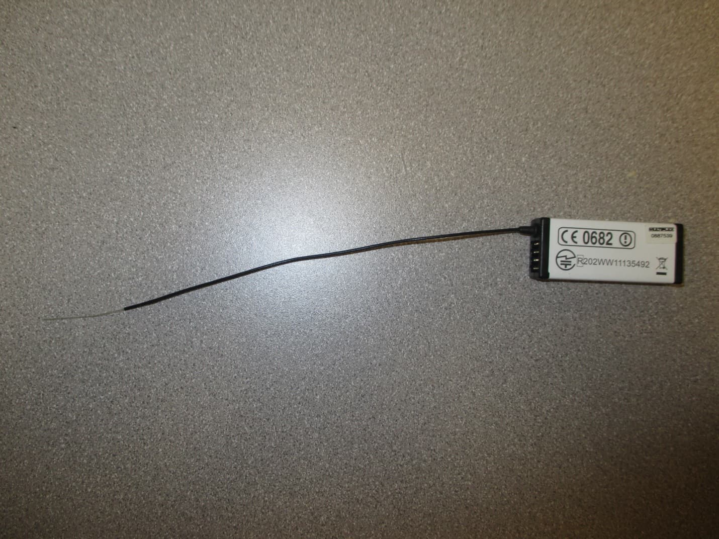
IFHRX57MLINK
Dec 22, 20147 CHANNEL 2.4 GHz TRANSCEIVER
Equipment Class
DSS - Part 15 Spread Spectrum Transmitter
IFHRX5MLINK
Dec 16, 2014RX5 M-LINK CHANNEL 2.4 GHz TRANSCEIVER
Equipment Class
DXX - Part 15 Low Power Communication Device Transmitter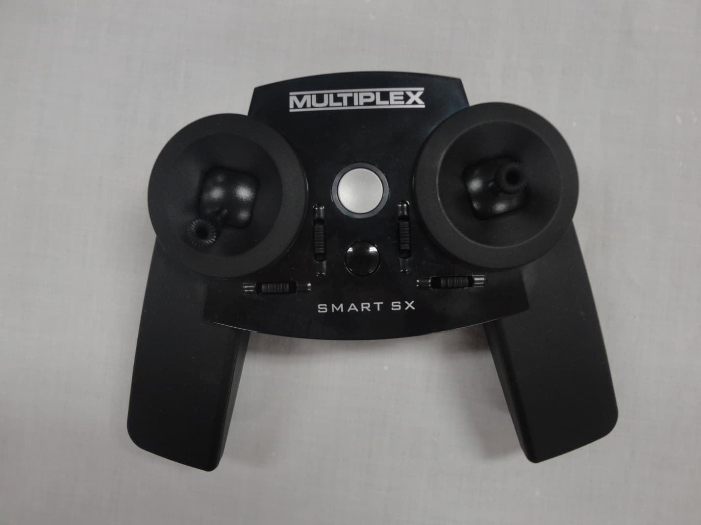
IFHSMART-SX
Sep 16, 20146 CHANNEL 2.4 GHz RADIO CONTROL TRANSMITTER
Equipment Class
DSS - Part 15 Spread Spectrum Transmitter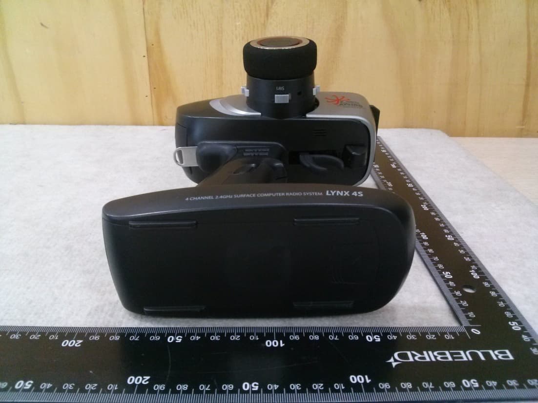
IFHLYNX4S
Jul 22, 20142.4GHz Radio Control System
Equipment Class
DSS - Part 15 Spread Spectrum Transmitter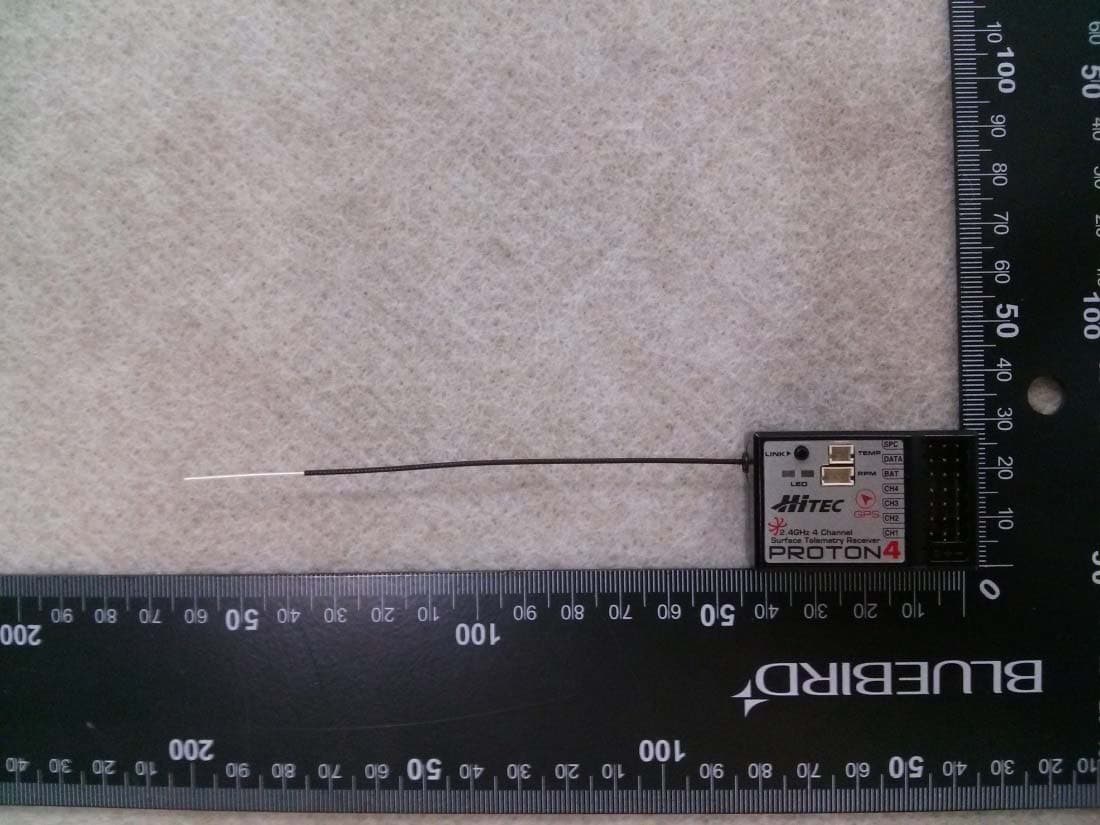
IFHPROTON4
Jul 22, 20142.4GHz Radio Control System
Equipment Class
DSS - Part 15 Spread Spectrum Transmitter