IFHLITE42.4GHz RADIO CONTROL SYSTEM
Hitec RCD Inc.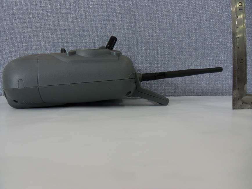
Click to zoom
Application Details
- Equipment Class
- DSS - Part 15 Spread Spectrum Transmitter
- Date of Grant
- Feb 27, 2012
- Application Purpose
- Original Equipment
- Date of Application
- Feb 27, 2012
- Equipment Note
- 2.4GHz RADIO CONTROL SYSTEM
- Frequency Range
- 2405.60000000 - 2477.60000000
- Company
- Hitec RCD Inc.
- Country
- United States
Documents & Files
Document Text
Text extracted from the exhibit documents filed with the FCC. Open a document above to read the original.
Users Manual
Instruction Manual 2 Thank you for purchasing the LITE4 2.4 digital proportional radio control system. LITE4 2.4 is easy to use and utilizes the latest in solid-state components for unsurpassed reliability and performance. It is important that you read and understand this manual before you attempt to operate your system. *NOTE : LITE4 2.4 is Compatible With all Minima Series Receivers. (Not Compatible With Optima Series Receivers) Introduction Introduction Table of Contents 1. Transmitter 2. Battery Installation 3. Operation 4. Set-up and Use of LITE4 2.4 5. Precautions 6. Mode Change 7. Service & Support Page 2. Page 3. Page 4. Page 5. Page 6. Page 7. Page 8. Page 10. Page 11. Page 12. Page 13. Page 14. Page 15. Table of Contents LITE4 2.4 Instruction Manual A. Features B. Layout C. Specifications D. Servo Reversing E. Control Stick Adjustment F. Stick Lever Tension Adjustment G. Trim Levers H. Reading the LED Battery Indicator A. Connection Diagrams B. Equipment Mounting C. Vibration and Water D. Antenna Installation (Minima 6S) E. Operating with a Trainer Cord A. ID-Set up A.K.A, Link or Bind B. SmartScan Function C. Range Check Function D. Min. and Max. Range for Binding E. Receiver-Servo Connection List F. Trim Adjustment G. ELVN (Elevon Mix) H. S. REV (Servo Reverse) I. V.TAIL (V-Tail) B. Layout 3 1. TRANSMITTER - Ergonomically designed 4 channel 2.4GHz(AFHSS) transmitter. - High quality precision gimbals with adjustable stick length and tension. - Servo reversing on all channels. - V-tail and Elevon Mixing - Trainer system. (Slave mode only) - Dry battery pack for 4cells for Alkaline battery - Easy to read 1 LED battery indicators. - SIC (Simulator Interface Cable) Compatible FRONT Handle LED indicator Aileron trim Power switch Elevator trim Aileron/ Elevator stick in MODE II Neck-strap connector Transmitter antenna Throttle/Rudder stick in MODE II Throttle trim Rudder trim LITE4 2.4 Instruction Manual The Link button can be used for the Link (ID setting) process between the LITE 4 2.4 radio and Hitec minima receiver, entering the power down mode for range check, activating SmartScan function. The LED indicator shows current working status of the radio with red lights. For more detailed information, please read pages 10 and 11. "LINK" button and LED Indicator The Mixing switch is used for mixing the function of servos with different wing types. ( V-TAIL and ELEVON ) "Mixing ( V-TAIL and ELEVON )" slide switch The REV switch is used for reversing the direction of the servos. "REV (Servo Reverse)” slide switch When the transmitter battery power descends to 4.4v or lower, Red color LED will be blinking. "Low Battery Warning” Link V-TAIL OFF ELEVON CH1CH2CH3CH4 REV NOR 2.4GHz 4 Channel Aircraft Radio LINK Button REV (Servo Reverse)”slide switch(Mixing V-TAIL and ELEVON)”slide switch Link V-TAIL OFF ELEVON CH1CH2CH3CH4 REV NOR 2.4GHz 4 Channel Aircraft Radio A. Features - Power supply : 6V 4cell Dry battery - Current drain : 100mA - Output power : 100mw - Modulation : 2.4G AFHSS Single Directional - LITE4 2.4 transmitter is equipped with servo reversing on all channels. - If you need to change travel direction of rotation, open the battery case and move the servo reversing switch. - The unique open-stick assembly provides fully adjustable stick tension to adjust the feel of the sticks in your hands. - You may adjust the stick tension of your sticks to provide the feel that you like for flying. To adjust your springs, you'll have to remove the rear case of the transmitter. Using a screwdriver, remove the six screws that hold the transmitter's rear cover into position, and put them in a safe place. Gently ease off the transmitter's rear cover and move it to the under side of the transmitter, carefully turning it as you would turn the page of a book. Now you'll see the view shown in the illustration. Using a small Philips screwdriver, rotate the adjusting screw for each stick for the desired spring tension. The tension increases when the adjusting screw is turned clockwise, and decreases for counterclockwise motion. When you are satisfied with the spring tensions, you may close the transmitter. Very carefully reinstall the rear cover. When the cover is properly in place, tighten the six screws. - The length of the non-slip control sticks can be adjusted to suit the requirements of the user. AB LITE4 2.4 Lever Tension Tension adjusting screw 4 LITE4 2.4 Instruction Manual C. Specifications D. Servo Reversing E. Control Stick Adjustment F. Stick Lever Tension Adjustment - The trim levers associated with each control stick are used to correct or (trim-out) the tracking of the aircraft. - (Caution) Make sure the trims will move the surface past neutral when moved to their extremes. This will assure you have adequate trim control. - After your plane's first test flight, note the positions of the control surfaces that required trim. Next, center the trims and turn the receiver off. Now adjust the control linkage on the plane so the surfaces are in the same position before the trim levers were re-centered. - Turn on the radio and receiver and recheck the control surfaces to ensure that all the corrections were applied in the proper direction. -There is one indicator lights on the face of the radio marked High and Low (blinking). -These relate to the condition of your transmitter battery and the other setups. Please pay attention to these LED lights and stop flying when the LED light is blinking. 2. BATTERY INSTALLATION - The transmitter requires four and the receiver battery pack needs four AA size batteries. These can be Alkaline cells - When loading the batteries, make sure the receiver and transmitter switches are in the "off" position. - Open the battery door in the back of the transmitter by pressing the tab on the bottom of the battery door and lifting up. - Load batteries into the appropriate slots, taking care to install according to the proper polarity. - Replace the battery door and tu…
Text truncated - open the document above for the full version.
External Photos
Photo 1: Exterior Photographs Top Bottom Side 1 Side 2 Side 3 Side 4
ID Label/Location Info
1177 Lite4 FCC ID: IFHLITE4 IC: 3420A-LITE4 KCC-CRI-HRK-LITE4 당해 무선설비는 운용 중 전파혼신가능성이 있음 005UVAA0006 R
Internal Photos
Interior view of EUT Internal Photos View of Main PCB(Top) View of Main PCB(Bottom) View of Module (Top) View of Module (Bottom)
Operational Description
Specification For Approval Type Dipole - ANT Model Name SB – 24D – ANT Part No Issued Date 2011. 06. 22 SAE HAN ANTENNA CO.,LTD 301-1107,Ssangyong Techno Park 3,36-1 Samjeong-Dong, Ojeong-Gu, Bucheon-Si, Gyeonggi-Do, Korea TEL : 82.32.624.2630 FAX : 82.32.624.2632 Charge Inspector Approval CONTENTS 1. Revision History ............................................ ..3 2. Specification ............................................. 4 3. Electrical Specification Test 3.1 V.S.W.R .............................................5 3.2 Beam Pattern .............................................7 4. Appearance ..............................................9 Model Name Part No Rev Page SAE HAN ANTENNA CO.,Ltd SB – 24D 0.0 2 / 8 1. Revision History Rev No Date Contents Charge Remarks 0.0 2011. 06. 22 New Established Hwang Dong Min Model Name Part No Rev Page SAE HAN ANTENNA CO.,Ltd SB – 24D 0.0 3 / 8 2. Specification 2.1. Electrical Specification Item Spec Remarks Center Frequency 2441MHz Frequency Range 2400MHz – 2500MHz V.S.W.R Less Than 2.0 Gain(dBi) 2.1dBi (Max) Radiation pattern Omni-directional Polarization Linear Impedance 50Ω Normal ± 10 2.2. Mechanical Specification Item Spec Remarks Dimensions(LxWxH) 136 x 1.13 mm Connector Soldering Color Black Operating Temperature -45°C ~ +85°C Weight 8g ± 0.2g 2.3. Major Materials Of Parts Item Materials Remarks Sleeve Keyflex Ground Plane C3604 Jonit Nylon Coaxial Cable Jacket,Teflon,swc,cu Model Name Part No Rev Page SAE HAN ANTENNA CO.,Ltd SB – 24D 0.0 4 / 8 3. V.S.W.R Test 3.1. Test method ① Network Analyzer Spec Equipment Model Specification Network Analyzer HP8753ES · Freq. Range : 300KHz ~ 6GHz Calibration Kit HP85032B · DC ~ 6GHz (SMA-Type) ② Network Analyzer test method Model Name Part No Rev Page SAE HAN ANTENNA CO.,Ltd SB – 24D 0.0 5 / 8 3. Electrical Specification 3.2 V.S.W.R DATA Frequency VSWR Remarks 2400MHz 1.21 2441MHz 1.06 2483MHz 1.20 Model Name Part No Rev Page SAE HAN ANTENNA CO.,Ltd SB – 24D 0.0 5 / 8 2.2 Gain & Beam Pattern Test ① Chamber Spec Section Specification Chamber Size 6(L)m X 3(W)m X 3(H)m Frequency Range 400MHz – 6GHz (Far Field) Quiet Zon 1m X 1 m @ 1GHz Type Rectangular Antenna weight < 50 kg ② Chanmber Test method Model Name Part No Rev Page SAE HAN ANTENNA CO.,Ltd SB – 24D 0.0 5 / 8 Positioner Control Microwave Receiver Printe r Roll Positioner GPIB RF Cables S ystem Cable Far Field Measurement Software System Controller Az/El/Az Positioner Antenna Under Test Standard Gain Horn Antenna 3.2. Gain & Beam Pattern Frequency Gain(dBi) 2400MHz 1.53 2441MHz 1.62 2483MHz 1.85 Model Name Part No Rev Page SAE HAN ANTENNA CO.,Ltd SB – 24D 0.0 6 / 8 4. Drawing Model Name Part No Rev Page SAE HAN ANTENNA CO.,Ltd SB – 24D 0.0 7 / 8
Test Report
Report Number :KSQ-FCC120203FCC ID : IFHLITE4, IC : 3420A-LITE4 Page 2/38 TABLE OF CONTENTS 1. GENERAL.................................................................................................................................................5 2. TEST SITE.................................................................................................................................................5 2.1 Location................................................................................................................................................5 2.2 Test Date...............................................................................................................................................5 2.3 Test Environment..................................................................................................................................5 3. DESCRIPTION OF THE EQUIPMENT UNDER TEST..........................................................................6 3.1 Rating and Physical Characteristics.......................................................................................................6 3.2 Equipment Modifications......................................................................................................................6 3.3 Submitted Documents...........................................................................................................................6 4. MEASUREMENT CONDITIONS............................................................................................................7 4.1 Description of test configuration...........................................................................................................7 4.2 List of Peripherals.................................................................................................................................7 4.3 Type of Used Cables..............................................................................................................................7 5. TEST AND MEASUREMENT.................................................................................................................8 5.1 ANTENNA REQUIREMENT..............................................................................................................8 5.1.1 Regulation.......................................................................................................................................8 5.1.2 Result..............................................................................................................................................8 5.2. 20dB BANDWIDTH...........................................................................................................................9 5.2.1 Regulation.......................................................................................................................................9 5.2.2 Test Condition................................................................................................................................9 5.2.3 Test result........................................................................................................................................9 Table 1 : Measured values of the 20dB Bandwidth..........................................................................................9 Figure 1 Plot of the 20dB Channel Bandwidth.............................................................................................10 5.3. MAXIMUMPEAKPOWER.............................................................................................................12 5.3.1 Regulation.....................................................................................................................................12 5.3.2 Test Condition...............................................................................................................................12 5.3.3 Test result......................................................................................................................................12 Table 2 : Measured values of the Maximum Peak Output Power(Conducted)......................................................12 Figure 2 : Plot of the Maximum Peak Output Power(Conducted).....................................................................13 5.4. POWERSPECTRALDENSITY.......................................................................................................15 5.4.1 Regulation.....................................................................................................................................15 5.4.2 Test Condition...............................................................................................................................15 Report Number :KSQ-FCC120203FCC ID : IFHLITE4, IC : 3420A-LITE4 Page 3/38 5.4.3 Test result......................................................................................................................................15 Table 3 : Measured values of the Power Spectral Density...............................................................................15 Figure 3 : Plot of the Power Spectral Density...............................................................................................16 5.5. CARRIER FREQUENCY SEPARATION........................................................................................18 5.5.1 Regulation.....................................................................................................................................18 5.5.2 Test Condition...............................................................................................................................18 5.5.3. Test result.....................................................................................................................................18 Table 4 : Measured values of the Carrier Frequency Separation.......................................................................18 Figure 4 : Plot o…
Text truncated - open the document above for the full version.
Contact Information
Applicant
Tony Ohm(Service Dept. Manager)
Test Firm
Korea Standard Quality LaboratoriesJae-Ju Lee
Technical Specifications
| # | Rule Parts | Frequency Range | Power Output |
|---|---|---|---|
| 1 | 15C | 2.41 GHz - 2.48 GHz | 65.00 mW |
Other Applications from Hitec RCD Inc.
IFHRX57MLINK
Dec 22, 20147 CHANNEL 2.4 GHz TRANSCEIVER
Equipment Class
DSS - Part 15 Spread Spectrum Transmitter
IFHRX5MLINK
Dec 16, 2014RX5 M-LINK CHANNEL 2.4 GHz TRANSCEIVER
Equipment Class
DXX - Part 15 Low Power Communication Device Transmitter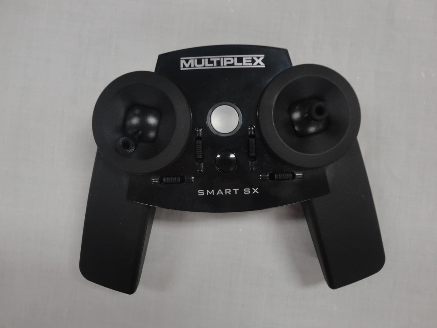
IFHSMART-SX
Sep 16, 20146 CHANNEL 2.4 GHz RADIO CONTROL TRANSMITTER
Equipment Class
DSS - Part 15 Spread Spectrum Transmitter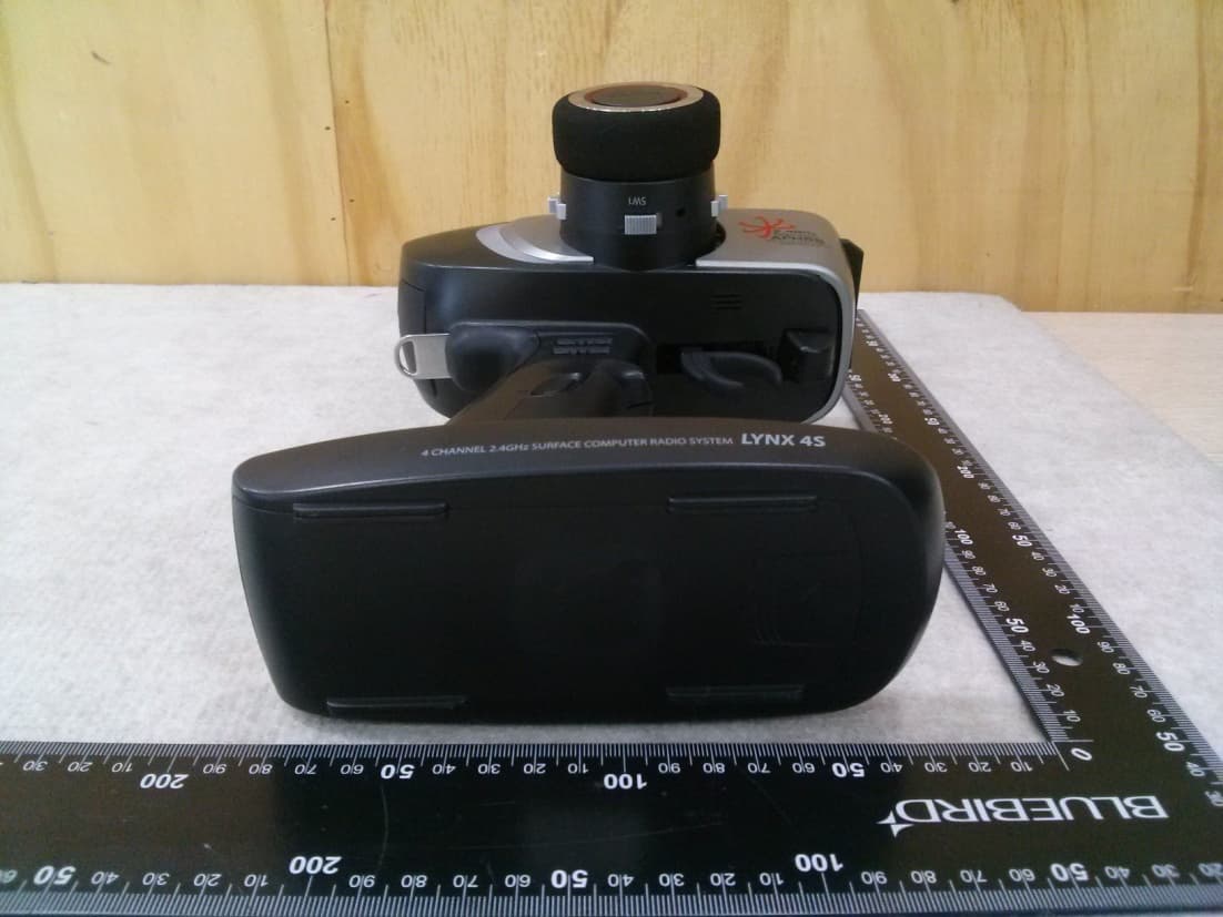
IFHLYNX4S
Jul 22, 20142.4GHz Radio Control System
Equipment Class
DSS - Part 15 Spread Spectrum Transmitter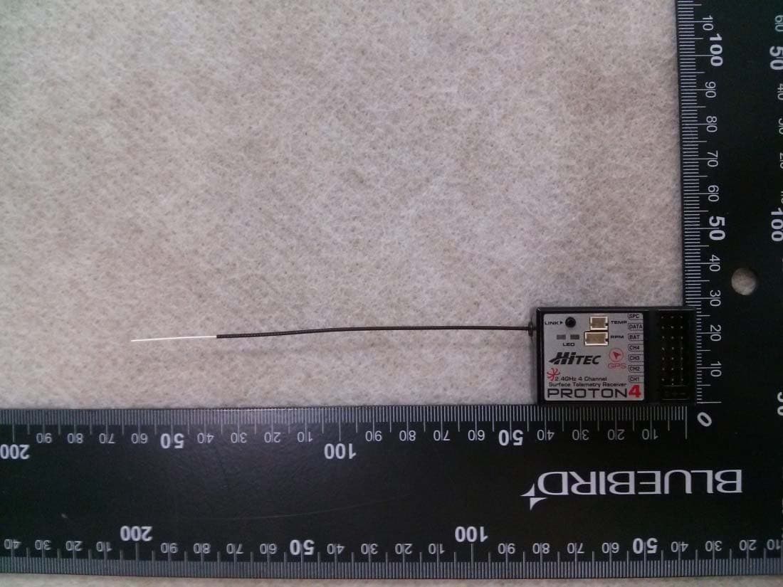
IFHPROTON4
Jul 22, 20142.4GHz Radio Control System
Equipment Class
DSS - Part 15 Spread Spectrum Transmitter